IDX WR88 User manual

Wicket Reader Interfaces
For Carwash, Laundry, Arcade And Other Markets
Rev. 10/2008
General Description
The WR88 Wicket Reader requires 5VDC to operate and has both an
output signal and an input signal for connecting it to the system
equipment. The WR88 may be configured in the field to use those input
and output signals for serial data communication, or it may use them to
create an output pulse and to monitor the operational status of the system
equipment. These Wicket Reader Interface Modules have been designed to
convert local available power to 5VDC and provide the proper interface
voltages, currents, and connectors for interfacing to a variety of system
equipment.
Interface modules covered in this document include:
WK-LV Module: Pulse Output - Low Voltage Interface
WK-HV Module: Pulse Output - High Voltage Interface
WK-CD Module: Serial Port – Card-Display Protocol
WK-MDB Module: Serial Port - MDB Vendor Protocol
Interface documentation for Turbo Accessories applications, including Wickets Jackpot, Registration &
Redemption, and Night Access Door Control, are found within the Turbo Accessories documentation.
Pulse Output - Low Voltage: WK-LV Module
The Model WK-LV Pulse Output - Low Voltage
Interface Module was primarily designed for
applications powered by either 24VAC or 12-
28VDC and requiring a "coin pulse" style interface
to activate the service equipment. Such
applications include carwash equipment, laundry
equipment, low voltage arcade games and other
similar equipment.
Its three diagnostic LED indicators provide visual operational information that may be helpful during
installation and for troubleshooting problems. The enclosure dimensions are 3.3" L x 2.2" W x 1.0" H
(84mm x 56mm x 20mm) and comes with adhesive Velcro mounting strips. An RJ-11 telephone style
connector on the right side of the enclosure is to plug in the WR88 Wicket Reader. A wiring harness with
16" leads plugs into the field wiring connector on the left hand side of the enclosure. Note: Because there
is more than one style of wiring harness (see below) it is a separately ordered item.
The reed relay output provides both N.O. (normally open) and N.C. (normally closed) dry contacts in
order to interface as universally as possible. Typically the Relay N.O. and Relay Common terminals will
be connected in parallel to those of other "coin pulse" generating devices. The Relay Common contact has
an automatically resettable fuse to protect the module from wiring errors and other problems. The Service
Monitor input is used to sense if power to the equipment has been applied. The Wicket Reader monitors
this signal to determine the following; a) whether to charge the Start Up Amount or the Increment
Amount, or b) whether to indicate that the equipment is running (Wicket Reader face turns white).
Wickets Administrator is used to configure the WR88 Wicket Reader's use of this signal, including
enable/disable and whether Service Sense logically corresponds to a high or low voltage sensed at the
input.
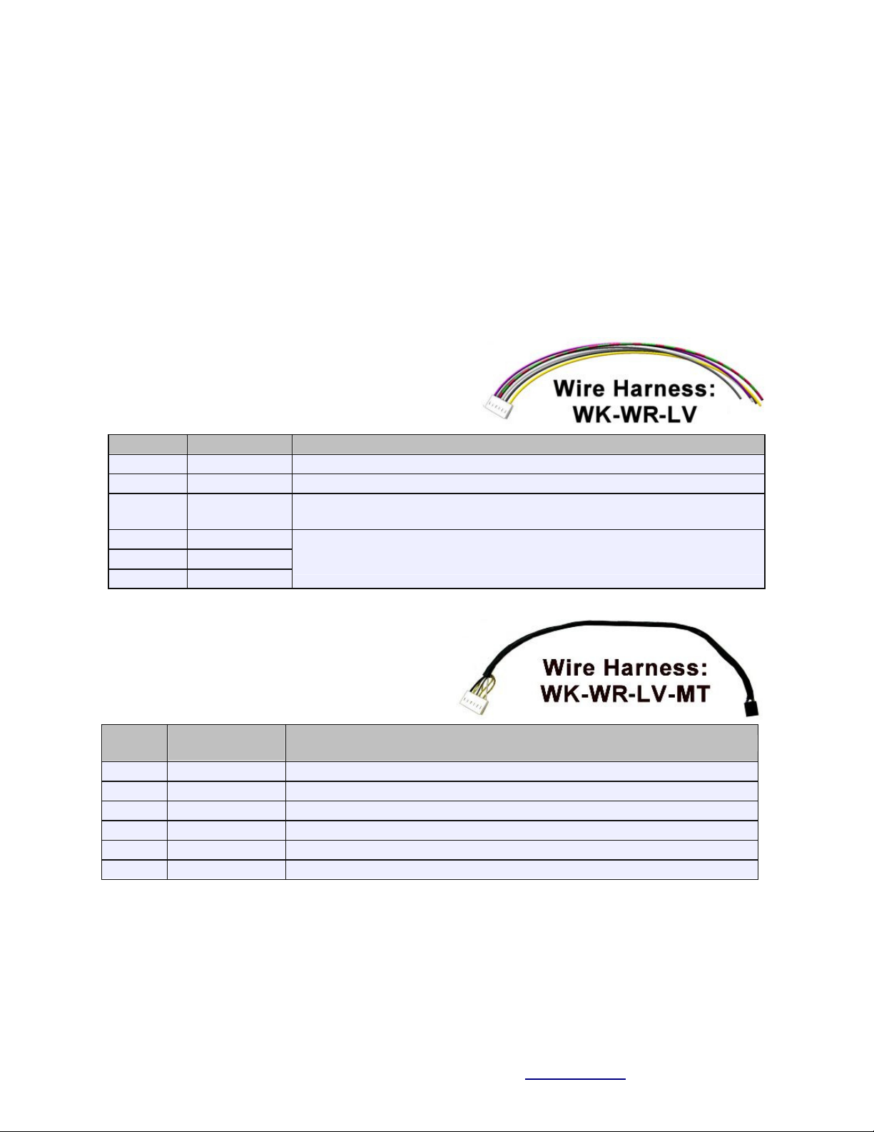
One of the below wiring harnesses must be ordered with the WK-LV Module for field wiring:
The WK-WR-LV wire harness has 16" leads and is intended
for general purpose retrofit interface. IDX can assist you with
specific information on connecting to a variety of equipment.
Wire
Name
Description / Specification
1- Yellow
Power Hot
Power supply: 12-28VAC or 12-35VDC
2- Black
Power Common
Power Common - Ground
3- White
Service Monitor
Input threshold: 1.4VDC, 2K Ohms internal pull down. 28VAC/DC
maximum.
4- Red/Grn
Switch N.O.
5- Grey
Switch N.C.
6- Violet
Switch Com.
SPDT reed relay switch contacts:
0.30Amps @ 60VDC maximum. - with automatic resettable fuse.
The WK-WR-LV-MT wire harness is 16" in length and
is terminated with a connector for the Maytag Gen 1
Debit Specification for laundry equipment.
Wire
IDX Name
Maytag Name - Function Description / Specification
1
ServiceMonitor
Avail2 - Optocoupler emitter output for machine available signal.
2
--
Avail1 - Optocoupler collector for machine available signal: = PWR+
3
--
Enable1 - Optocoupler LED anode for debit pulse enable: = PWR+
4
Relay N.C.
Enable2 - Optocoupler LED cathode for debit pulse enable signal.
5
Power Hot
PWR+ - 26VDC @ 100mA max. for debit reader.
6
Power Common
PWR- - Power common for debit reader.
Note: Wickets Administrator must be used to program the WR88 Wicket Reader to enable it to generate
the correct pulses and debit a Customer Wicket by the proper amount. See below for information about
setting the configuration parameters for the WR88. A separate PDF document for Maytag-specific setup
instructions is available on the Web.
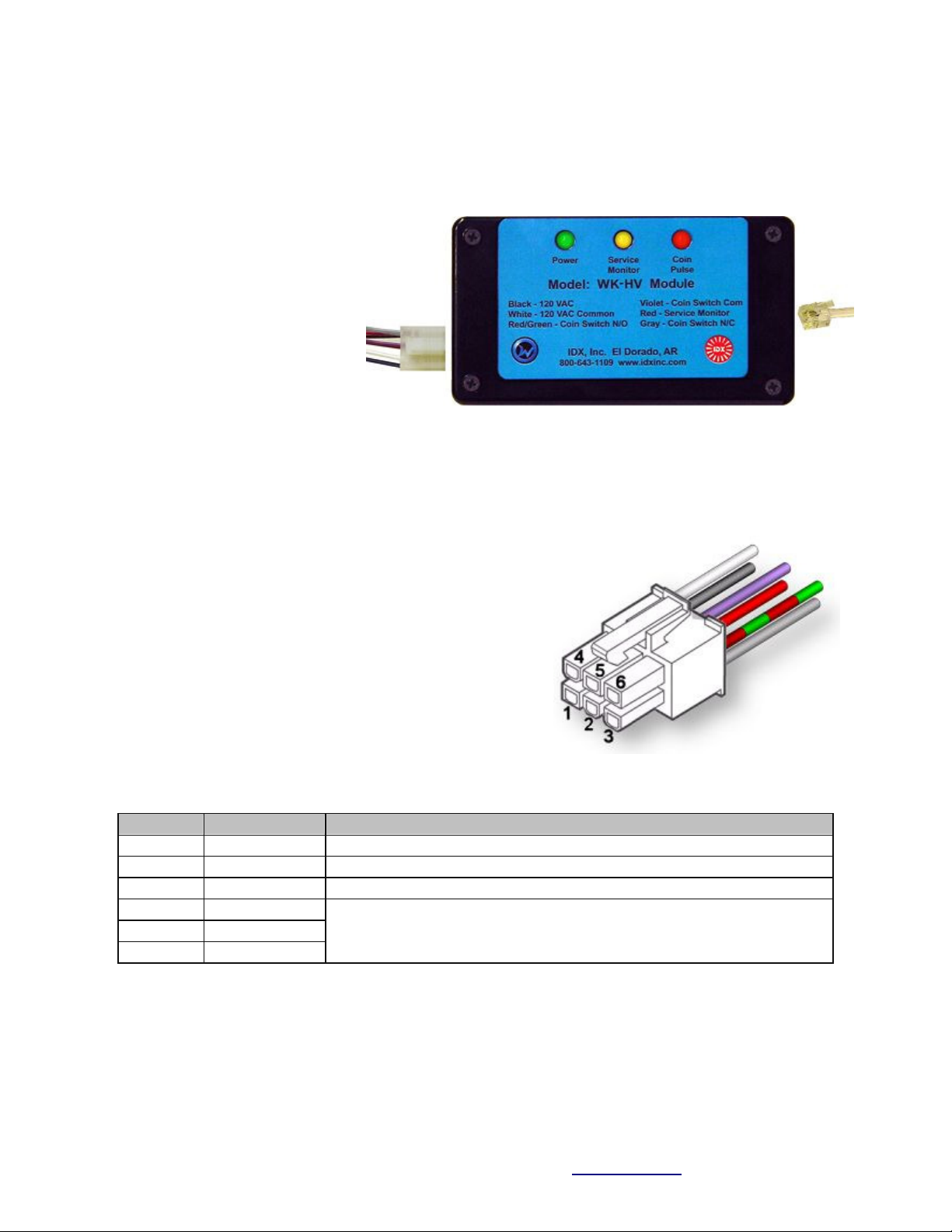
Pulse Output - High Voltage: WK-HV Module
The WK-HV Pulse Output - High Voltage Interface Module was primarily designed for applications
powered by 120VAC or 240VAC and requiring a "coin pulse" style interface to activate the service
equipment. Such applications
include laundry equipment, air
vendors, carwash vacuums, and
other similar equipment. Its three
diagnostic LED indicators provide
visual operational information that
may be helpful during installation
and for troubleshooting problems.
The enclosure dimensions are 4.4" L
x 2.4" W x 1.2" H (112mm x 61mm
x 30.5mm) and comes with adhesive
Velcro mounting strips.
The relay output provides both N.O. (normally open) and N.C. (normally closed) dry contacts in order to
interface as universally as possible. Typically the Relay N.O. and Relay Common terminals will be
connected in parallel to those of other "coin pulse" generating devices. The Service Monitor input is used
to sense if power to the equipment has been applied. The
Wicket Reader monitors this signal to determine the following;
a) whether to charge the Start Up Amount or the Increment
Amount, or b) whether to indicate that the equipment is running
(Wicket Reader face turns white). Wickets Administrator is
used to configure the WR88 Wicket Reader's use of this signal,
including enable/disable and whether Service Sense logically
corresponds to a high or low voltage sensed at the input.
There is an RJ-11 telephone style connector on the right side of
the enclosure to plug in the WR88 Wicket Reader. A pre-wired
connector with 16" leads plugs into the field wiring connector
on the left hand side of the enclosure and is included as part of the WK-HV Module. The table below
identifies the color and function of each of these wires.
Wire
Name
Description - Specification
1- Black
Power Hot
Power supply: 95-270VAC
2- Red
Service Monitor
Input threshold: 10VDC, 250VAC maximum.
4- White
Power Common
Power Common
3- Grey
Switch N.C.
5- Violet
Switch Common
6- Red/Grn
Switch N.O.
SPDT relay switch contacts:
8.0Amps @ 250VAC maximum. - not internally fused
Note: Wickets Administrator must be used to program the WR88 Wicket Reader to enable it to generate
the correct pulses and debit a Customer Wicket by the proper amount. See below for information about
setting the configuration parameters for the WR88.

Serial Port - MDB Vendor Protocol: WK-MDB Module
The MDB (multi-drop bus) serial port protocol
evolved to become the standard protocol between
the control components in vending machines in the
mid 1990's. The protocol specifies how the vending
machine controller talks to the coin changer, the
bill validator, the display, and installed card
readers.
The WK-MDB Module is designed to provide the
electrical and protocol interface between a vending
machine controller (VMC) and a WR88 Wicket Reader. Its three diagnostic LED indicators provide
visual operational information that may be helpful during installation and for troubleshooting problems.
The enclosure dimensions are 3.0" L x 2.5" W x 1.0" H (76mm x 63mm x 25mm) and has integral
mounting ears.
There is an RJ-11 telephone style connector on the right side of the enclosure to plug in the WR88 Wicket
Reader. There is an attached 16" cable assembly on the left hand side of the enclosure with two
connectors: one to connect to the vending machine controller, and the other which is just a daisy-chain
pass-through connector for connecting other devices to the multi-drop bus.
The MDB Spec V3.0 supports two cashless devices. The address select switch located on the left side of
the enclosure configures the WK-MDB Module as one device or the other. The valid cashless addresses
are 0x10 (address 1) and 0x60 (address 2). This provides a means for compatibility in a system already
having a credit card device installed. Any change made to the address select switch will not take effect
until the next module reset through a power cycle or if the vending machine controller commands a bus
reset.
Note: Wickets Administrator must be used to program the WR88 Wicket Reader to enable the MDB
Vendor Protocol to properly communicate with the WK-MDB-Module. See below for information about
setting the configuration parameters for the WR88.
A typical vending transaction for a customer would proceed something like this:
1.) A customer walks up to the vending machine to buy something using his Wicket.
2.) As in other transactions where money is first deposited, the Wicket is first read to start the sequence.
3.) The machine controller determines if the customer has enough to buy the lowest price item.
4.) The customer is prompted to make an item selection for vending.
5.) The customer is prompted to read his Wicket again to debit it and complete the transaction.
6.) The machine controller tells the Wicket Reader how much to debit the next presented Wicket.
7.) The Wicket Reader blinks white to indicate a Wicket debit transaction is pending for the amount.
8.) The customer reads his Wicket again, the amount is debited and the reader blinks green.

9.) The completed debit transaction is communicated back to the vending machine controller.
10.) The vending machine controller vends the item to the customer.
11.) If the item fails to vend, the vending machine controller sends a refund to the Wicket Reader.
12.) The Wicket Reader blinks white to indicate a pending refund transaction for the amount.
13.) The customer reads his Wicket again, the amount is refunded, and the Wicket Reader blinks green.
14.) If the same Wicket is not presented to take the refund within 30 seconds, the Wicket Reader goes
back to the idle blue color and saves the refund information for some future time when the Wicket is
again presented and completes the transaction then.
Note: The MDB Specification does not guarantee that you can just plug the WK-MDB Module and a
WR88 Wicket Reader into just any vending machine and expect it to work. The vending machine
controller may not be capable of communicating with a second cashless payment device, or it may have
an incompatible implementation of the communication sequence details. Please contact IDX sales for
compatibility information.
Serial Port - ard-Display Protocol: WK- D Module
The Card-Display Protocol was developed by IDX at
the request of various card acceptor manufacturers
to provide interoperability of credit and debit card
systems with the installed display-timers in self-service
carwash bays. Payment, display message, and status
information are communicated between the units via
RS-232.
The WK-CD Module is designed to provide the
electrical and protocol interface between a WR88
Wicket Reader and an Card-Display compatible
display-timer, such as the IDX BigTime, Little Two
Timer, or GigaTime. Its three diagnostic LED
indicators provide visual operational information that may be helpful during installation and for
troubleshooting problems. The enclosure dimensions are 3.3" L x 2.2" W x 1.0" H (84mm x 56mm x
20mm) and comes with adhesive Velcro mounting strips.
There is an RJ-11 telephone style connector on the right side of the enclosure to plug in the WR88 Wicket
Reader. There is also an attached 16" RJ-11 telephone style cable assembly on the left hand side of the
enclosure to plug directly into the Card-Display Protocol compatible display-timer.
Note: Wickets Administrator must be used to program the WR88 Wicket Reader to enable the Card-
Display Protocol so it will properly communicate through the WK-CD Module to the display timer. See
below for information about setting the configuration parameters for the WR88.
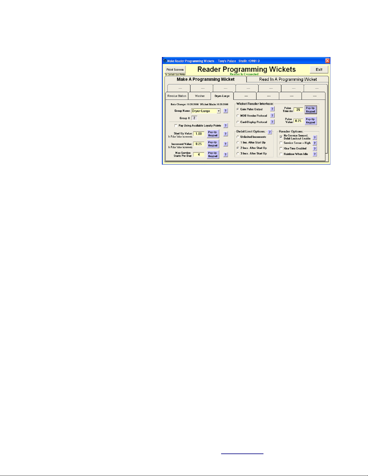
Wicket Reader onfiguration Steps
The Wickets Administrator software is
used to configure the WR88 Wicket
Reader so that it knows how to
communicate with the equipment and
what to do with customer Wickets when
presented. The screen shot to the right
shows an example of the setup parameters
you will need to program into your Wicket
Reader. Below are the setup steps:
1.) Click the Make A Programming
Wicket tab, then click a Group Tab for a
group of equipment that will all operate
with the same prices and parameters.
2.) Set the Group Name by clicking the drop-down box arrow and selecting a name from the list, which
include names for carwash, laundry, arcade, and vending applications, or you may directly enter any
name you like in the box. This name will then be shown on the tab.
3.) Set the Wicket Reader Interface according to the hardware interface the machine requires. Select the
Coin Pulse Output if the equipment requires coin pulses to activate it and you are using the WK-LV or the
WK-HV Module to interface to the machine. Select the MDB Vendor Protocol if the equipment is a
vending machine or a revalue station and you are using the WK-MDB Module to interface to the
machine. Select the Card-Display Protocol if the equipment is an IDX display-timer with that has the
Card-Display option and you are using the WK-CD Module to interface to it.
4.) If you have selected the MDB Vendor Protocol in the last step you will see most of the other controls
on the screen become unavailable as they are irrelevant to vending machine or revalue station
applications. Skip directly to step 10 to write this data to your Reader Programming Wicket.
5.) Set your operating prices (so the Wicket Reader will know how much to debit from a Customer
Wicket) by setting the Start Up Value and the Increment Value using the Pup-Up Keypad. The Start Up
Value is the minimum amount to debit to get the machine started and the Increment Amount is usually
some smaller amount to debit for additional time or services once the start amount has been satisfied. If
the Wicket Reader finds that the presented Wicket does not have sufficient funds to start a machine, it
won’t debit any funds at all from it and will blink yellow to warn of insufficient funds.
6.) Set the Debit Limit Options according to the number of incremental debits the machine can handle.
7.) Set the Pulse Time (in milliseconds) according to what your equipment expects to receive from coin
operated equipment as a valid coin pulse. Generally this value will be between 15ms and 100ms. If you
cannot find this information about your equipment, IDX recommends 50ms be used in the carwash
market and 25ms be used in the laundry, arcade, and other markets as your default choice.
8.) Set the Pulse Value. In most North American sites, coin pulses are based on a $.25 coin. However you
can set the coin pulse value to be pretty much anything you like. For example, in Europe and Australia
there are no 0.25 coins, so 0.20, or 0.50 or 1.00 may be what is required.

9.) In the Reader Options section:
a. Check the No Service - Debit Lockout Enable box to lockout further debits to customer Wickets
if there is no Service Sense signal (machine did not start) for 10 minutes following a debit from
the Wicket. When a lockout occurs, the Wicket Reader will continuously blink red to indicate the
problem. The debit lockout condition can be cleared by starting the machine or cycling power.
During debit lockout a customer can get his money refunded to his Wicket simply by reading his
Wicket on the same Wicket Reader one more time. The Wicket Reader will blink green to
indicate that the money has been refunded to the Wicket.
b. Check the Service Sense = High box if the voltage sensed by the Service Sense Input to the
Wicket Reader goes high when the machine is activated. This is case with most equipment.
However, in cases the opposite is true, such as in Maytag laundry machines that produce a
“machine available” signal which does the logical opposite and thus requires you to leave the box
unchecked.
c. Check the Xtra-Time Enabled box only if the Wicket Reader is tied into an IDX carwash timer
with Xtra-Time enabled (or a competitor’s timer with a Grace Time feature enabled). This will
cause the Wicket Reader to debit only the Increment Value for the first 20 seconds after the
Service Sense input indicates the machine has turned off... and then only after that 20 seconds
expires (without the machine being turned back on) will the Wicket Reader thereafter debit the
full Start Up Value from a customer’s Wicket to initiate a new service cycle. Leave this box
unchecked if your equipment does not have an Xtra-Time or Grace Time feature.
d. Check the Rainbow When Idle box you would like the Wicket Reader face to occasionally
depart from its normal blue idle color and quickly cycle through the colors of the rainbow. This
feature can help attract attention to the Wicket Reader, but some may be concerned that it may
confuse the customer if it occurs about the time the customer is reading his Wicket. Your choice.
10.) When you are done, tap your Reader Programming Wicket on the Wicket Reader Programming
Module to have it write this configuration information to the Wicket.
11.) Take the Reader Programming Wicket around to all of the machines that will operate with these
particular configuration parameters and tap the Wicket on the machine’s Wicket Reader to have it read in
and program itself with these parameters. The Wicket Reader will blink green to indicate that it has
successfully read the parameters from the Reader Programming Wicket.
Table of contents
Other IDX Power Supply manuals


