IEF Werner profiLINE 140 User manual

March 2019 Translation of the original instructions
MAN_EN_1039740_profiLINE140_R3d.docx profiLINE 140 Page 1 of 48
IEF-Werner GmbH
Wendelhofstraße 6
78120 Furtwangen - Germany
Phone: + 49 7723-925-0
Fax: + 49 7723-925-100
www.IEF-Werner.de
info@IEF-Werner.de
Translation of the original instructions
profiLINE 140
Edition: March 2019
Article no.: 1039740

Translation of the original instructions March 2019
Page 2 of 48 profiLINE 140 MAN_EN_1039740_profiLINE140_R3d.docx
Change History
Trademarks and trade names are used without any warranty of their free usability. Texts and
examples were created with great care. Nevertheless, errors cannot be excluded. IEF-Werner GmbH
does not assume legal responsibility nor any liability for missing or incorrect statements and their
consequences.
IEF-Werner GmbH reserves the right to modify or improve the software or hardware or parts of it, as
well as the supplied documentation or parts of it, without previous notice.
IEF-Werner GmbH expressly reserves all rights for replication and photomechanical reproduction,
including in extracts.
We are always grateful for suggestions for improvements and information about errors.
© March 2019, IEF-Werner GmbH
Document Code Date Revision
EN_profiLINE140_R3b.doc July 2005 Release of the English document.
MAN_EN_1039740_pofiLINE140_R3c.doc April 2013 Formal changes. Translation from German Document:
“MAN_DE_1039739_profiLINE140_R4d.doc”.
MAN_EN_1039740_pofiLINE140_R3d.docx 05.03.2019 Updating the document in relation to new EMC and low
voltage directive

March 2019 Translation of the original instructions
MAN_EN_1039740_profiLINE140_R3d.docx profiLINE 140 Page 3 of 48
Table of Contents
1Safety ...............................................................................................................................................5
1.1 Definition or warning notes .....................................................................................................5
1.2 General warning notes ...........................................................................................................5
1.3 Special hazard warnings ........................................................................................................6
2Intended use....................................................................................................................................7
2.1 Reasonably foreseeable misuse ............................................................................................7
3Assembly instructions ...................................................................................................................8
3.1 Installation position .................................................................................................................8
3.2 Motor installation ....................................................................................................................8
3.2.1 Axial motor installation...............................................................................................8
3.2.1.1 Pluggable coupling .....................................................................................9
3.2.2 Motor installation via offset gearbox flange .............................................................10
3.2.2.1 Overview of reduction ratios.....................................................................11
3.3 Transverse installation..........................................................................................................12
3.3.1 Mounting of basic body on carriage.........................................................................12
3.3.2 Mounting of carriage on carriage.............................................................................12
3.4 Attachment............................................................................................................................13
3.4.1 Installation of actuators............................................................................................14
3.4.2 Pinning .....................................................................................................................15
3.5 Wiring....................................................................................................................................16
3.5.1 Motors ......................................................................................................................16
3.5.2 Initiators ...................................................................................................................16
3.5.2.1 Technical data of initiators........................................................................16
3.5.2.2 Installation of initiators..............................................................................18
3.5.2.3 External installation of the initiators..........................................................19
3.5.2.4 Integrated installation of the initiators.......................................................20
3.5.3 Cable routing ...........................................................................................................21
3.6 Technical data ......................................................................................................................22
3.6.1 Tightening torques for screw connection.................................................................22
3.6.2 Standard strokes profiLINE140 ...............................................................................22
3.6.3 Type label ................................................................................................................22
3.6.4 Technical data of the linear module profiLINE 140 .................................................23
4Maintenance ..................................................................................................................................24
4.1 Guide rail system..................................................................................................................24
4.2 Ball screw spindle.................................................................................................................25
4.3 Sealing lip system.................................................................................................................25
5Troubleshooting............................................................................................................................26
6Parts lists and drawings ..............................................................................................................28
6.1Basic unit profiLINE 140 (TG 1000303) ...............................................................................28

Translation of the original instructions March 2019
Page 4 of 48 profiLINE 140 MAN_EN_1039740_profiLINE140_R3d.docx
6.2 Carriage unit profiLINE 140 (TG 1000900) ..........................................................................30
6.3 Parts list limit switch strip internal (TG 1000338) .................................................................32
6.4 Parts list limit switch strip external (TG 1000338) ................................................................32
6.5 Motor installation, axial (TG 1000315) .................................................................................34
6.6 Motor installation, gear flange (TG 1000308).......................................................................36
6.7 Motor installation variants.....................................................................................................38
6.7.1 Installation variant 0 profiLINE 140..........................................................................39
6.7.2 Installation variant 1 profiLINE 140..........................................................................40
6.7.3 Installation variant 2 profiLINE 140..........................................................................41
6.7.4 Installation variant 3 profiLINE 140..........................................................................42
6.7.5 Installation variant 4 profiLINE 140..........................................................................43
6.7.6 Installation variant 5 profiLINE 140..........................................................................44
6.8 Adapter plate (Part No.: 1010169) .......................................................................................45
6.9 Adapter plate (Part No.: 1016530) .......................................................................................46
6.10 Clamping rail M105 (Part No.: 1010173)..............................................................................47
7Declaration of incorporation........................................................................................................48

March 2019 Translation of the original instructions Safety
MAN_EN_1039740_profiLINE140_R3d.docx profiLINE 140 Page 5 of 48
1 Safety
1.1 Definition or warning notes
WARNING
Indicates potential danger. Non-observance of the safety provisions may
cause death or severe injury.
CAUTION
Indicates potential danger. Non-observance of the
safety provisions may cause property damage or injury.
NOTE Offers additional information.
1.2 General warning notes
The module must only be commissioned by specialists who received safety-technical
instruction and are able to assess potential dangers. Furthermore, all chapters of these
operating instructions must have been read and understood completely.
WARNING
The system must be powered down for all assembly, disassembly or
repair work. There is a high danger of injury.
WARNING OF HOT SURFACE
During operation, heating of the motor, in particular of stepper motors, can
cause burns of the skin when touching the motor. Install a protective device, if
possible! Do not touch the marked areas or wait for an adequate cooling time.
CAUTION
Motor connectors must not be inserted or disconnected when live. Risk of
burning of the contacts and risk of flying sparks.

Safety Translation of the original instructions March 2019
Page 6 of 48 profiLINE 140 MAN_EN_1039740_profiLINE140_R3d.docx
CAUTION
Linear modules always have to be operated in connection with suitable safety
devices (e.g., safety cell, protective room, protective housing,
light curtain).
NOTE Observe the Declaration of Incorporation (see section Declaration of
incorporation, page 48).
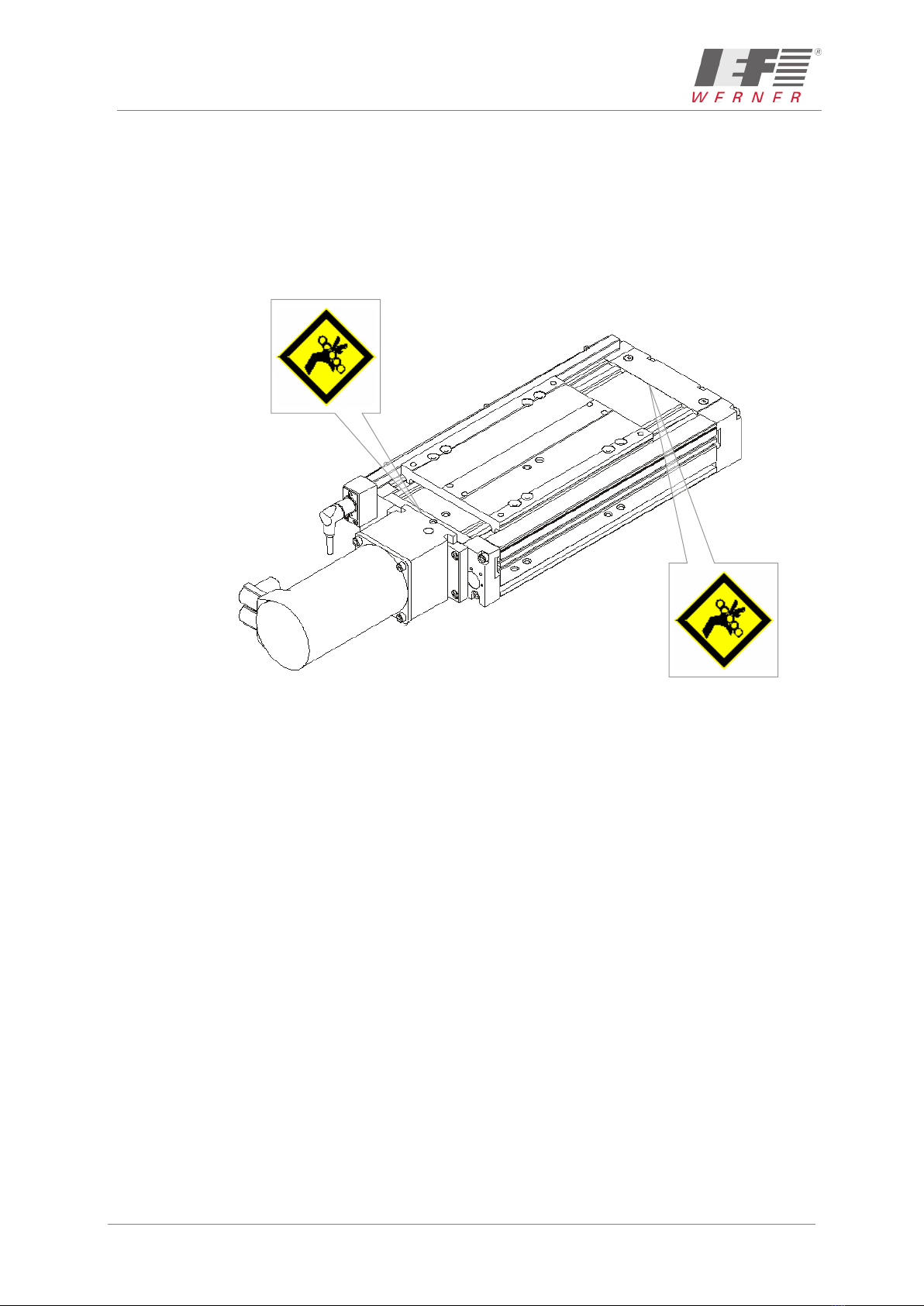
1.3 Special hazard warnings
In addition, this translation of Original User's Manual also contains the following special
hazard warning:
DANGER OF CRUSHING
These places of the components pose the danger of crushing limbs in
operation.
March 2019 Translation of the original instructions Intended use
MAN_EN_1039740_profiLINE140_R3d.docx profiLINE 140 Page 7 of 48
2 Intended use
The profiLINE 140 movement unit (see Figure 1) is a precise, linear adjustment unit with
spindle drive that is used in the commercial area as an attachment part in connection with
other components. In combination with many standardised assembly elements, as well as the
other movement units of IEF-Werner GmbH, it can be used to build complex multi-axis
positioning systems as well.
Figure 1: Module profiLINE 140
Area of application of the module profiLINE 140:
•Component insertion systems
•Palletising systems
•Loading and unloading stations
•Manipulators for the packaging industry
•etc.
2.1 Reasonably foreseeable misuse
The linear module profiLINE 140 is not to be used for certain applications such as the
transport of persons and animals or as a pressing/bending device for cold working of
metal.
Use of the linear module without additional measures is also not possible in special fields of
application, such as the chemical or food industry or in explosive atmospheres.
In case of doubt, consult the manufacturer.
Assembly instructions Translation of the original instructions March 2019
Page 8 of 48 profiLINE 140 MAN_EN_1039740_profiLINE140_R3d.docx
3 Assembly instructions
3.1 Installation position
The installation position is optional, i.e. the profiLINE 140 movement unit can be installed
horizontally as well as vertically.
CAUTION
With the vertical installation position, use only motors with spring-operated
brake to prevent the lowering of the drive in de-energized condition!
3.2 Motor installation
CAUTION
Wire the motors according to the motor data sheet.
When using customer-specific motors, inquire at the respective manufacturer
with which cable the motor has to be connected.
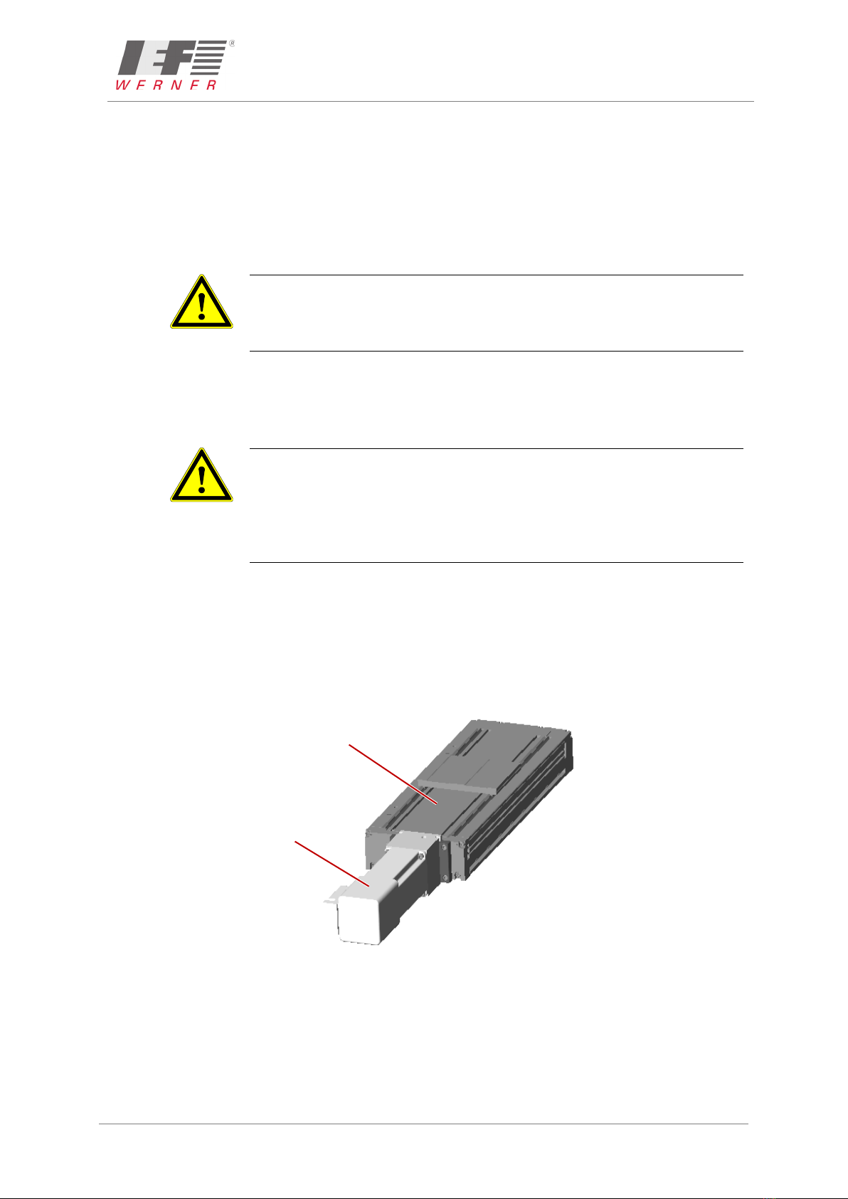
3.2.1 Axial motor installation
The carriage unit permits installation of the motor on the spindle extension via an axial motor
flange (adapter flange). The motor shaft is coupled with the spindle shaft by means of a
pluggable coupling. To centre the motor flange, the ball bearing of the floating spindle bearing
is used. Additional pinning of the motor flange with the end plate is not required.
Figure 2: Carriage unit with axial motor installation
Carriage unit
Motor
March 2019 Translation of the original instructions Assembly instructions
MAN_EN_1039740_profiLINE140_R3d.docx profiLINE 140 Page 9 of 48
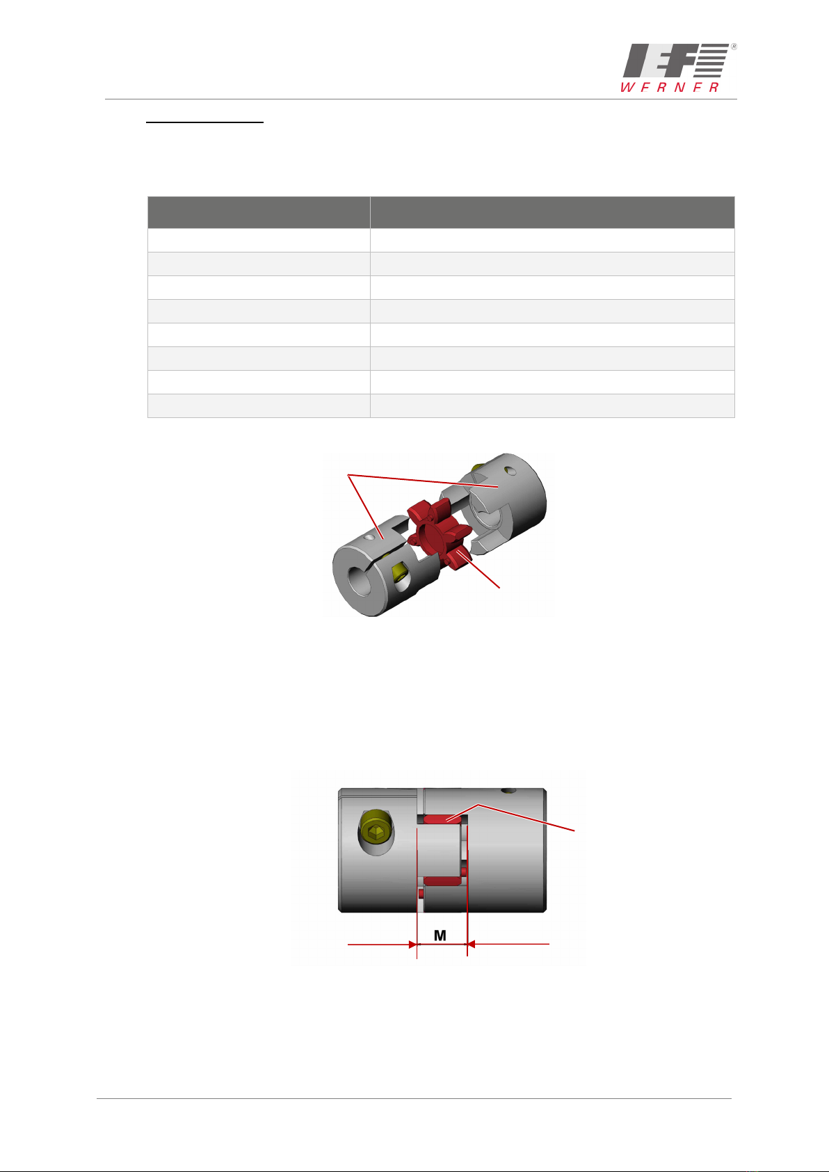
3.2.1.1 Pluggable coupling
The pluggable coupling system consists of the spindle coupling hub, the motor coupling hub
and an elastic ring gear.
The following hubs are available:
Motor shaft diameter Motor coupling hub article number
10 1064071
11 1064073
12 1064074
14 1064075
15 1064076
16 1064077
19 1064123
20 1064078
Different motor shaft diameters are available on request
Figure 3: Pluggable coupling
NOTE When installing the coupling, special care must be taken not to load the
elastic ring gear with axial pressure. It has to be ensured that the installation
dimension "M" =16 mm is observed in the installed condition. Light greasing
can reduce the axial installation force.
Figure 4: Coupling with installation dimension
Motor or
spindle coupling hub
Elastic ring gear
(E.g. No.: 1064079)
Elastic ring gear
M = 16 mm
Assembly instructions Translation of the original instructions March 2019
Page 10 of 48 profiLINE 140 MAN_EN_1039740_profiLINE140_R3d.docx
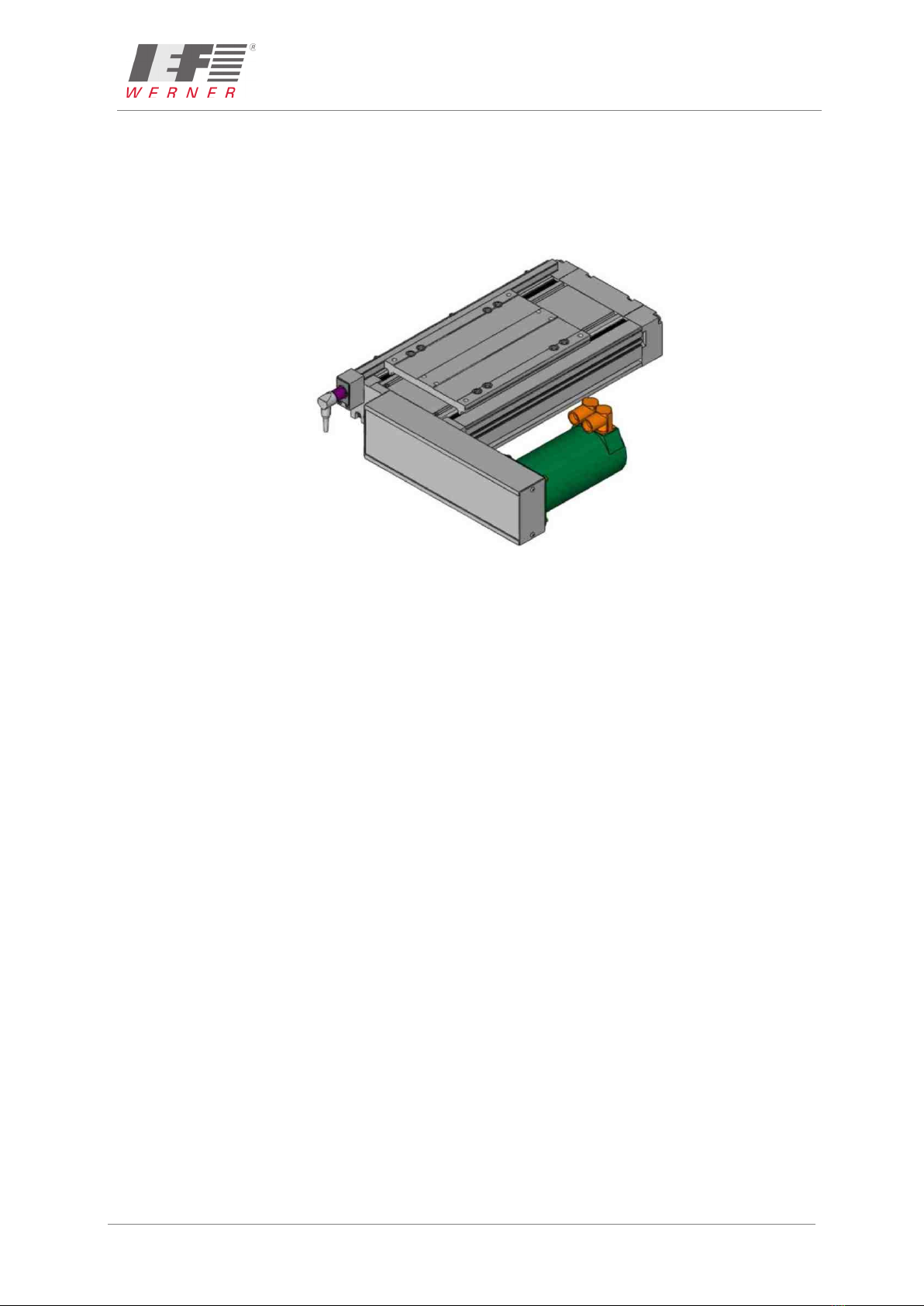
3.2.2 Motor installation via offset gearbox flange
The advantages of this installation variant are:
•Shorter overall length
•Gear reduction
•Adaptation to specific customer installation conditions with 4 possible installation variants
Figure 5: Motor installation via offset gearbox flange
NOTE For an overview of the different motor installation variants, see the section
Motor installation variants, Page 38.

March 2019 Translation of the original instructions Assembly instructions
MAN_EN_1039740_profiLINE140_R3d.docx profiLINE 140 Page 11 of 48
3.2.2.1 Overview of reduction ratios
Transmission
i =
Toothed disc
of motor
Toothed disc
of spindle
Max.
motor shaft*
Belt length
[mm]
Distance
between axes
[mm]
Preferred series
1 : 1 32 32 16 330 85
1 : 1 32 32 16 340 90
1 : 1 32 32 16 375 107.50
1 : 1 32 32 16 450 145
1 : 1 32 32 16 500 170
1 : 1 40 40 20 375 87.5
1 : 1 40 40 20 390 95
1 : 1 40 40 20 480 140
1 : 1 40 40 20 525 162.5
2:1 16 32 14 300 89.09
2:1 16 32 14 305 91.62
2:1 16 32 14 330 104.22
2:1 16 32 14 390 134.4
2:1 16 32 14 420 149.46
2:1 16 32 14 450 164.51
2:1 20 40 16 330 88.57
2:1 20 40 16 340 93.65
2:1 20 40 16 420 134.06
2:1 20 40 16 450 149.15
2:1 20 40 16 480 164.23
2,5:1 16 40 14 330 93.04
2,5:1 16 40 14 420 138.68
2,5:1 16 40 14 480 168.92
Different transmission ratios or distances between axes on request
* Plain motor shaft possible

Assembly instructions Translation of the original instructions March 2019
Page 12 of 48 profiLINE 140 MAN_EN_1039740_profiLINE140_R3d.docx
3.3 Transverse installation
Two methods are available for the transverse mounting of the profiLINE 140 movement units
(see the following sections).
3.3.1 Mounting of basic body on carriage
The transverse mounting is performed by means of two clamping rails, article No.: 1010173.
The overall height of the transverse mounting is 140 mm.
Figure 6: Basic body on carriage
3.3.2 Mounting of carriage on carriage
The transverse mounting is performed by means of an adapter plate, article No.: 1010169 as
well as two clamping rails article no.: 1010173. The overall height of the transverse mounting
is 155 mm (incl. adapter plate).
Figure 7: Carriage on carriage
March 2019 Translation of the original instructions Assembly instructions
MAN_EN_1039740_profiLINE140_R3d.docx profiLINE 140 Page 13 of 48
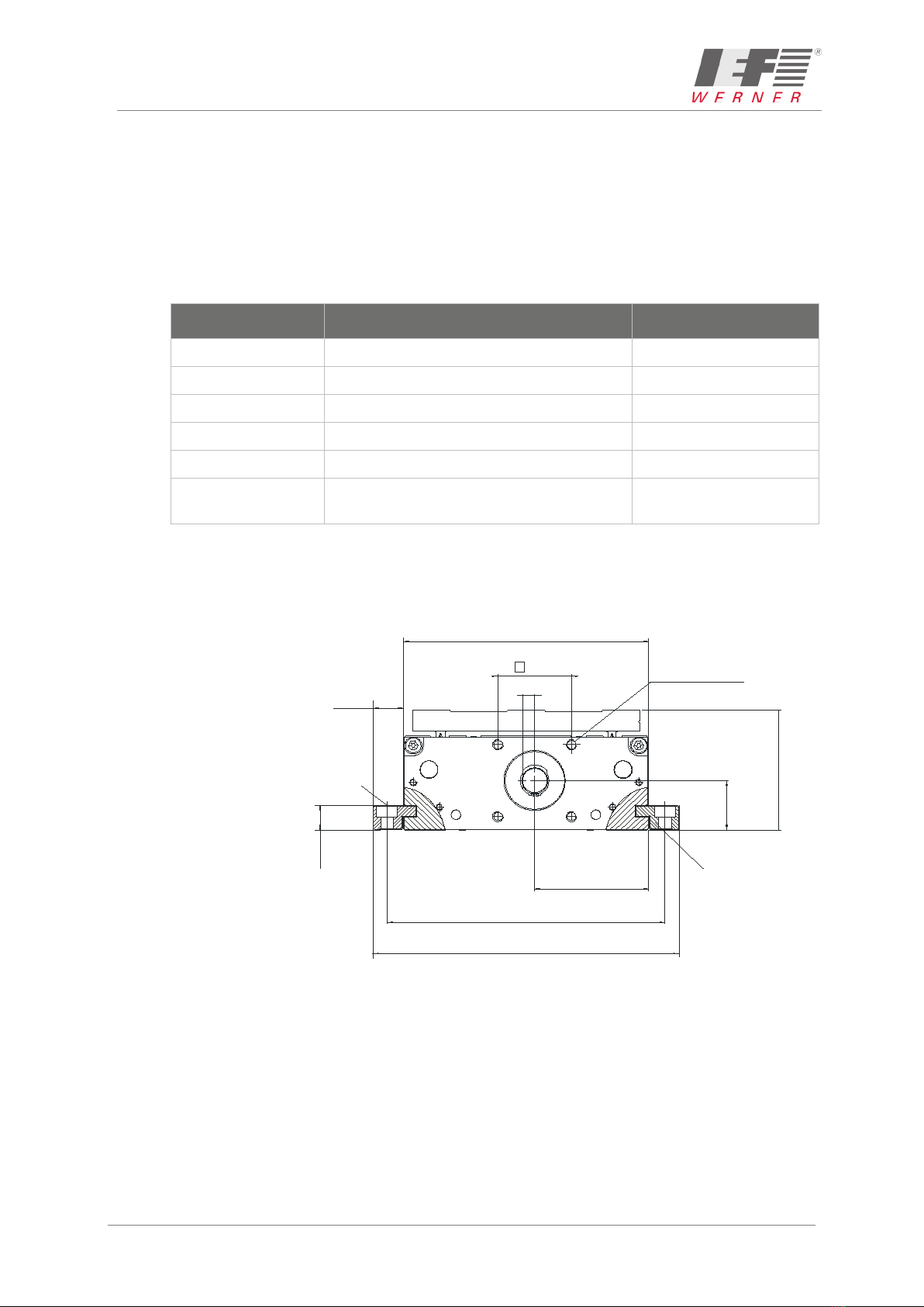
3.4 Attachment
The profiLINE 140 movement unit is attached to a level installation surface with clamping
profiles. We recommend using drilled attachment holes with a spacing of 80-120 mm. The
basic body has four mating holes to make possible a reproducible position.
If the attachment with clamping profiles is not possible, drilled attachment holes in the basic
body can also be made. Please contact us in this case.
The following clamping elements are available for attachment (see, e.g. Clamping rail M105
(Part No.: 1010173), page47):
Part No. Designation Length [mm]
220702 Type 16 clamping element 16
28674 Type 105 clamping element 105
220702 Type 140 clamping element 140
1010173 Clamping element (transverse mounting) 130
1019192 Clamping profile, yard goods Length of the basic unit
Clamping profiles according to customer
drawing
NOTE The installation area has to be a flat surface.
Any deviations from an ideal flat plane directly affect the processing
precision.
Figure 8: Attachment of profiLINE 140
159
70
29
140,0
65,2
42
54 x M6 x 10
Senkung DIN 74 - Km 6
Spannleiste
175
17,5
14,3
Countersink DIN 74 – Km 6
Clamping bar

Assembly instructions Translation of the original instructions March 2019
Page 14 of 48 profiLINE 140 MAN_EN_1039740_profiLINE140_R3d.docx
3.4.1 Installation of actuators
The actuators (cylinders, pick-up modules, etc.) that are to be installed on the profiLINE 140
movement unit can be attached via the drilling pattern on the carriage. Six drillings (M6) are
available for the attachment (see Figure 9).
Figure 9: Drilling pattern
CAUTION
During attachment, observe that the maximum screw-in depth of 9 mm is not
exceeded because this would lead to severe damage to the guide system.

March 2019 Translation of the original instructions Assembly instructions
MAN_EN_1039740_profiLINE140_R3d.docx profiLINE 140 Page 15 of 48
3.4.2 Pinning
The profiLINE 140 movement unit provides the possibility to pin a transverse mounting or a
customised installation without additional tools (drill, reamer) in a reproducible manner. For
this purpose, four hardened drill bushings are located in the short
carriage section.
Two drill bushings are firmly pressed in, two other drill bushings are inserted in a floating
manner in larger drillings. A fixed bearing and a floating bearing are arranged diagonally. The
part to be pinned requires a firmly defined drilling pattern for the mating holes that corresponds
to the drilling pattern in the short carriage section.
During installation and pinning, one of these floating drill bushings is embedded with special
two-component adhesive (article No.: 1027620) in the floating bearing. During installation of
the alignment pins, the drill bushing is optimally aligned with the alignment pins of the part to
be pinned. This type of pinning permits subsequent "fine adjustment" of the transverse
mounting within one hour. The adhesive hardens fully within 24 hours.
Figure 10: Drill bushings of profiLINE 140
Scaled drawing for
alignment pins Tolerance Drilled hole Article no. of drill bushing
102 x 102 ±0,01 6 H7 627122
Drill bushings
Alignment pin

Assembly instructions Translation of the original instructions March 2019
Page 16 of 48 profiLINE 140 MAN_EN_1039740_profiLINE140_R3d.docx
3.5 Wiring
3.5.1 Motors
CAUTION
The electrical connection of the motors is performed according to the motor
data sheet. For customer-specific motors, the data sheet must be requested
from the respective manufacturer and the motor connected accordingly.
3.5.2 Initiators
Inductive proximity switches (PNP normally closed contacts, green switch operating point)
are used as standard stroke limit switches
CAUTION
These stroke limit switches are not safety limit switches according to
EN60204-1.
Optionally, an additional reference point switch (PNP normally open contact, red switch
operating point) can be used. An LED is available for detection of the switch status. Initiators
and cables are installed in an aluminium profile and routed centrally to a plug. The aluminium
profile can be built into the carriage or be externally attached.
3.5.2.1 Technical data of initiators
Parameter Value
Operating voltage (10...30) VDC
Operating voltage residual ripple < 10 %
Current load capacity I
a
≤150 mA
Voltage drop at I
a
max. ≤3.5 V
Switching frequency ≤1 kHz
Own current consumption ≤10 mA
Nominal switching distance on steel 2 mm
Switching hysteresis (H) (3...15) %
Reproducibility (Rmax) ±3%
Operating temperature (-25 ... +70) °C
Protection class IP 67
Short-circuit proof
(response value for short-circuit protection 160mA) Yes
Protected against polarity reversal Yes
Switch dampened LED off
Switch not dampened LED lit
March 2019 Translation of the original instructions Assembly instructions
MAN_EN_1039740_profiLINE140_R3d.docx profiLINE 140 Page 17 of 48
Figure 11: Electrical connection of PNP normally closed contact
Figure 12: Electrical connection of PNP normally open contact
1
2
3
5
4
Pin-no.
1
2
3
4
5
assignment
+ 24 V
limit switch -movement
0 V
limit switch +movement
Reference switch
IEF-cable
brown
green
white
yellow
grey
Figure 13: Plug assignment, view of pins
4
5
LED
active area
Figure 14: Initiator
Assembly instructions Translation of the original instructions March 2019
Page 18 of 48 profiLINE 140 MAN_EN_1039740_profiLINE140_R3d.docx
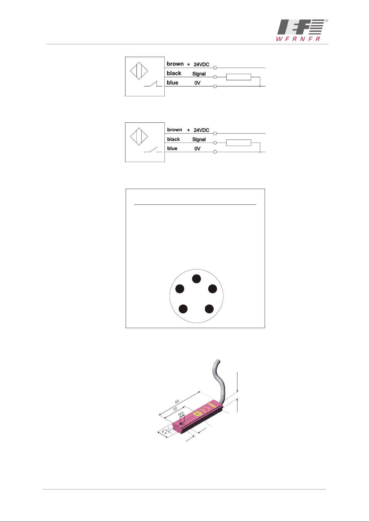
3.5.2.2 Installation of initiators
Initiators and cables are installed in an aluminium profile and routed centrally to a plug. The
aluminium profile can be built into the carriage or be externally attached.
Figure 15: Installation of initiators
No. Designation Article no.
1 Aluminium strip 1003692
2 Clip strip 028668
3 Limit switch holder 028585
4 Threaded pin M4 030887
5 Initiator PNP normally closed
contact
025165
5 Initiator PNP normally open
contact
726744
12 Screw M4 x 14 DIN 7984 1016016

March 2019 Translation of the original instructions Assembly instructions
MAN_EN_1039740_profiLINE140_R3d.docx profiLINE 140 Page 19 of 48
3.5.2.3 External installation of the initiators
External installation of the initiators is possible on both sides of the movement unit
(see Figure 16).
Figure 16: External installation of the initiators (Zn; 1010438)
No. Designation Article no.
1 Aluminium strip 1003692
7 Holder 1008967
8 Adapter piece 1006140
9 Cover 1006139
10 Connector 725163
11 Retaining plate 025626
12 Screw M4 x 16 DIN 7984 626061
13 Screw M4 x 30 DIN 912 626485
14 Screw M3 x 6 DIN 7380 626164
101 Screw M4 x 12 DIN 912 656836
102 Holder 1008969
103 Nut M4 DIN 439 626953

Assembly instructions Translation of the original instructions March 2019
Page 20 of 48 profiLINE 140 MAN_EN_1039740_profiLINE140_R3d.docx
3.5.2.4 Integrated installation of the initiators
In case of integrated installation, the initiators are within the movement unit and are protected
against contamination or mechanical influences (see Figure 17).
9
8
11
10
13
1
12
Figure 17: Integrated installation of the initiators
No. Designation Article no.
1 Aluminium strip 1003692
8 Adapter piece 1006140
9 Cover 1006139
10 Connector 725163
11 Retaining plate 25626
12 Screw M4 x 14 DIN 7984 1016016
13 Screw M4 x 30 DIN 912 626485
NOTE At integrated installation of the initiators, particularly observe that only screws
according to DIN 7984 (flat-head) are used, because the guide carriages
would otherwise be damaged.
This manual suits for next models
1
Table of contents
Popular DC Drive manuals by other brands


SEW-Eurodrive
SEW-Eurodrive MOVITRAC B System manual

Lenze
Lenze L-force 8400 Series Mounting instructions

Danfoss
Danfoss VLT AQUA Drive FC 202 Design guide

Danaher Motion
Danaher Motion Superior SLO-SYN SS2000MD4-M installation instructions

Automationdirect.com
Automationdirect.com DURApulse GS10 quick start guide

EACON
EACON EC6000 Series quick guide