Japa 485 User manual

ENGLISH
japa 485
User manual
TR –Tractor drive
TRE –Electricity and tractor drive
6.0t
8.0t

TABLE OF CONTENTS
1. Introduction............................................................................................................................2
1.1 Customer registration ......................................................................................................2
1.2 Declaration of conformity.................................................................................................3
1.3 Purpose of use.................................................................................................................4
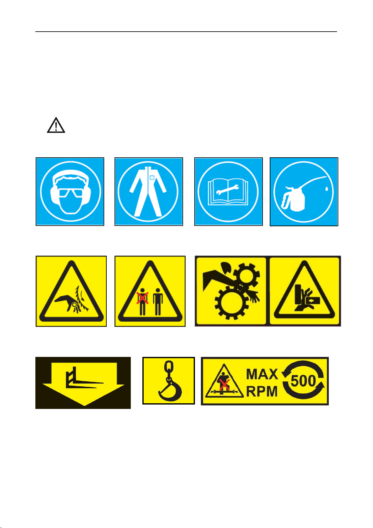
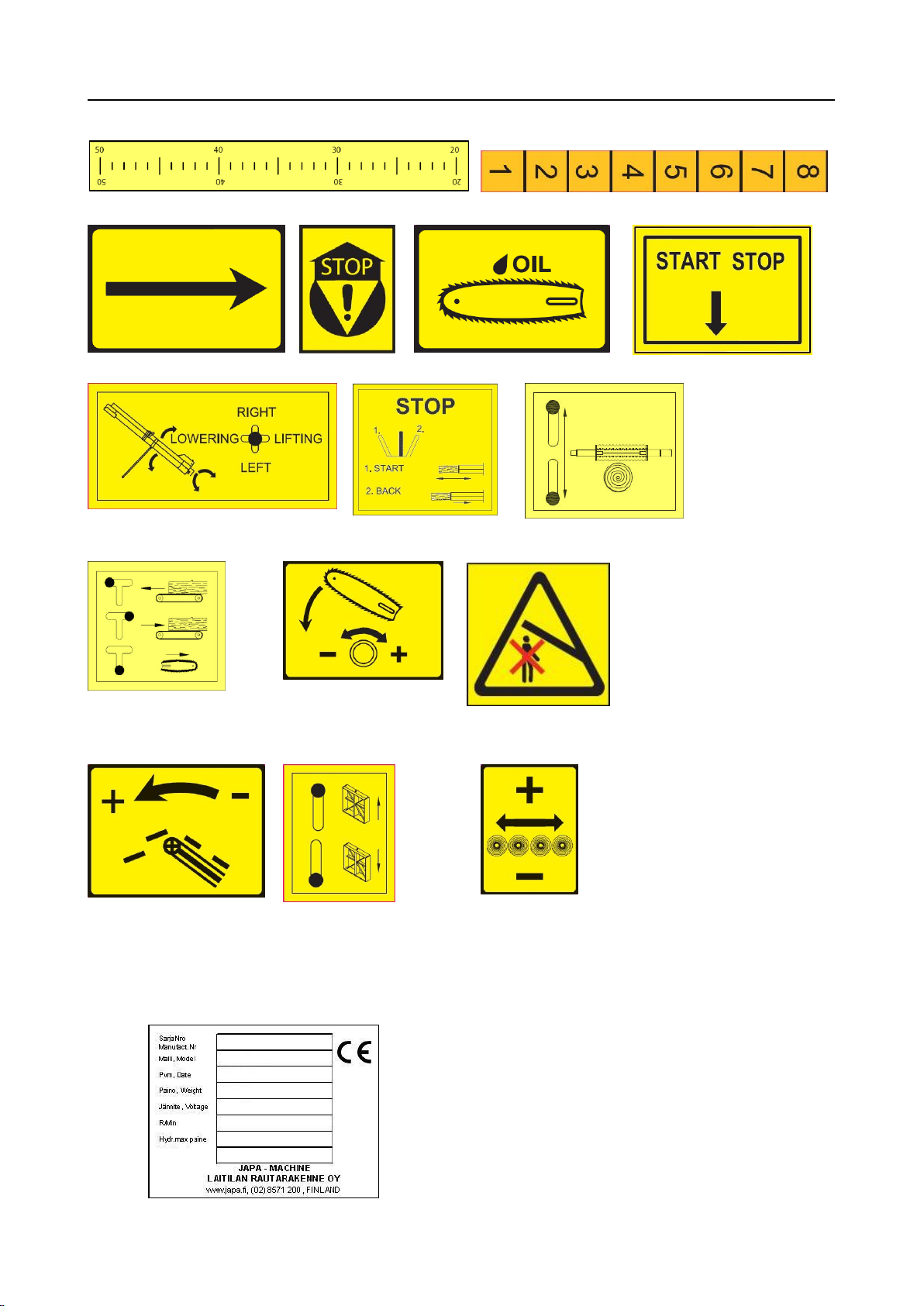
1.4 Instruction and warning labels on the machine ...............................................................4
1.5 The machine’s type plate.................................................................................................5
1.6 Machine models...............................................................................................................6
1.7 Safety instructions............................................................................................................7
1.8 Noise level and vibration..................................................................................................8
1.9 Guarantee terms..............................................................................................................9
2. Installation of the machine .................................................................................................10
2.1 Delivery inspection.........................................................................................................10
2.2 Main components of the machine..................................................................................10
2.3 Lifting and transporting the machine..............................................................................11
2.4 Working position ............................................................................................................12
2.5 Connecting the power source........................................................................................13
2.6 Transport position..........................................................................................................13
2.7 Connections...................................................................................................................14
3. Operating the machine........................................................................................................15
3.1 Acknowledging the hazards and responsibilities involved.............................................15
3.2 Before use......................................................................................................................15
3.3 Safety mechanism .........................................................................................................15
3.4 Control panel..................................................................................................................16
3.5 Cutting device................................................................................................................17
3.6 Blade lubrication ............................................................................................................18
3.7 Splitting device...............................................................................................................19
3.8 Replacing the splitting knife...........................................................................................20
4. Accessories..........................................................................................................................21
4.1 Splitting knives...............................................................................................................21
4.2 Dust extractor.................................................................................................................21
4.3 Hydraulic timber deck ....................................................................................................21
4.4 Cleaning drum................................................................................................................22
4.5 Sacking rack ..................................................................................................................22
5. Maintenance and troubleshooting.....................................................................................23
5.1 Maintenance table..........................................................................................................23
5.2 First maintenance ..........................................................................................................24
5.3 Daily maintenance (10 hrs)............................................................................................24
5.3.1 Maintaining the cutting blade ........................................................................................25
5.3.2 Maintaining the splitting knife........................................................................................26
5.4 Monthly maintenance (200 hrs).....................................................................................26
5.4.1 Adjustments of the cutting device .................................................................................28

5.4.2 Adjustments of the splitting device................................................................................29
5.4.3 Adjustment of the speeding valve.................................................................................30
5.4.4 Adjusting the conveyor’s relief valve .............................................................................31
5.4.5 Adjusting the switching of splitting power .....................................................................31
5.5 Annual maintenance (1,000 hrs)....................................................................................31
5.5.1 Extended maintenance interval.....................................................................................33
5.5.2 Lubricant table...............................................................................................................33
5.6 Storage ..........................................................................................................................33
5.7 Maintenance log.............................................................................................................33
6. Troubleshooting...................................................................................................................34
7. Product disposal..................................................................................................................36
8. Technical specifications .....................................................................................................37
8.1 Electric motor connection diagram (TRE models).........................................................38
8.2 Hydraulics diagram........................................................................................................40

japa 485 User manual
Translation 2 485 1.0-2014
1. Introduction
Laitilan Rautarakenne Oy (JAPA) is a Finnish company engaged in extensive product development. Our goal
is to produce simple, reliable and structurally durable machines with a long service life. If you use your JAPA
machine correctly and maintain it according to the instructions in this manual, it will serve you efficiently for a
long time. If you have questions and would like to discuss them in detail, please contact our retailer or us
directly.
CONGRATULATIONS ON PURCHASING A NEW JAPA FIREWOOD PROCESSOR!
This manual is intended for operators with the appropriate expertise. For this reason, operators are expected
to have the general knowledge and basic skills required for working with this kind of machinery. Familiarise
yourself with the manual before installing the machine and beginning operation. Carefully study the
machine’s features and safety equipment before operation. Always keep this manual with the machine. The
instructions, descriptions and technical specifications in this manual are based on the latest information with
regard to the workings of the machine at the time of printing. However, the manufacturer develops and
updates the machine continuously and therefore reserves the right to change the machine’s features and
safety-related properties without separate notification.
In order to receive quick and efficient assistance when ordering spare parts and encountering any possible
fault situations, you must indicate the information on the machine’s type plate to the retailer or service
technician. Write down the type plate information in the reserved section on this page to ensure that it is
readily available at all times. If you cannot find a solution to a problem on your own, please contact the
retailer, who will then resolve the matter with the manufacturer.
We at JAPA are confident that you will be satisfied with your new firewood processor. It meets all the safety
requirements imposed by the European Union and carries the relevant CE label.
1.1 Customer registration
Laitilan Rautarakenne Oy utilises an EXTRANET service where the owners and operators can register their
machines. The site contains useful information, such as user manuals and spare parts manuals.
https://info.japa.fi/
FILL IN THE TYPE PLATE INFORMATION AND THE RETAILER’S CONTACT INFORMATION:
Serial number:
Delivery date:
Retailer:
Contact person:
Address:
Telephone:

japa 485 User manual
Translation 3 485 1.0-2014
1.2 Declaration of conformity
Manufacturer:
Laitilan Rautarakenne Oy
Kusnintie 44
FI-23800 Laitila, Finland
Tel. +358 2857 1200
Fax +358 2857 1201
Web: www.japa.fi
Person responsible for the technical file: Ville Kairus
The declaration applies to the following machines:
JAPA 485 TR 24 t Tractor drive
JAPA 485 TRE 24 t Tractor/electrical drive
The following directives have been observed in the construction of each machine:
Machinery Safety Directive 2006/42/EC brought into effect through Government Decree 400/2008.
Conformity evaluation conducted by:
MTT Mittaus ja standardisointi (Vakola)
Vakolantie 55
FI-03400 Vihti
Laitila 1 February 2014
Laitilan Rautarakenne Oy
Henri Nurminen
Managing Director

japa 485 User manual
Translation 4 485 1.0-2014
1.3 Purpose of use
The JAPA 485 is an efficient, safe and easy-to-use firewood processor for cutting and splitting firewood. The
hydraulic 22” chainsaw cuts the logs safely and quickly up to a diameter of 48 cm. The saw chain is
lubricated with a separate system for supplying saw chain oil. The saw chain only rotates during sawing,
which makes working with the machine safer and quieter. The cutting length can be freely adjusted between
20 and 66 cm. The log length limiter is hydraulic. The machine can be equipped with a knife that splits the
logs into six, eight or twelve pieces. We place great emphasis on the reliability of our products; the Japa 485
does not contain any V-belts!
ONLY ONE PERSON MAY OPERATE THE MACHINE AT A TIME!
1.4 Instruction and warning labels on the machine
Fork lift point
Lifting point
Beware of the rotating shaft! The maximum allowed rotation
speed and direction of the power take-off shaft
Wear ear protection and
protective goggles.
Wear suitable work clothing,
gloves and shoes.
Read the user manual before
operation and maintenance.
Check the condition and
safety equipment of the
machine before operation.
Beware of the rotating cutting
blade!
Only one user at a time. Ensure
that no other persons are in the
working area.
Risk of crushing!
Beware of the splitting knife
and the splitting mechanism.

japa 485 User manual
Translation 5 485 1.0-2014
Log length measurement scale
Height adjustment scale for the splitting knife
Rotation direction of the electric
motor
Emergency stop
Tank for blade lubrication oil
Electrical drive control
Lifting and turning of the conveyor
Starting, stopping and
reversing the splitting
mechanism
Lifting and lowering the
wood gripper
Cutting and input conveyor
control
Adjustment of the saw bar
lowering speed.
Do not walk under the
conveyor! The safety distance
is 5 m
Speed adjustment for the output
conveyor
Splitting knife adjustment
Control for additional
hydraulics
1.5 The machine’s type plate
The machine’s type plate is located behind the machine, on the tractor side.
Serial number
Machine type
Production year and date
Weight of the machine
Voltage (TRE models)
Maximum rotation speed of power take-off
Maximum pressure of hydraulics
Diameter of the cutting blade/blade opening diameter
Name and address of manufacturer
Terä, Blade

japa 485 User manual
Translation 6 485 1.0-2014
1.6 Machine models
JAPA 485 TR 24 t Tractor drive
JAPA 485 TRE 24 t Tractor/electrical drive
Features:
Hydraulic 2.5 m input conveyor with series connection
x
Input conveyor reverse capability
x
Hydraulic log length measuring device
x
Additional hydraulics for the hydraulic timber deck, for example
x
Hydraulic 22” chainsaw with a separate chain lubrication system
x
Cutting control with a joystick
x
8-way splitting knife
x
6-way splitting knife
o
12-way splitting knife
o
Hydraulic knife lifter
x
Hydraulic 4 m output conveyor with turning device
x
Speed adjustment for the output conveyor
x
Hydraulic oil cooler
x
230V/10A mains power socket
TRE
Hydraulic timber deck [JA4790]
o
Dust extractor, 230V electrical drive [JA47940]
o
Dust extractor, hydraulic drive [JA47950]
o
x = standard equipment
o = accessory

japa 485 User manual
Translation 7 485 1.0-2014
1.7 Safety instructions
These safety instructions are general in nature. When handling the machine, you must take into
account all other relevant instructions concerning health and safety, road traffic regulations regarding
transportation, as well as the provisions of the general legislation. Observing these instructions helps to
prevent accidents.
The machine may only be used by persons who have familiarised themselves with the manual and the
operation of the machine. The operator must not be under the influence of alcohol or narcotic
substances. The requirements placed on the operator, as well as the minimum age of 18 required to
operate the machine, must be taken into account.
Study the machine’s safety and installation instructions carefully, along with the operation and control
functions, before installing and operating the machine.
General provisions:
The machine must be used solely for making firewood.
Only one person may operate the machine at a time.
Ensure that no unauthorised persons are in the working area. The danger zone is 10 m.
Always check the condition of any possible power cables.
Always use approved eye and ear protection.
Clean and maintain the machine on a regular basis.
Always stop the machine before maintenance and, if the machine is tractor-driven (TR),
disconnect the cardan shaft. If the machine features an electrical drive (E), disconnect the
power cable.
Check the operation of the safety equipment. Do not use the machine if part of the mechanism
is not functioning properly.
The machine may only be transported in the transport position. This is the responsibility of the
driver.
If the firewood processor is to be transported on the road, the widest parts of the machine must
be marked with alternating red and yellow stripes. The markings can be implemented with flags
or tape. The widest parts of the machine must also be equipped with forward-facing white and
backward-facing red reflectors with either EC or E type approval. Attention must be paid to
sufficient front axle weight.
The machine can only be used to process clean wood (no nails, screws, sand, etc.)
Working area:
Select a level and solid working area.
Keep the area clean and free of obstructions.
Ensure that the ground or floor is not slippery near the machine.
Do not use the machine indoors, as the dust may enter your airways or cause a fire hazard.
Only use the machine with sufficient lighting: daylight is recommended.
Place the machine in the working position. Always check the safety devices before starting the
machine.
During operation:
Take extreme care when cutting knotty or bent wood.
When sawing incorrectly, the log may spin, causing injury or machine damage.
Careless sawing or splitting may cause unexpected hazards.
Ensure that the PTO shaft is undamaged and attach the shaft guard chain to the machine.
Avoid unnecessary lifting by using a suitable log rack.
Do not lift logs directly onto the input table with a loader.
DO NOT LEAVE A RUNNING MACHINE UNSUPERVISED!

japa 485 User manual
Translation 8 485 1.0-2014
1.8 Noise level and vibration
The JAPA 485 firewood processor’s sound power level, as specified in standard EN ISO 3744:2010,
during a work cycle is 109 dB, while the maximum sound pressure at the operator’s position during a
work cycle is 95 dB. The estimated standard deviation of the reproducibility of the sound power level is
1.5 dB.
If the machine is driven with a tractor, the tractor may be the dominant source of noise in the working
area. Always use sufficient ear protection –earmuffs or plugs. We recommend using a logger’s helmet.

japa 485 User manual
Translation 9 485 1.0-2014
1.9 Guarantee terms
The guarantee is valid for the original buyer for 12 months, starting from the date of purchase, but for no
more than 1,000 operating hours.
In guarantee matters, always contact the machine’s seller before undertaking any procedures.
A guarantee demand must be issued to the seller in writing immediately upon discovery of a defect. If the
defect concerns a damaged part or component, please send a photograph of the damaged part or
component to the seller, if possible, so the fault can be identified. When submitting a guarantee claim, the
buyer must always include the type and serial number of the machine and present a receipt that includes
the date of purchase. Guarantee claims must be submitted to an authorised retailer.
Guarantee terms come into force when you register your customership in the extranet service found on our
website.
The guarantee covers
Parts damaged in normal use due to faults in material or manufacture.
Reasonable expenses caused by repairing a fault in accordance with the agreement between the
seller or buyer and manufacturer. Faulty parts will be replaced with new ones. A faulty part or parts
replaced due to a material fault should be returned to the manufacturer through the retailer.
The guarantee does not cover:
Damage caused by normal wear and tear (for example blades, mats and belts), improper use or
use contrary to the instruction manual.
Damages caused by negligence of maintenance or storage procedures detailed in the instruction
manual.
Damages caused during transport.
Cutting blades, V-belts and oil, and normal adjustment, care, maintenance or cleaning procedures.
Defects in a machine to which the buyer has carried out or commissioned structural or functional
changes to the degree that the machine can no longer be considered equivalent to the original
machine.
Other potential costs or financial obligations resulting from the procedures mentioned above.
Indirect costs.
Travel costs resulting from guarantee repairs.
The guarantee for parts replaced during the guarantee period of the machine expires at the same
time as the machine’s guarantee.
The guarantee is void if the ownership of the machine is transferred to a third party during the
guarantee period.
The guarantee is void if any of the machine’s seals have been broken.
If a fault or defect reported by the customer is found to not be covered by the guarantee, the manufacturer
has the right to charge the customer for the pinpointing and possible repair of the fault or defect in
accordance with the manufacturer's current price list.
This guarantee certificate indicates our responsibilities and obligations in full and it excludes all other
responsibilities.

japa 485 User manual
Translation 10 485 1.0-2014
2. Installation of the machine
2.1 Delivery inspection
Inspect the machine immediately upon delivery. If the product has sustained damage in transit or it is
missing components, contact the transport company and retailer immediately.
2.2 Main components of the machine
1.
Output conveyor
6.
Blade guard
2.
Knife replacement winch
7.
Wood gripper
3.
Splitting area guard
8.
Control panel
4.
Front panel
9.
Input opening guard
5.
Log length measurement device
10.
Input conveyor
1
3
4
5
6
7
8
2
9
10

japa 485 User manual
Translation 11 485 1.0-2014
2.3 Lifting and transporting the machine
All JAPA 485 firewood processors feature fork lift and crane lifting points as well as CAT1 three-point lifting
device linkage.
A. Fork lift point
The fork lift slots are located on the bottom edge of
the frame on the front side of the machine.
B. Crane lifting point
The lifting logs (2 pcs) are located in the positions
indicated in the figure.
Before lifting, ensure the sufficiency and condition
of the equipment used. Also ensure that the lifting
straps and chains are firmly attached to the
machine before commencing the lifting operation.
C. CAT1 three-point lifting device linkage
The three-point linkage is located at the rear of the
machine.
First connect the lifting arms and then the push
arm. Ensure the arm connection is in place and lock
the device to the middle with the side limiters.
During tractor operation, always connect the
machine to the lifting devices and centre it with side
limiters.
The lifting force from the lifting device is 4 tonnes;
bear in mind the lightening of the tractor’s front
section.
LIFTING AND TRANSPORTING THE MACHINE IS ONLY ALLOWED IN THE TRANSPORT POSITION!
BEFORE LIFTING, ENSURE THAT NO OTHER PERSONS OR ANIMALS ARE WITHIN THE
MACHINE’S DANGER ZONE! MONITOR THE AREA AND ENSURE THAT IT STAYS EMPTY FOR THE
ENTIRE DURATION OF THE LIFTING!

japa 485 User manual
Translation 12 485 1.0-2014
2.4 Working position
Once you have transported the device to the working location, you can begin placing it in the working
position. Ensure that the foundation is solid and the legs stand firmly on the ground.
A. Open the locking latch of the extension table.
B. Lower the extension with the knife replacement
winch and place the support in the designated holes.
C. Detach the transport position chain from the slot.
D. Start the machine and lower the conveyor with the
hydraulics control valve.
E. Turn off the machine. Fold the conveyor straight.
This should be done by two people using the lifting
handles on the conveyor. Move the belt transport
support into the hole in the hinge, and lock the
joint.
F. Start the machine and use the hydraulics to lift the
conveyor into the working position.
Note the highest angle!
DO NOT WALK UNDER A CONVEYOR SUSPENDED BY HYDRAULICS!
DO NOT FOLD THE CONVEYOR EXTENSION WHILE THE MACHINE IS RUNNING
MAX.
45 °

japa 485 User manual
Translation 13 485 1.0-2014
2.5 Connecting the power source
The JAPA 485 firewood processor can be equipped with two different power sources and a combination
thereof.
A.1. TR –tractor drive
Connect the power take-off shaft. Note the highest
rpm and rotation direction.
Check the shaft cover and attach the fastenings
that prevent rotation.
Also ensure the shaft length; at least 100 mm
vertically with a 25 mm bottoming clearance.
Suitable cardan shafts include Binacchi
B6110CEA60A60, Bondioli & Pavesi
7C26044CE007007 and Ahlsell T19003697. The
cardan shaft does not require a safety switch.
A.2. TR –tractor drive
Connect the cable from the junction box to the
tractor’s light socket, and switch on the tractor’s
parking lights.
Remember to turn off the tractor lights after use.
B. E –electrical drive
Electric motor 15kW/400V/32A, connect only to a
fault current protected socket.
Note the motor’s correct rotation direction and the
reverser of the socket. The direction can be
changed by turning the disc in the middle of the
socket 180 °.
The correct rotation direction is indicated by the
arrow on the side of the electric motor. You can see
the rotating direction of the motor through the
electric motor’s cooling grille.
C. Electric start (TRE models)
I –start
O –stop
READ THE USER MANUAL BEFORE ACTIVATING THE MACHINE FOR THE FIRST TIME!
2.6 Transport position
The machine can be placed in the transport position by performing the steps in section 2.4 in reverse.
THE CONVEYOR MUST BE ALIGNED WITH THE MACHINE WHEN IT IS RAISED INTO THE
TRANSPORT POSITION!

japa 485 User manual
Translation 14 485 1.0-2014
2.7 Connections
Various hydraulically or electrically driven accessories can be connected to the Japa 485 firewood
processors.
A. Series connection of the input conveyor
A feed roller (JA4652 or JA4655), which operates
simultaneously with the input conveyor, is
connected to the series connection.
NOTE! If the device is used without a feed roller, a
loop hose must be connected to the series
connection.
B. Continuous output
Continuous output is required when using the
hydraulic dust extractor (JA47950) or cleaning drum
(JA475H).
NOTE! Also connect the overflow hoses of the
output conveyor to the overflow line with a T
branch.
NOTE! Always adjust the conveyor’s relief valve if
you connect or disable continuous output
accessories (5.4.4).
C. Additional hydraulics controlled with a
separate valve
Additional hydraulics can be used to control the
chain conveyor of the timber deck (JA46501), for
example.
D. Mains power socket (230V/10A)
The electrical dust extractor (JA47940) can be
connected to the machine’s power socket. If this is
done, the accessory will activate at the same time
as the firewood processor.
NOTE! MAX 2000 W
NOTE! TRE models

japa 485 User manual
Translation 15 485 1.0-2014
3. Operating the machine
3.1 Acknowledging the hazards and responsibilities involved
Operators of the machine must familiarise themselves with and observe the instructions in the user
manual. Incorrect operation of the machine (for example, removing the guards) may compromise the
operator’s safety. In these cases, the responsibility for the consequences rests with the operator.
3.2 Before use
Safe use of the machine requires adherence to the user manual and the instructions provided by the
instruction and warning labels. The operator is responsible for the operation and maintenance of the
machine and its safety device. Neglecting to maintain the machine or use the safety equipment may void
the guarantee. Ensure that you have familiarised yourself with the operation of the machine and its
functions.
1. Visually check that the machine has not been damaged.
2. Ensure that the machine has been installed firmly in place.
3. Check the machine for oil leaks.
4. Ensure that the machine’s power source is correctly connected.
5. Ensure that all of the machine’s components and guards are in place.
6. Check the machine’s hydraulic and blade oil levels and add oil if necessary.
7. Ensure that no unauthorised persons are in the danger zone.
8. Ensure that no unnecessary items have been left in the splitting or cutting area after transport,
for example.
9. Start the machine.
10. Check that the machine’s controls work as intended. The machine’s controls and their intended
operation are described in section 3.4.
11. Ensure that opening the splitting area guard stops the splitting motion and cutting blade
immediately if the guard is opened more than 20 mm (3.3).
12. Check that the hydraulic hoses are intact; pay particular attention to the hoses of the output
conveyor’s lifting cylinder.
3.3 Safety mechanism
The machine features a safety mechanism that prevents operation when the guard of the splitting section is
opened even slightly.
A. The safety mechanism stops the splitting and
prevents the rotation of the chainsaw immediately if
the guard is opened more than 20 mm.
If closed, the protective mesh also prevents the
opening of the blade guard.
The splitting motion stopped by the safety
mechanism will not start before it is reactivated.
DO NOT USE THE MACHINE IF THE SAFETY MECHANISM DOES NOT FUNCTION!
IF YOU NEED TO ADJUST THE SAFETY MECHANISM, SEE SECTION 1.9 GUARANTEE
TERMS.

japa 485 User manual
Translation 16 485 1.0-2014
3.4 Control panel
1. Speed adjustment for the output conveyor
2. Turning and lifting/lowering the output conveyor
3. Lifting and lowering the splitting knife
4. Adjustment of the saw bar lowering speed
5. Starting, stopping and reversing the splitting mechanism
6. Lifting the wood gripper
7. Control lever for the input conveyor and sawing
8. Control lever for hydraulics power take-off
9. Control lever for electrical drive (TRE model only)
1
2
3
4
2
5
6
2
7
8
9

japa 485 User manual
Translation 17 485 1.0-2014
3.5 Cutting device
The Japa 485 firewood processor is equipped with a hydraulic chainsaw, which only rotates during sawing.
The cutting device features an automatic chain tensioner. The cutting device is also connected to a safety
mechanism, which prevents the saw from rotating when the blade guard is open. The length of the log to
be cut can be adjusted freely between 20 and 66 cm.
To adjust the log length, move the hydraulic log
length limiter. The length is indicated by the scale.
Loosen the locking nuts that hold the hydraulics
valve in place and move the stop to the desired
length. Tighten the locking screws.
Input conveyor forward
Input conveyor reverse
Sawing
When the lever is pulled, the saw is activated and
begins its downward motion. To deactivate the saw
and return it to the upper position, release the
lever.
When feeding in new logs for sawing, push the
wood gripper lever up to raise the gripper and
make way for the logs. You can conveniently use
the wood gripper with the thumb of your sawing
hand while feeding in wood.
After this, the wood gripper will automatically hold
and feed timber during sawing and feeding. If
necessary, you can increase the gripper’s force by
pulling the lever down.

japa 485 User manual
Translation 18 485 1.0-2014
3.6 Blade lubrication
The Japa 485 firewood processor is equipped with a separate blade lubrication system. Ensure that there
is a sufficient level of lubrication oil through the sight glass. Add oil if necessary. The capacity of the blade
oil tank is 9 litres.
A. Blade lubrication system
1. Filler opening
2. Sight glass
DO NOT PLACE YOUR HAND NEAR THE CUTTING BLADE WHEN THE MACHINE IS
RUNNING!
DO NOT HOLD THE SAW HANDLE IN ONE POSITION LEAVING THE CHAIN RUNNING
CONSTANTLY!
USE PURE MINERAL OILS INTENDED FOR BLADE LUBRICATION ONLY.
DO NOT USE BIO OR WASTE OIL!
2
1
Table of contents