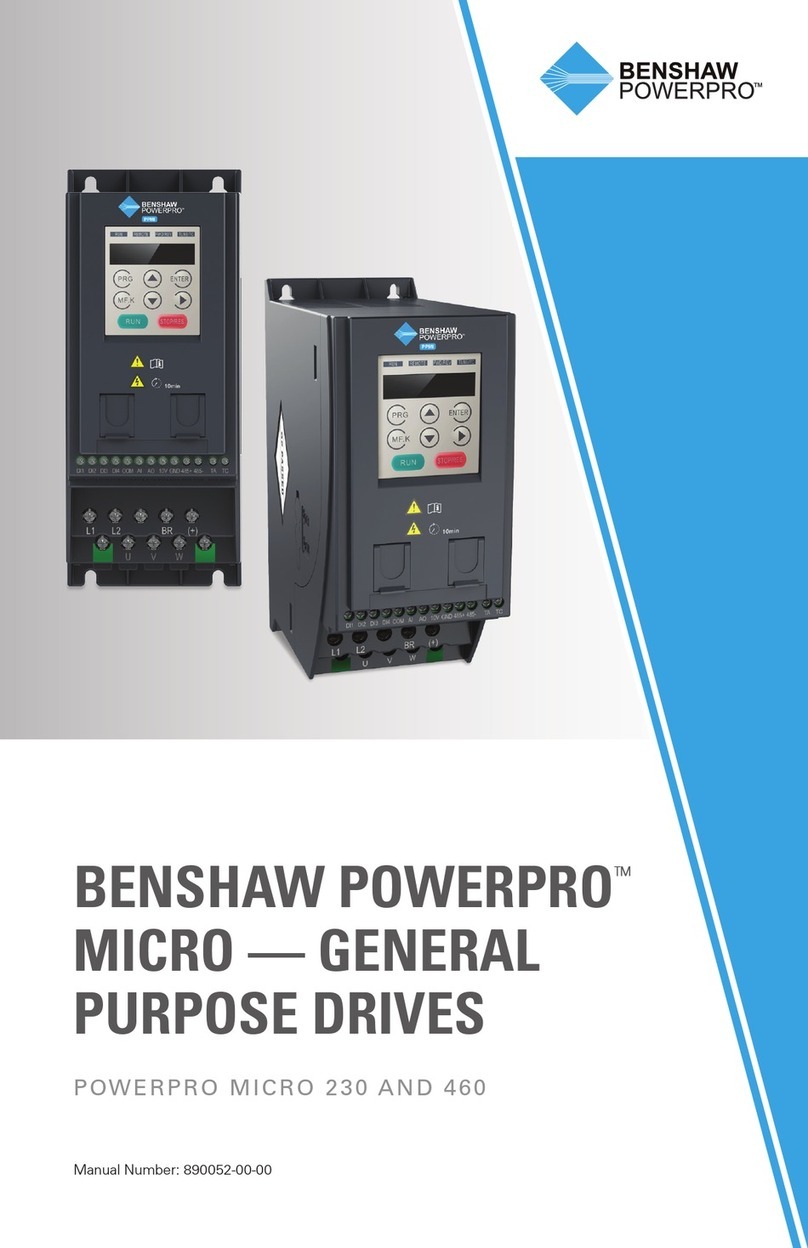
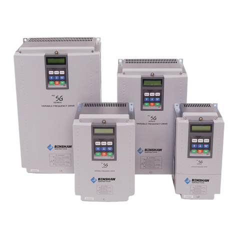
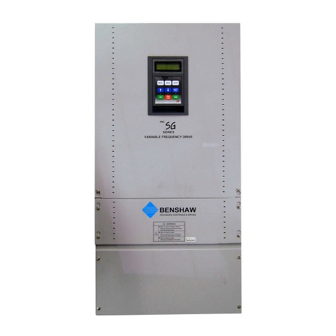
BENSHAW RSi H2P Series User manual

Page 1 of 2
RSi H2P
Series
Variable Frequency Drive
With
Pump Lead Lag Software
1.0 to 25 HP - 230V
1.0 to 800 HP - 460V
Instruction Manual
890053-02-00
© 2020 Benshaw Inc.
Benshaw retains the right to change specifications and illustrations in text without prior notification.
The contents of this document may not be copied without the explicit permission of Benshaw.


Page i
INDEX
INDEX........................................................................................................................................................i
1Introduction........................................................................................................................................1
1.1 Lead/Lag Descriptions................................................................................................................1
2Lead/Lag Characteristics...................................................................................................................2
2.1 Terminology and Definitions.......................................................................................................2
2.2 Characteristics of Lead/Lag Operation.......................................................................................2
3LCD Display/Keypad .........................................................................................................................3
3.1 Status .........................................................................................................................................3
3.2 Monitor Screen...........................................................................................................................3
3.3 HAND-OFF-AUTO Buttons - Operation......................................................................................4
3.4 Start/Stop Control.......................................................................................................................4
4Transducer and Communications Wiring...........................................................................................5
5Parameter Setup ...............................................................................................................................6
6Macro 2 Group (MC2)........................................................................................................................7
6.1 Additional Parameters................................................................................................................9
6.2 Related Parameters....................................................................................................................9
6.3 Control Related Parameters.....................................................................................................10
7Application Group 1, AP1 Parameter List........................................................................................11
8Application Group 1, AP1 Parameter Descriptions..........................................................................14
9Lead/Lag - Follow Lead...................................................................................................................22
9.1 Follow Lead - Conditions for Staging Lag Drives .....................................................................22
9.2 Follow Lead - Staging Details...................................................................................................22
9.3 Follow Lead - Conditions for De-staging Lag Drives................................................................23
9.4 Follow Lead - De-staging Details..............................................................................................23
10 Lead/Lag - Fixed Lag...................................................................................................................24
10.1 Fixed Lag - Conditions for Staging Lag Drives.........................................................................24
10.2 Fixed Lag - Staging Details ......................................................................................................24
10.3 Fixed Lag - Conditions for De-staging Lag Drives....................................................................25
10.4 Fixed Lag - De-staging Details.................................................................................................25
10.5 Fixed Lag FIFO - First In First Out............................................................................................25
11 Priority Change based on Operation Time...................................................................................26
12 Jockey Pump................................................................................................................................27
13 Interlock Trip ................................................................................................................................29

Page ii
14 Alternate Time..............................................................................................................................30
15 Priority Change based on User Setting Time...............................................................................31
16 Lead Change ...............................................................................................................................33
17 Standby........................................................................................................................................34
18 Sleep & Wake-Up.........................................................................................................................36
18.1 Sleep Mode ..............................................................................................................................36
18.2 Sleep Boost..............................................................................................................................36
18.3 Wake Up...................................................................................................................................36
19 Lost Feedback and High Feedback Settings ...............................................................................38
19.1 Lost Feedback..........................................................................................................................38
19.2 High Feedback .........................................................................................................................38
20 Data Share...................................................................................................................................39
21 Troubleshooting Communication Problems in Lead/Lag Operation.............................................40
22 Revision History.............................................................................................................................2

890053-02-00
Page 1 of 40
1 Introduction
The H2P Series drives with Pump software have an Application Group (AP1) of parameters that includes
parameters to program the drive(s) to control multiple motors. Some of the multiple motor control functions included
are Lead/Lag (with Fixed Lag or Follow Lead), Alternation (FIFO & FILO settings), Staging and De-staging settings,
Run Priority (order) and Jockey Pump control. There is also a Macro Group of parameters (MC2 Group) that
includes parameters for quick setup. All Lead/Lag methods described below utilize PI Control requiring as a
minimum, the Lead drive to receive a feedback signal of the process variable (pressure, level, etc.). The MC2 Group
also includes setup of basic PI control parameters.
There are four (4) methods to control multiple motors. Each is described in more detail below. To view parameters
related to Lead/Lag, select “Lead Lag Sel” at the Quick Start menu or at parameter CNF-43. See Section 5,
Parameter Setup. This will open the AP1 Group and create the MC2 Macro Group which includes the majority of
Lead/Lag parameters required for quick setup.
The four (4) methods of multi-motor control are:
(1) Contactor Lag
(2) Follow Lead
(3) Fixed Lag
(4) Network Fbk
1.1 Lead/Lag Descriptions
•Contactor Lag - Utilizes one Main drive along with relay logic to control ATL contactors or starters (referred
to as AUX motors). A single drive can control up to five (5) AUX motors (8 with Ext. IO Card) via output
relays from the Main drive. The relays are programmed to add/remove additional (AUX) motors as needed.
This is for a single drive only, not multiple drives. Contactor Lag (MMC) operation is covered in a
supplemental manual that describes this method in more detail.
•Follow Lead - Utilizes one Main drive and Lag drives that operate at the same frequency (follow) as the
Main PI controlled drive. A Lead drive (designate by “+”) controls all communications to the Lag drives. A
Lead/Lag system can incorporate up to five (5) LAG drives (8 with Ext. IO Card). Follow Lead can be
operated with a single transducer to the Lead (+) drive or with feedback provided to all drives in the
Lead/Lag system.
•Fixed Lag - Utilizes one Main drive and Lag drives that operate at a set speed (fixed frequency). A
Lead drive (designate by “+”) controls all communications to the Lag drives. A lead/Lag system can
incorporate up to five (5) LAG drives (8 with Ext. IO Card). Fixed Lag can also be operated with a single
transducer to the Lead drive or with feedback provided to all drives in the Lead/Lag system.
•Network Feedback - Setting for Lag drives only that are not receiving a feedback signal. Lag drives operate
in accordance with Lead (+) drive setting (Follow Lead or Fixed Lag). Lag drives set to Network Feedback
cannot become a Lead (+) drive and thus a transducer connection is not required.

890053-02-00
Page 2 of 40
2 Lead/Lag Characteristics
2.1 Terminology and Definitions
◼Lead (+) Drive - The drive that controls communications of the entire system. Note the designation of
(“+”) for the Lead (+) drive. There is only one Lead (+) drive. The Lead (+) drive is a drive that receives
transducer feedback. The “+” designation is shown on the LCD display. See Section 3, LCD
Display/Keypad.
◼Main Drive - A drive that is performing the PI Control. There is only one Main drive. The Lead (+) drive
can be the Main drive, but when a 2nd drive is staged, the 2nd drive now takes over the PI Control and
becomes the Main drive. The PI Control is shifted from the Lead (+) to the Main drive. The Lead (+)
drive now becomes a Lag drive but still controls communications, but not PI Control.
◼Lag or Aux Drive - A drive that operates under the control of the Main drive. There can be up to 7
Lag (or AUX) drives as one is a Main drive.
2.2 Characteristics of Lead/Lag Operation
◼Each drive’s ID must be set differently with COM-01 (Int485 St ID).
◼Each motor/pump is connected to a drive. The Lead (+) drive controls communications of the entire
system. Note the designation of (“+”) on the LCD display of the Lead (+) drive.
◼Lag (or Aux) drives when staged become the Main PI controlled drive as they take over the PI Control
of the system. The PI Control shifts to each Lag (or Aux) drive making it the Main PI controlled drive.
The Lead (+) drive now becomes a Lag (or Aux) drive but retains the (+) for communications.
◼Lag (or Aux) drives are controlled based on Lead (+) drive operation (Follow Lead or Fixed Lag) and
the PI function of the Main drive.
◼A Lead/Lag system with only one transducer connected to one drive can only have one Lead (+) drive.
Lag drives are set to Network feedback.
◼A Lead/Lag system with each drive receiving feedback, the Lead (+) drive can change. Feedback can
be from individual transducers to each drive or from one transducer wired to all drives (series 4-20mA
loop).
◼If the Lead (+) drive is manually stopped, trips or malfunctions, a Lag (or Aux) drive takes over as the
Lead (+) drive and continuously controls the system. The Lag (or Aux) drive must be connected with
transducer (feedback) to become the Lead (+) drive.
◼A Lead/Lag system with each drive receiving feedback, the first drive to be put into AUTO state (button
on Keypad) becomes the Lead (+) drive.
◼A Lead/Lag system with each drive receiving feedback, when all drives are powered up at the same
time, the drive with the lowest ID (COM-01, Drive ID) becomes the Lead (+) drive.
◼Drives will power up to their last operating state. If in AUTO, will power up to Auto. If OFF, will power
up to Off.
◼Alternation (AP1-49) can be set to FILO, FIFO or based on operating time where the operating time
of each drive/motor/pump is evenly distributed.

890053-02-00
Page 3 of 40
3 LCD Display/Keypad
3.1 Status
During operation, each drive will display its operating status at the top center of the LCD display.
Examples are: Lead (+) drive running Forward is displayed as “F1+”.
Lag drive stopped and in standby mode is displayed as “S0-“.
Other Status indication includes:
STP - Stopped, not in Run Mode
SLP - Sleep Mode
WAN - Warning of certain setting limits
TRP - Tripped
See parameter AP1-47 for additional status indication.
3.2 Monitor Screen
The Monitor Screen is set up to display the Reference (Setpoint) and Feedback in PID units. Any of the
displayed lines can be changed and set to the user’s preference with the parameters listed below.
CNF-21
Monitor Line-1
PID Ref
Value
CNF-22
Monitor Line-2
PID Fdb
Value
CNF-23
Monitor Line-3
Output
Current

890053-02-00
Page 4 of 40
3.3 HAND-OFF-AUTO Buttons - Operation
AUTO Button
Start-Stop control is from the AUTO button on the LCD display/keypad. A separate input to the P1 terminal
(Fx start command) is not required. The AUTO button will start and stop each of the drives.
Press
OFF -> AUTO (green LED blinking) -> AUTO again (green LED ON), drive is in Forward Run Mode.
See Section 3.4, Start/Stop Control for more details.
OFF Button
When stopped manually with the OFF button, the drive will decelerate and eventually go into stop mode (STP).
If the Lead (+) drive is stopped, Lag drive will become Lead (+) drive (status to F1+) with correct settings. The
stopped drive will not auto restart until Auto button is pressed again. The status display will change from STP
to F2 (or current priority) and restarts.
HAND Button
Caution - Pressing the HAND button on the LCD display/keypad will start the drive. In HAND mode,
operating frequency (speed) is set at the Monitor display (MON), Frequency is on Line-1 using the Up,
Down, Left and Right arrow buttons. The frequency (speed) displayed at the Monitor display (MON) is
duplicating parameter DRV-25, “HAND Cmd Freq”. The default speed is 0 Hz. The drive will ignore a
digital input for start/stop and will not be in PI Control Mode. If digital inputs are made for FWD JOG or
REV JOG, these override the DRV-25 (Hand Cmd Freq) frequency setting and operate based on DRV-11
(JOG Frequency), DRV-12 (JOG Acc Time) and DRV-13 (JOG Dec Time).
Note: When powered is cycled, the drive will reboot to the same status it was in before power was removed.
EX: If Stopped (via OFF button), will reboot to off mode. If in AUTO mode (Forward run mode) before power
was removed, it will reboot to AUTO, Forward run mode (AUTO LED green, not blinking).
3.4 Start/Stop Control
The Lead/Lag software default settings for start/stop are set to automatic. By pressing the Auto button once
on each drive, the drives will be in the ready mode (Auto LED blinking). Pressing the Auto button a second
time will start the drives. A separate start command at terminal P1 is not required.
This is based on the default setting of parameter IN-87 for the P1 Start terminal. Terminal P1 is set to
normally closed (first bit set to “1”). This was done to minimize wiring to each drive. Also related to
automatic start is parameter ADV-10, Power On Run. With ADV-10 set to “Yes” (default), this permits the
drive to automatically start on Power Up. When cycling power to the drives, they will return to the mode
(Auto, Stop, Hand) they were in prior to the power being cycled.
If a separate Start/Stop input at P1 is being used, change the setting of IN-87 to all zero’s (0).
Parameter
LCD Display
Default
Drive Setting
Notes
IN-87
DI NC/NO Sel
0 0000 0001
0 0000 0000
With first bit set to "1", the drive is in Run Mode when
Powered Up. If using separate Start/Run command for
the drive, set first bit back to "0".
ADV-10
Power- on Run
Yes
Yes
Related to IN-87.
Yes - Drive will start on Power Up with active start/run co
mmand.
No - Drive requires start/run command after Power Up.

890053-02-00
Page 5 of 40
4 Transducer and Communications Wiring
The below connection diagrams show wiring for a 2 pump (duplex) system using a single transducer
connected to a single drive and also a single transducer connected to multiple drives (4-20mA Loop).
Alternately, a separate transducer can be connected to each drive.
The difference between the two diagrams is; with a single transducer to a single drive, the Lag drives
cannot become a Lead (+) drive if the Lead (+) drive is manually stopped, trips or malfunctions. A Lag drive
must receive a feedback signal (4-20mA Loop or separate) to become a Lead (+) drive for continuous
control of the system. Depending on transducer wiring, see Note in Section 6, Macro 2 Group (MC2) for
parameter MC2-03 setting for Lag drives.
Utilize the standard H2 Drive Manual for wiring not related to the Lead/Lag operation (any additional I/O for
control and monitoring). Note the communications connection among all drives (S+ to S+ and S- to S-) and
verify the polarity is correct for communications.
Important: Turn ON the terminating
resistor on the last drive in the network.
SW1=ON

890053-02-00
Page 6 of 40
5 Parameter Setup
Follow the steps below to setup H2P drives to operate as a Lead/Lag system. The H2 Pump Software (H2P) has a
macro group of parameters (MC2 Group) that includes settings for multiple drive / multiple motor control. The MC2
Group includes parameters from other groups, including AP1 Group, PID Group and others. The MC2 Group
parameter list and settings are shown in the table in Section 6, Macro 2 Group (MC2).
Step 1: Upon Power Up, at Run QuickStart, select “Yes”.
Step 2: At 43 Macro Select, select (2) Lead Lag Sel.
Step 3: Set the remaining parameters within the Quick Start menu.
Step 4: Set a unique communication address at parameter COM-01 (Drive ID) in each drive.
•VFD#1 - COM-01 to “1”
•VFD#2 - COM-01 to “2”
Step 5: Cycle power after setting the above parameters.
Note: The default for COM-01 (Drive ID) is “0”. If COM-01 is not set in each drive, the drive will flash a warning
“Int485 St ID” as a reminder to set COM-01 when changing other parameters.
The firmware places the Lead/Lag parameters in a Macro group (MC2). To access the Macro group:
Step 6: At the first drive with COM-01 set as Drive ID 1, press the MODE button while viewing the upper left
corner of the LCD. Stop when U&M MC2 (User & Macro) is displayed. Set parameters in the MC2 Group. The
Macro group (MC2) includes parameters for Lead/Lag setup and are listed in the table in Section 6, Macro 2
Group (MC2).
•Data Share: When setting parameters in Drive #1, parameter’s designated as “Yes” in the Data
Share column of the parameter table will be changed in all Lag drives in the system. Note that the
Lead (+) drive must be in the Ready Mode (AUTO LED blinking) to Data Share. See Section
20, Data Share. Alternatively, if it is necessary to set or change a specific data shared parameter in
a Lag drive, change it within the Lag drive.

890053-02-00
Page 7 of 40
6 Macro 2 Group (MC2)
This table lists parameters in the macro group (MC2). It includes the MC2 group parameter number cross referenced
to the original drive parameter along with default settings for Lead/Lag operation. The Notes provide a brief
description of the parameter settings. For detailed descriptions of the parameters, refer to Section 8, Application
Group 1, AP1 Parameter Descriptions.
NOTE: For Lag drives only. Parameter MC2-03.
If using a single transducer to the Lead (+) drive only, set Lag drives to Network Feedback. If all drives are receiving
the transducer feedback signal, set Lag drives to same as the Lead (+) drive (Follow Lead or Fixed Lag).
Macro
Parameter
Original
Parameter
LCD Display
Setting Range
Default
Unit
Data
share
NOTES
MC2-01
COM-01
Int485 St ID
1~8
0
-
No
EX: 2 VFD's, VFD#1=1, VFD#2=2, If not changed
from "0", will flash a warning (Int485 ST ID).
MC2-02
PID-01
PID Sel
0:
No
1: Yes
-
No
PID Enabled - default
1:
Yes
MC2-03
AP1-40
Lead-Lag Sel
0:
None
3: Fixed
Lag
-
No
Contactor Lag - MMC Control
Follow Lead - The Lag drive will follow the Main
when called upon to run.
Fixed Lag - The Lag drive will run at a fixed speed
(MC2-15 / AP1-60).
Network Feedback - One Lead (+) drive, all
others Lag
1:
Contactor
Lag
2:
Follow
Lead
3:
Fixed Lag
4:
Network
Fbk
MC2-04
AP1 49
ALT Sequence
0:
FILO
0. FILO
-
Yes
FILO - First In Last Out
FIFO - First In First Out
Op Time - Staging/De-staging based on drive
accumulated operating times.
1:
FIFO
2:
Op Time
Order
MC2-05
AP1-56
Alternate
Time
00:00 –100:00
24:00
Hr.:Min
Yes
Hr.:Min Set Alternation Time.
MC2-06
AP1-58
Alt Timer Disp
View Only
-
Hr.:Min
No
View accumulated time before alternation
occurs.
MC2-07
AP1-42
* of Pumps
0~8
5
-
Yes
# of pumps/drives connected in Lead/Lag
system. See Standby.
MC2-08
AP1-94
* Of Drives
0~8
5
-
Yes
# of drives running in Lead/Lag system.
MC2-09
DRV-03
Acc Time
0.0~600.0
20
sec
Yes
Acceleration and Deceleration times based on 60
Hz.
MC2-10
DRV-04
Dec Time
0.0~600.0
20
sec
Yes
MC2-11
AP1-50
Stage Pres. Dv
0.00~300.00
5
PSI
Yes
Difference (deviation) between Setpoint and
Feedback to pull in Lag drive. 5 PSI (or more)
below setpoint, Lag drive starts.
MC2-12
AP1-53
Stage DT
0.0~3600.0
5
sec
Yes
Delay time after reaching MC2-11 / AP1-50
MC2-13
AP1-54
Destage DT
0.0~3600.0
5
sec
Yes
Delay time after MC2-14 / AP1-59
MC2-14
AP1-59
Destage Pres.
0.00~300.00
5
PSI
Yes
Difference between Setpoint and Feedback to
drop out Lag drive. 5 PSI (or more) above
setpoint, Lag drive stops.
MC2-15
AP1-60
Lag Freq
Low Freq~ High
Freq
60
Hz
Yes
Fixed Lag frequency setting. Only used when
MC2-03 / AP1-40 is set to Fixed Lag.
MC2-16
AP1- 61
Stage Freq 1
Low Freq~ High
Freq
45
Hz
Yes
Frequency setting of Main drive to pull in Lag
drives. Set lower to pull in sooner. For Follow
Lead and Fixed Lag, only one Staging Freq is used
for all Lags. AP1-62~AP1-68 are not used.
MC2-17
AP1-70
Destage Freq
1
Low Freq~ High
Freq
40
Hz
Yes
Set lower to drop out the Lag drive later. For
Follow Lead and Fixed Lag, only one De-staging
Freq is used for all Lags. AP1-71~AP1-77 are not
used.
MC2-18
AP1-43
Run Priority
View Only
-
-
No
LCD will show priority of running order, middle
digit.
MC2-19
AP1-44
Lag Pump Run
View Only 0~7
0
-
No
This is # of Lag drives (only) running.
MC2-20
AP1-45
Curr. Prty 1
View Only
-
-
No
4321
4 digits representing first 4 drives. If
only 2 drives are used, shows 0021
MC2-21
AP1-46
Curr. Prty 2
View Only
-
-
No
8765
4 more, representing drives 5 ~ 8

890053-02-00
Page 8 of 40
Macro
Parameter
Original
Parameter
LCD Display
Setting Range
Default
Unit
Data
share
NOTES
MC2-22
AP1-47
Lead-Lag
Status
Trip
Manual
View
Only
No
Shows status of specific drive.
Manual
Interlock
Standby
Sleep
Stop
Ready
Proc PID
Constant
MC2-23
AP1-48
Lag Stop Sel
0:
No
0: No
-
Yes
No - When Lead (+) drive run command is
removed, the Lead (+) de-stages per MC2-13
Delay Time. A Lag drive can become Lead (+).
1:
Yes
Yes - When Lead (+) drive run command is
removed, all Lag drives stop.
MC2-24
AP1-78
DataShare
0:
None
1: Auto
-
Yes
Auto: Changing MC2 group parameters at the
Lead (+) drive also changes specified parameters
in the Lag drives.
1:
Auto
2:
Manual
Manual: Writes all DataShare parameters to Lag
drive at once, LCD Flashes "DataShare" then
returns to Auto.
MC2-25
AP1-79
All CommErr
0:
No
0: No
-
Yes
No - If CommErr occurs, only drive with error
trips.
1:
Yes
Yes - If CommErr occurs, all drives trip.
MC2-26
AP1-88
Jockey Pump
0:
No
0: No
-
No
No: Do not use Jockey Pump function.
1:
Yes
Yes: Use Jockey Pump function.
MC2-27
AP1-89
Jockey Dly T
0.0 ~ 60.0
20
sec
No
Jockey Pump Off delay time.
MC2-28
AP1-95
Run Time
Monitor
0:
Pump1
0: Pump1
-
No
Lead (+) drive can select any drive to view Run
Days and Run Time MC2-29, 30 (AP1-96, 97), Lag
drives can only view their own.
through
7:
Pump 8
MC2-29
AP1-96
PmpRunTime
Day
0 ~ 65535
0
Day
No
Run Time - Days
MC2-30
AP1-97
PmpRunTime
Min
0:00 ~
23:59
0:00
Hr.:min
No
Run Time - Hrs. - mins.
MC2-31
AP1-98
PmpRunTime
Clr
0:
None
0: None
-
No
For the Pump selected in MC2-28 (AP1-95), clear
the Days/Hrs/Mins in MC2-29, 30 (AP1-96, 97)
1:
All
2:
Pump1
through
9:
Pump 8
MC2-32
PID-11
PID Ref 1 Set
0-PID 53
60
PSI
Yes
Setpoint entered here when PID-10 (Setpoint
Source) is set to Keypad. The default setting is
20% (in PID Units) of the MC2-37 (PID-53)
maximum transducer rating.
MC2-33
PID-20
PID Fdb
Source
0 ~ 9
(3) I2
-
Yes
Feedback Source - 4-20mA
MC2-34
PID-26
PID I-Time 1
0.0 ~ 200.0
2
Sec
Yes
I-Gain (Note: P-Gain at PID-10)
MC2-35
PID-50
PID Unit Sel
0 ~ 40
(2) PSI
-
Yes
Units of PI Control parameters
MC2-36
PID-51
PID Unit Scale
0.01 ~ 100
(2) x1
Msg
Yes
Multiplies all parameters in PID Units by the
scale factor.
MC2-37
PID-53
PID Unit 100%
PID 52 ~ 300.00
300
PSI
Yes
Set max. value of transducer. Sets 20mA to max.
PI Units.
MC2-38
PID-60
Sleep Bst Set
0 ~ 6000.0
0
PSI
Yes
Feedback must reach above setpoint to go into
Sleep mode.
MC2-39
PID-61
Sleep Bst Freq
0.00,
0
Hz
Yes
To build pressure before entering Sleep Mode,
frequency to which drive will accelerate to.
Setting of 0.00 Hz., disables Sleep Boost.
Low Freq~ High
Freq
MC2-40
PID-62
PID Sleep 0DT
0 ~ 6000.0
10
sec
Yes
Main drive Sleep Delay Time.
MC2-41
PID-63
PID
Sleep0Freq
0.00,
0
Hz
Yes
Main drive Sleep Frequency. Note: If minimum
speed (freq) is set at MC2-46 (PID-31), Sleep Freq
must be above minimum.
Low Freq~ High
Freq
MC2-42
PID-64
PID WakeUp0
DT
0 ~ 6000.0
10
sec
Yes
Main drive Wake Up Delay Time. Set longer than
Acceleration time MC2-09 (DRV-03).

890053-02-00
Page 9 of 40
Macro
Parameter
Original
Parameter
LCD Display
Setting Range
Default
Unit
Data
share
NOTES
MC2-43
PID-65
PID
WakeUp0Dev
0~Unit Band
20
PSI
Yes
Amount (deviation) of feedback below Setpoint
MC2-32 (PID-11) to wake up.
MC2-44
AP2-55
Lost Fdb Mode
0:
None
Free-Run
-
No
None: Disable Lost Feedback monitoring.
1:
Warning
Warning to alert of Lost (or Low) Feedback Level.
2:
Free-run
Free Run or Decel to trip on Lost Feedback fault.
See AP2-55 below.
3:
Dec
MC2-45
ADV-08
Stop Mode
0:
Dec
0: Dec
-
Yes
Decelerate to a stop.
1:
DC-Brake
Apply DC Injection braking during stop.
2:
Free-Run
Coast to stop.
4:
Power
Braking
Controlled stop for optimum decel rate.
MC2-46
PID-31
PID Limit Lo
-100.00 ~
0%
%
Yes
If minimum speed is required, set to xx% (of 60
Hz.)
PID Limit Hi
6.1 Additional Parameters
Parameters related to the feedback signal may need set or adjusted based on user preference. See Section 19,
Lost Feedback and High Feedback Settings for further details.
Macro
Parameter
Original
Parameter
LCD Display
Setting Range
Default
Unit
Data
share
NOTES
-
AP2-53
High Fdb Time
0.0–1200.0 (sec)
100.00
sec
sec
No
High Feedback delay time.
-
AP2-54
High Fdb Level
-100.00 ~ 100.00 (%)
90 % of PID-53
(MC2-37)
No
High Feedback Level. NOTE: High Feedback is a
fault. May not want drive to fault on high level.
To disable, set AP2-54 to 0.00 (PID Units).
MC2-44
AP2-55
Lost Fdb
Mode
0:
None
Free-
Run
-
No
None: Disable Lost Feedback monitoring.
1:
Warning
Warning: Provide alert of Lost (or Low)
Feedback.
2:
Free-run
Free Run or Decel: Enables trip on Lost Feedback
fault along with stop method.
3:
Dec
-
AP2-56
Lost Fdb Time
0.1 ~ 120.0 (secs)
20.0
No
Time Delay for Lost Feedback Warning or Fault.
-
AP2-57
Lost Fdb Level
-100% ~ +100% of
PID-53
1.0 % of PID-53
No
Set amount (PID Units) to trigger Lost Feedback
Warning or Fault.
6.2 Related Parameters
There are numerous other pump related operation and control parameters (listed below) that are included in the
H2P Pump Software but are not addressed in this H2P Pump manual. Refer to the H2 Series Drive Instruction
Manual, 890053-00-00 for details on these parameters.
Miscellaneous
Application Group 2 (AP2)
V/F Pattern (Linear, Squared, User)
BAS-07
Load Curve Tuning
AP2-01 ~ 12
Accel/Decel Pattern (Linear/S-Curve)
ADV-01 ~ 06
Pump Clean Operation
AP2-15 ~ 33
Freq Limits
ADV-24 ~ 26
Decel Valve Ramping
AP2-38, 39, ADV-24
Energy Saving
ADV-50 ~ 52
Start/End Ramp, Accel/Decel
AP2-40 ~ 42, ADV-24
I2 Analog Input (4 - 20mA) Scaling
IN-50 ~ 58
Damper Control
AP2-45
PI Control Group (PID)
Lubrication (Oil Pump)
AP2-46
P Gain, I Gain
PID-25, 26
Pre Heat Motor
AP2-48 ~ 50
PID Output Limits
PID-30, 31
Protection Group (PRT)
PID Output Inverse
PID-36
Back Spin Timer
PRT-01
PID Units
PID-50
Underload
PRT-23 ~ 28
Application Group 1 (AP1)
Pipe Broken
PRT-60 ~ 62
Pre-PID and Soft Fill
AP1-20 ~ AP1-26
Flow Compensation
AP1-30, 31

890053-02-00
Page 10 of 40
6.3 Control Related Parameters
These parameters have different default settings for Lead/Lag control.
Control Related Parameters - Defaults for Lead Lag
Macro
Parameter
Original
Parameter
LCD Display
Setting Range
Default
Unit
Data
share
NOTES
-
IN-87
DI NC/NO Sel
0 0000 0000 –1 1111 1111
0 0000 0001
bit
No
With first bit set to "1", Drive is in Run Mode
when Powered Up. P1 terminal input for Fx
(Forward Run) is closed. If using separate
Start/Run command, set first bit back to "0".
0
A Terminal
(NO)
1
B Terminal
(NC)
-
IN-90
DI Status
0 0000 0000 –1 1111 1111
0 0000 0001
View
No
Status reflects IN-87 settings.
0
Contact
(Off)
1
Contact
(On)
-
ADV-09
Run Prevent
0
None
2
Rever
se
Prev
No
Prevent Reverse Rotation.
1
Forward
Prev
2
Reverse
Prev
-
ADV-10
Power- on Run
0
No
1
Yes
No
Related to IN-87.
Yes - Drive will start on Power Up with active
start/run command.
No - Drive requires start/run command after
Power Up.
1
Yes
-
ADV-11
Power- On
Delay
0.0 -6000.0
0.0
secs
No
-
PRT-08
RST Restart
Bit
00–11
11
bit
No
Automatic Fault Resets - This is a 2-bit
representation.
00 = Off Off, Disable Auto Fault Resets.
11 = On On, Enable Auto Fault Resets.
Bit 0
Faults other
than LV trip
Bit 1
LV Trip
-
PRT-09
Retry Number
0–10
3
-
No
Number of Auto Reset attempts.
-
PRT-10
Retry Delay
0.1–600.0 (sec)
5.0
secs
No
Time between Auto Reset attempts.
-
DRV-05
KDP H.O.A Lock
0
Locked
1
Unloc
ked
No
Keypad buttons not locked out.
1
During Run
2
Unlocked
-
OUT-30
Trip OutMode
bit
0000-1111
1010
-
Any output relay (OUT-31 ~ OUT-39) that is set to the “Trip”
function will change state with the Interlock function. To
disable the trip output relay for the Interlock function only,
set bit 3 to “0”. (0010).
Bit 0
Low voltage
Bit 1
Any faults
other than
low voltage
Bit 2
Automatic
restart final
failure
Bit 3
Operate
with
Interlock
Trip

890053-02-00
Page 11 of 40
7 Application Group 1, AP1 Parameter List
The AP1 Group includes many of the parameters used in the Lead/Lag macro group (MC2). All parameters in the
AP1 Group are listed below. Parameter settings and descriptions are provided in Section 8, Application Group 1,
AP1 Parameter Descriptions.
Property
Yes / No
Write during operation
X
Write disabled
Parameter
Name
LCD Display
Setting Range
Default
Property*
AP1-00
Jump Code
Jump Code
1–99
20
Yes
AP1-20
Soft Fill function options
Soft Fill Sel
0
No
0
No
Yes
1
Yes
AP1-21
Pre- PID
operation frequency
Pre-PID Freq
Low Freq–High Freq
30.00
Yes
AP1-22
Pre- PID delay time
Pre-PID Delay
0.0–600.0 (sec)
60.0
Yes
AP1-23
Soft Fill escape value
Soft Fill Set
Unit Min–Unit Max
20.00
Yes
AP1-24
Soft Fill reference increasing
value
Fill Step Set
0.00–Unit Band
2.00
Yes
AP1-25
Soft Fill reference increasing
cycle
Fill Step Time
0–9999 (sec)
20
Yes
AP1-26
Soft Fill changing amount
Fill Fdb Diff
0.00–Unit Band
0.00
Yes
AP1-30
Flow Comp function options
Flow Comp Sel
0
No
0
No
Yes
1
Yes
AP1-31
Max Comp amount
Max Comp Value
0.00–Unit Band
0.00
Yes
AP1-401
MMC, Lead-Lag Function
Selection
Lead Lag Sel
0
None
0
None
No
1
Contactor Lag
2
Follow Lead
3
Fixed lag
4
Network Fbk
AP1-412
Bypass selection
Regul Bypass
0
No
0
No
No
1
Yes
AP1-42
Number of auxiliary motors
* of Pumps
0 ~ 8
5
No
AP1-433
First Priority Motor Number
(Drive ID)
Run Priority
1–5
1
No
AP1-44
Display the number of lag
motors in operation
Lag Pump Run
-
-
X
AP1-45
Display priority of motors 1–4
Curr. Prty 1
0000
4321
X
AP1-46
Display priority of motors 5–8
Curr. Prty 2
0000
0005
X
AP1-47
Lead Lag Operating Status
LeadLag Status
1
Trip
X
2
Manual
3
Interlock
4
Standby
5
Sleep
6
Stop
7
Ready
8
Proc PID
9
Constant
AP1-48
Lag Motor(s) Stop Selection
Lag Stop Sel
0
No
1
Yes
Yes
1
Yes
AP1-49
Alternating Operation
Sequence
ALT Sequence
0
FILO
0
FILO
No
1
FIFO
2
Op time Order
AP1-50
Auxiliary motors staging
pressure difference
Stage Pres. Dv
0–PID Unit 100 (%)
5
Yes
AP1-51
Main motor acceleration time
when the number of auxiliary
motors is reduced
Aux Acc Time
0.0–600.0 (sec)
2.0
Yes
AP1-52
Main motor acceleration time
when the number of auxiliary
motors is increased
Aux Dec Time
0.0–600.0 (sec)
2.0
Yes
AP1-53
Auxiliary motors start delay
time
Stage DT
0.0–3600.0 (sec)
5.0
Yes

890053-02-00
Page 12 of 40
Parameter
Name
LCD Display
Setting Range
Default
Property*
AP1-54
Auxiliary motors stop delay
time
Destage DT
0.0–3600.0 (sec)
5.0
Yes
AP1-55
Alternating mode selection
Alternate Mode
0
None
1
AUX
Exchange
No
1
AUX Exchange
2
Main
Exchange
AP1-56
Alternate time interval
Alternate Time
00:00–100:00 (hr:min)
24:00
Yes
AP1-57
Alternate frequency
AlternateLevel
Low Freq–High Freq
20.00
Yes
AP1-58
Alternate timer display
Alt Timer Disp
(hr:min)
0:00
X
AP1-59
Auxiliary motor pressure
difference
Destage Pres.
0~PID Unit 100 (%)
5
Yes
AP1-604
Frequency of Lag motor in
Fixed Lag
Lag Freq
Low Freq ~ High Freq
60.00
Yes
AP1-61
#1 AUX motor start frequency
Stage Freq 1
Freq Low Limit–Freq
High limit (Hz)
45.00
Yes
AP1-62
#2 AUX motor Start frequency
Stage Freq 2
Low Freq–High Freq
45.00
Yes
AP1-63
#3 AUX motor Start frequency
Stage Freq 3
Low Freq–High Freq
45.00
Yes
AP1-64
#4 AUX motor Start frequency
Stage Freq 4
Low Freq–High Freq
45.00
Yes
AP1-65
#5 AUX motor Start frequency
Stage Freq 5
Low Freq–High Freq
45.00
Yes
AP1-665
#6 AUX motor Start frequency
Stage Freq 6
Low Freq–High Freq
45.00
Yes
AP1-67
#7 AUX motor Start frequency
Stage Freq 7
Low Freq–High Freq
45.00
Yes
AP1-68
#8 AUX motor Start frequency
Stage Freq 8
Low Freq–High Freq
45.00
Yes
AP1-70
#1 AUX motor stop frequency
Destage Freq 1
Low Freq–High Freq
40.00
Yes
AP1-71
#2 AUX motor stop frequency
Destage Freq 2
Low Freq–High Freq
40.00
Yes
AP1-72
#3 AUX motor stop frequency
Destage Freq 3
Low Freq–High Freq
40.00
Yes
AP1-73
#4 AUX motor stop frequency
Destage Freq 4
Low Freq–High Freq
40.00
Yes
AP1-74
#5 AUX motor stop frequency
Destage Freq 5
Low Freq–High Freq
40.00
Yes
AP1-755
#6 AUX motor stop frequency
Destage Freq 6
Low Freq–High Freq
40.00
Yes
AP1-76
#7 AUX motor stop frequency
Destage Freq 7
Low Freq–High Freq
40.00
Yes
AP1-77
#8 AUX motor stop frequency
Destage Freq 8
Low Freq–High Freq
40.00
Yes
AP1-78
PID Parameter Sharing - Lead
Drive to Lag (Aux) Drives
DataShare
0
None
Auto
No
1
Auto
2
Manual
AP1-79
Communication Error selection
All CommErr
0
No
0
No
Yes
1
Yes
AP1-80
#1 AUX motor’s reference
compensation
Aux1 Ref Comp
0.00–Unit Band (%)
0.00
Yes
AP1-81
#2 AUX motor reference
compensation
Aux2 Ref Comp
0.00–Unit Band (%)
0.00
Yes
AP1-82
#3 AUX motor reference
compensation
Aux3 Ref Comp
0.00–Unit Band (%)
0.00
Yes
AP1-83
#4 AUX motor reference
compensation
Aux4 Ref Comp
0.00–Unit Band (%)
0.00
Yes
AP1-84
#5 AUX motor reference
compensation
Aux5 Ref Comp
0.00–Unit Band (%)
0.00
Yes
AP1-855
#6 AUX motor reference
compensation
Aux6 Ref Comp
0.00–Unit Band (%)
0.00
Yes
AP1-86
#7 AUX motor reference
compensation
Aux7 Ref Comp
0.00–Unit Band (%)
0.00
Yes
AP1-87
#8 AUX motor reference
compensation
Aux8 Ref Comp
0.00–Unit Band (%)
0.00
Yes
AP1-88
Jockey Pump operation
selection
Jockey Pump
0
No
0
No
No
1
Yes
AP1-89
Jockey Pump stop delay time
Jockey Dly T
0.00 - 60.00 (sec)
20.00
Yes
AP1-90
Interlock selection
Interlock
(Ext. Mrt OL)
0
No
0
No
Yes
1
Yes
AP1-91
Delay time before next motor
operates when an interlock or
an auto change on the main
motor occurs.
Interlock DT
(Ext. Mrt OL T)
0.1–360.0 (sec)
5.0
Yes
AP1-94
Number of drives operated by
the Lead/Lag system.
* of Drives
0 ~ 8
5
No
AP1-95
Selection of Auxiliary motor to
display Run Time at [AP1- 96]
[AP1-97]
RunTimeMonitor
0
Pump 1
0
Pump 1
Yes
1
Pump 2
2
Pump 3

890053-02-00
Page 13 of 40
Parameter
Name
LCD Display
Setting Range
Default
Property*
3
Pump 4
4
Pump 5
5
Pump 65
6
Pump 7
7
Pump 8
AP1-96
Operation time (Day) of
Auxiliary motor selected in
[AP1-95]
PmpRunTime Day
0 –65535
0
Yes
AP1-97
Operation time of Auxiliary
motor selected in [AP1-95]
(Hour:Minute)
PmpRunTime Min
00:00 - 23:59 (hr:min)
00:00
Yes
AP1-98
Pump Run Time Clear selection
PmpRunTime Clr
0
None
0
None
Yes
1
All
2
Pump 1
3
Pump 2
4
Pump 3
5
Pump 4
6
Pump 5
7
Pump 65
8
Pump 7
9
Pump 8
[1] Set PID-01 to 'Yes' to configure AP1-40.
[2] Set AP1-40 to 'Contactor Lag' to configure AP1-41
[3] When AP-01 is set to "1" enter motor number. When set to "2", "3" or "4" enter the Drive ID.
[4] API-60 only appears when AP1-40 is set to '3', Fixed Lag.
[5] Aux motors - Outputs #6, #7 and #8 (AP1-75 ~ AP1-77 and AP1-85 ~ AP1-87) only available with Extended IO Card option installed.

890053-02-00
Page 14 of 40
8 Application Group 1, AP1 Parameter Descriptions
Parameter
Description
AP1-20
Soft Fill Sel
•No - Disables Pre-PID and Soft Fill
•Yes - There are two separate operations. Setting AP1-20 to "Yes" enables both Pre-PID and Soft Fill
operations.
▪First: Pre-PID based on AP1-21 (Pre-PID Frequency) and AP1-22 (Pre-PID Delay Time). The drive will
simply ramp to the AP1-21 Frequency and remain there for the AP1-22 Time. If the feedback
pressure goes above the AP1-23 (Soft Fill Set) amount, drive will exit Pre-PID and go into normal PI
operation.
▪Second: Soft Fill operation automatically changes the PI Reference (setpoint) set in PID-10 and PID-
11 to a "Soft Fill" PI Reference (setpoint). The Soft Fill PI Reference performs a series of steps that
increase over time to slowly fill a piping system. The steps are defined by parameters AP1-23, AP1-
24 and AP1-25.
AP1-21
Pre-PID Freq
•The drive will ramp up to the set Pre-PID frequency. It will remain there for the Delay time AP1-22 (Pre-
PID Delay Time) then go into Normal PI Control. If the feedback exceeds the amount set in AP1-23 (Soft
Fill Set) before the delay time, the drive will exit Pre-PID and go into Normal PI operation.
AP1-22
Pre-PID Delay
•Time to operate in Pre-PID mode at frequency set in AP1-21 (Pre-PID Freq).
AP1-23
Soft Fill Set
•When feedback reaches this PSI amount (or other PID Units) at any time during Pre-PID or Soft Fill, the
drive exits the operation and goes into normal PI operation. If drive was in the Soft Fill operation, the PI
Ref (setpoint) resorts back to the setpoint value (PID-11) instead of the Steps defined in AP1-24 and AP1-
25.
AP1-24
Fill Step Set
•After Pre-PID operation time, if feedback has not reached the AP1-23 (Soft Fill Set) exit amount, the PI
Reference (setpoint) will automatically change to this setpoint AP1-24 (Soft Fill PI Reference) amount and
start the Soft Fill operation. The "Soft Fill PI Reference" becomes the new PI setpoint. Soft Fill steps are
based on AP1-24 and AP1-25.
AP1-25
Fill Step Time
•This is the time of each step AP1-24 (Soft Fill Set). The step will increase by the AP1-24 amount when the
feedback reaches the Fill Feedback Difference (AP1-26). If the feedback remains below the Soft Fill Set,
the drive does not increase to the next step.
AP1-26
Fill Fdb Diff
•This is the difference between the Soft Fill Set PI Reference (AP1-24) amount and the feedback pressure.
When the feedback increases to the AP1-26 amount below the step amount (whichever step it is on), the
drive increases the Soft Fill Set PI Ref. to the next step. If the feedback remains below the AP1-26 amount,
the Soft Fill PI Ref. does not increase to the next step.
AP1-30
Flow Comp Sel
•No - Disables Flow Compensation operation.
•Yes - Enables Flow Compensation
▪Compensates for pressure loss due to long pipes and/or higher flow rates. The maximum amount of
compensation is set in AP1-31.
AP1-31
Max Comp Value
•The maximum compensation amount (PID Units) that is added to the PID-11 (PID Ref 1 Set) setpoint. The
compensation amount varies based on the follow:
•
AP1-40 / MC2-03
Lead Lag Sel
•Selecting MMC or Lead/Lag operation.
▪Contactor Lag: MMC operation.
▪Follow Lead: This is a Lead/Lag control method with one PID-controlled Main drive and all of the Lag
drives operate at the same frequency as the Main drive. Drives with this setting can become a Lead
(+) drive but must also have feedback connected. See Section 9, Lead/Lag - Follow Lead.

890053-02-00
Page 15 of 40
Parameter
Description
▪Fixed Lag: This is a Lead/Lag control method with one PID-controlled Main drive and all of the Lag
drives operate at a fixed frequency. See parameter AP1-60, Lag Freq. Drives with this setting can
become a leader drive but must also have PID feedback connected. See Section 10, Lead/Lag - Fixed
Lag
▪Network Fbk: For Lag drives only. A method of operation for all Lag drives that operate in accordance
with the Lead (+) drive setting of Follow Lead or Fixed Lag. A drive with this setting cannot be a Lead
(+) drive and thus a feedback connection is not required.
AP1-41
Regular Bypass
•For MMC (Contactor Lag) control only.
▪Regular bypass mode is a function that disables the PI Control and drive/motor speed is based on
the feedback signal.
▪Not used with Follow Lead, Fixed Lag or Network Feedback.
AP1-42 / MC2-07
* of Pumps
•For MMC, (Contactor Lag)
▪Sets the number of AUX Motors to operate with MMC
•For Follow Lead, Fixed Lag
▪Sets the total number of drives/pumps connected to the Lead/Lag system. This number may be
higher than the number of drives that are actually operated by lead/lag operation. See AP1-94 (* Of
Drives). If AP1-42 is set higher the AP1-94, the remaining drives become standby drives. Standby
drives can become part of the alternation sequence.
See Section 17, Standby
•For Network Fbk
▪The parameter is not used.
AP1-43 / MC2-18
Run Priority
⚫For MMC (Contactor Lag)
◼Set the motor number for the first priority motor. The priority will automatically change based on
the setting of the Alternation Sequence AP1-49 (ALT Sequence) during operation.
⚫For Follow Lead, Fixed Lag, Network Fbk
◼Set the Drive ID (based on COM-01) for the first priority. The priority will automatically change based
on the setting of the Alternation Sequence AP1-49 (ALT Sequence) during operation.
⚫For Jockey Pumps, when AP1-88 (Jockey Pump) is set to “Yes”, and AP1-49 (ALT Sequence) is set to Op
Time Order, parameter setting is not possible.
AP1-44 / MC2-19
Lag Pump Run
(View Only)
⚫For MMC (Contactor Lag)
◼Displays the number of AUX motors in operation, excluding Main Motor.
⚫For Follow Lead, Fixed Lag
◼Displays the number of Lag drives/motors in operation, excluding Main drive.
AP1-45 / MC2-20
Curr Prty 1
AP1-46 / MC2-21
Curr. Prty 2
(View Only)
⚫For MMC (Contactor Lag)
◼Displays the run priorities of the motors operated by MMC.
⚫For Follow Lead, Fixed Lag, Network Fbk
◼Displays the run priorities of the drives operated by Lead/Lag.
⚫Each digit represents the motor number (Drive ID), and the number displayed in each digit represents
priority.
⚫Example: When 4321 is displayed, Motor 1 (Drive ID 1) priority is first, and Motor 2 (Drive ID 2) priority is

890053-02-00
Page 16 of 40
Parameter
Description
second. Operation is in the order of 1-2-3-4.
AP1-47 / MC2-22
Lead Lag Status
(View Only)
⚫For MMC (Contactor Lag)
◼The parameter is not used.
⚫For Follow Lead, Fixed Lag, Network Fbk
◼It displays current Lead/Lag operation status of the specific drive (Trip, Manual, Interlock, Standby,
Sleep, Stop, Ready, Proc PID or Constant).
AP1-48 / MC2-23
Lag Stop Sel
⚫Sets whether to stop all drives (motors) simultaneously when the start/run command is removed from
the Lead (+) drive.
⚫If “No”
◼When the start/run command is removed from Lead (+) drive, it stops based on delay time AP1- 54
(Destage DT) and becomes standby drive (“F0” status). Lag drive can become Lead (+) drive and
operation can continue. With next start of standby drive (showing “F0”), it becomes Lag drive.
⚫If “Yes”
◼When the start/run command is removed from Lead (+) drive, all drives/motors are stopped
simultaneously.
⚫For Network Fbk
◼The parameter is not used.
AP1-49 / MC2-04
ALT Sequence
⚫Sets the operating sequence.
⚫For MMC (Contactor Lag), Fixed Lag and Follow Lead
⚫FILO (First In Last Out)
◼Stops in the reverse order in which motors were started. When motors start in the order of 1-2-3-
4, they stop in the order of 4-3-2-1.
⚫FIFO (First In First Out)
◼Stops in the same order in which motors were started. When motors start in the order of 1-2-3-4,
they stop in the order of 1-2-3-4.
⚫Op Time Order
◼The sequence is automatically determined according to the operation time of each drive/motor.
◼Example: When Motor 1,2,3,4 (Drive ID’s 1,2,3,4) operation time is 6h, 9h, 8h, 7h, the operating
sequence will be Motor (Drive ID) 1-4-3-2, and they will stop in the order of 2-3-4-1.
⚫For Network Fbk
◼The parameter is not used.
AP1-50 / MC2-11
Stage Pres. Dv
⚫One of the conditions for Lag drive (or Aux) to operate (stage). It is the difference between the PID
feedback and the PID reference (setpoint). Above or below setpoint is based on PID-36 (PID Output
Inverse) setting.
◼For PID-36 set to “No” (normal PID), it is deviation below setpoint.
◼For PID-36 set to “Yes” (Inverse PID), it is deviation above setpoint.
⚫For Network Fbk
◼The parameter is not used.
AP1-51
⚫For MMC (Contactor Lag)
Table of contents
Other BENSHAW DC Drive manuals

BENSHAW
BENSHAW RSi S4 Series User manual

BENSHAW
BENSHAW RSi GM2 Series User manual

BENSHAW
BENSHAW RSi GX Series User manual

BENSHAW
BENSHAW RSi H2 Series User manual

BENSHAW
BENSHAW SG Series User manual

BENSHAW
BENSHAW RSi SG Series User manual

BENSHAW
BENSHAW PowerPro Micro Series User manual

BENSHAW
BENSHAW Rsi S Series User manual

BENSHAW
BENSHAW M2L 3000 User manual

BENSHAW
BENSHAW RSi H2 Series User manual