MOUNTING LOCATIONS
The IEI-510 Tri-Gard detection is omni-directional (360°) and should be
located as close as possible to the glass being protected. Maintain equal
distancesfrommultiplepanes.Theunitmaybewallorceiling mounted.
NOTE: Do not mount the detector on the same wall as the protected
surface.Donotobstructthedetectorwithpartitionsorbarriers.Donot
locate the detector within 30 feet of electro-mechanical bells having
a diameter of 1-5" or air compressors which may be activated while
the system is in the armed condition.
INSTALLATION AND WIRING
Run power and alarm loop to unit. Concealed wiring may enter
throughsquareholeinbase.Surfacewireusesnotchincasetop.The
unitmay be mounted in any orientation.Forwoodandsometypesof
ceiling tile, use the screw alone. For metal use screws and drill 1/16"
pilot hole. For plaster or drywall use anchors provided with screws.
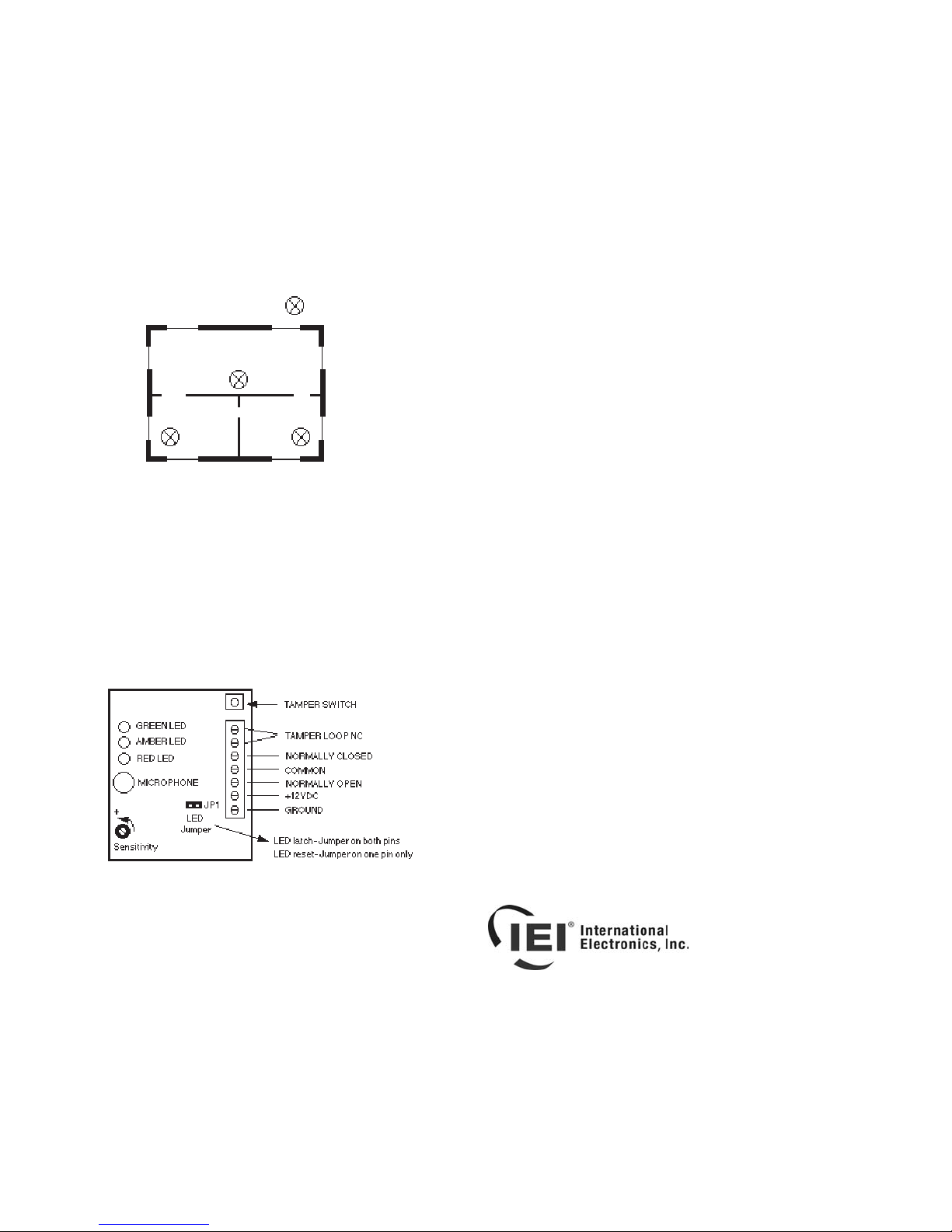
ALARM LED
Auto reset- Remove JP1 jumper from the pins and reinsert on one
pinonly.Onalarm the red alarm LED will light for 3 seconds and reset.
Latch- To latch the red LED in memory leave JP1 on both pins.
Interrupt power for 5 seconds to reset latched LED.
Note: Alarm relay will reset after 3 seconds.
TESTING/SENSITIVITY ADJUSTMENT
The sensitivity is increased by rotating the potentiometer counter-
clockwise.Rotatingthepotentiometerclockwisewilldecreasethesen-
sitivity.
For best results use the IEI-515 glass break simulator and follow the
procedureonitslabel.Thetestergeneratessufficientsignal to set the
sensitivity as low as possible to prevent nuisance alarms but high
enough to detect glass breakage.
NOTE: FINAL TEST WITH THE 515 TESTER MUST BE
PERFORMED WITH THE 510 COVER ON.
NOTE: The placement of objects in the room will vary the acoustics.
Smalldisplacementsof thetester and objectsnear the 510 can make
largedifferencesin the sensitivitysetting. This will appear tomake the
tests inconsistent. Therefore, use this test as a guide for the setting
then take into consideration the environment (hard or soft), the dis-
tancefromthewindowtothedetectorandtheambientnoise(watchfor
the yellow led on the 510- it will light if there is too much background
noise present). If the tester has the 510 sensitivity set very low, for
example, at 30+ foot setting in a living room it is probably a quirk of
acousticsandyoushould set the sensitivity higher. If the yellow led is
on frequently during conditions typical to when the alarm system will
be armed you may need to reposition the detector and/or lower the
sensitivity and add detectors to get the proper coverage.
IEI LimitedWarranty:
Becausethemanufacturerdoesnotinstallor connect this security device the manufacturer
cannot guarantee its performance.Therefore, there are no warranties, expressed or
implied (except as stated below),attached to the sale or use of this product.
The manufacturer warrants against defects in material and workmanship in this device
for3yearsfromthedateofmanufacture.During the warranty period the manufacturer,at
its sole option,will repair or replace free of charge any defective unit returned freight pre-
paid.Thiswarranty shall remain in force and effectfor3yearsprovidedtheunitwasprop-
erlyinstalledand operated,has not been subject to misuse and has not been repairedor
altered other than by the original manufacturer.
The foregoing states the buyer's sole and exclusive remedy for any breach of warranty
or for any claim,whether sounding in contract,tort, strict liability,or negligence,based
upon any defect in this security device.
The manufacturer shall in no event be responsible for any incidental or consequential
damages incurred by the buyer.
This warranty supercedes all previous warranties.
IEI-510 OPTIMUM LOCATIONS
427 TURNPIKE STREET, CANTON, MA 02021 U.S.A.
800-343-9502 OR IN MA 800-733-9502
510 REV. 1.01 615-1000 MADE IN U.S.A.