iENERGY i-Manager User manual
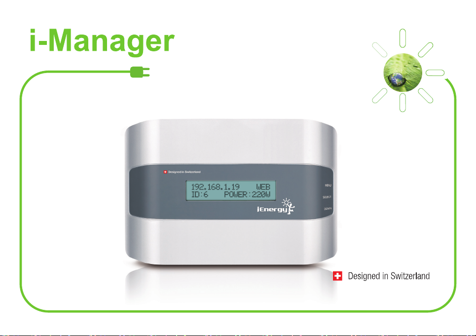
EZ Installation Guide

English
German
Danish
Dutch
French
Spanish
Portuguese
1-8
9-16
17-24
25-32
33-40
41-48
49-56

EZ Installation Guide
Be sure to complete i-Micro inverter installation before using this guide!
i-Manager - Your i-Monitor Solution!
This i-Manager is designed to support the system owner to
easily check the detailed information of how each module is
performing by using power line communication.
This allows the system owner to monitor the status of the PV
performance through the internet at any time and any place.
This EZ installation guide contains important instructions of
the i-Manager. Please read this guide carefully and follow all
instructions to ensure a safe installation and operation.
English
1

Note : Once reset all historical data will be lost.
2

3

1
2
3
Check if all i-Micro inverter GT260 are properly installed and verify the AC solar switch is in “ON”
position in AC load center, and then check that LED indicator on i-Micro inverters shows solid
green LED.
Install an electrical outlet (fixed or floating) on the AC solar switch, and place the i-Manager
so that its AC cord can reach this dedicated outlet directly without any extended line to avoid
possible electrical interference. Please refer to the pictures for Typical Single Phase System
Connection Design and Typical Three Phase System Connection Design in the following page.
Use Ethernet cable to connect i-Manager to Ethernet router.
(Option): In cases where the internet router is located far away from i-Manager, i-Energy provides
i-Bridge accessory which can bridge connection between i-Manager and router by power line
communication to avoid long internet cabling distance. Or alternatively, Powerline Ethernet
Bridges available in electrical retail stores can be used to connect i-Manager to the Ethernet
router without the long Ethernet cabling.
ROW diagram
220V, 50-60Hz
4
4

Typical Single Phase System Connection Design
5

For an example as gure shown, L1 and L2 are close together so it is the perfect condition for the Power Line Communication Cross Phase Coupling
to the L1 and L2 inverters group, but not L3 group. Therefore, it must have inverter group that located under L1 phase and L2 phase to be registered
under the same i-Manager device. And inverter group that located under L3 phase should be registered under another i-Manager device in order to
ensure the Power Line Communication is working steady without any lose.
Typical Three Phase System
Connection Design
For 3-Phase system connection, it is
important to conrm the merge point
for the Power Line Communication
Cross Phase Coupling from the
3-Phase grid system.
6
For more different applications of 3-phase system, please visit http://www.i-energyinc.com/en/products/i-manager.html to download the
i-Manager connection technical brief document for your reference.

Set Up the i-Manager
After plugging in the i-Manager, the screen will
display the IP address as “169.254.0.1” on the
left side of the screen.
The screen will switch from the given IP to
date/time information within 10 seconds.
Within a few seconds, a new IP address is
issued by local router on the i-Manager screen.
Open internet browser and enter the new IP of
the i-Manager in your browser’s address bar.
New
Make sure that the i-Manager plugs directly into the electrical outlet (wall socket) closest to the
AC load center. Do not use power strip or extension cord.
This ensures that i-Manager receives the strongest possible signal from each i-micro inverter.
7

(Optional) If you found your i-Manager device have IP conict with other network device,
conrm the IP address setting information from your local ISP provider and follow the
setup steps below to save the static IP information into i-Manager.
Please skip Step 4 and go to Step 5 directly if you obtain an IP address automatically.
Enter the given IP from i-Manager that issued by your local network device onto your browser:
P.S. If LCD of i-Manager still shows the defaulted IP address of i-Manager (169.254.0.1), please access
to www.i-energyinc.com/en/downloads-support/user-guide-new.html to download "Static IP Local
Setting Mode"document in order to complete a setup for the statics IP firstly before creating your
account and registering i-Micro inverter and i-Manager on the i-Monitor.
i. The i-Manager Device Setup page will be shown and then click “ Network Setup “ to access the
i-Manager Network Setup menu:
8

ii. Select the "Obtain an IP address automatically" option to "NO" and enter the information for the static
IP addresses.
iii. Enter the correct information for the required IP address information to each column.
Ensure all the entered IP address information are correct, any incorrect IP information will let
i-Manager not able to connect with the internet. Therefore, please double conrm the required IP
address information with the ISP provider before entering the IP values.
9

iV. After all IP information is entered correctly, please press the Submit button to save the entered
information to the i-Manager. And then a Data Saved Finished dialogue box will be shown if all
entered IP information is submitted successfully.
V. Find the new static IP address shown on the LCD screen from the i-Manager, and then use this
new IP address as the given IP to access to the i-Manager device setup page.
At the same time, the LCD screen of i-Manager is shown “Save
IP Parameter..” , which means the entered IP information has
been saved into the i-Manager device successfully.
Save IP Parameter..
10

After i-Monitor login dialog box pops up, choose “SIGN UP” to register a new account.
After completing registration form, i-Monitor will ask you to log in using newly created
user name and password. Then proceed to Step 6.
Log in at www.i-energyinc.com
11

Using “System Mapping Guide”, enter i-Micro inverter serial numbers. Use “+” to add
additional i-Micro inverters. Click NEXT when nished.
Using “System Mapping Guide” enter i-Manager serial number and
name i-Manager. Enter address and click submit.
Note: Please wait 10 to 30 minutes for the i-Manager to begin receiving the rst data set from all i-Micro
inverters. Check the screen of i-Manager. When the ID number and power information are shown the
connection has been completed.
Now you can monitor all i-Micro inverters through the i-Monitor system on the internet.
System Mapping Guide
12

Click the address to view your system energy output.
View energy generated from Power
Output page.
Log in to your i-Energy account at www.i-energyinc.com to view your system performance anytime
and anywhere via the internet!
For a complete i-Monitor overview, download the i-Manager user manual at www.i-energyinc.com.
For technical service support or troubleshooting,
please contact your local installer for assistance.
13

Schnellinstallationsleitfaden
Bitte stellen Sie sicher, dass Sie die Micro-inverter-Installation
abgeschlossen haben, bevor Sie mit dieser Anleitung fortfahren!
i-Manager - Ihre i-Monitor-Lösung!
Der i-Manager wurde entwickelt, um den Anlagenbetreiber
bei der Überprüfung der detailierten Informationen über
die erbrachte Leistung jedes einzelnen Moduls durch
Anwendung der Power Line Communication Technologie
zu unterstützen. Dies ermöglicht dem Anlagenbetreiber,
den Status der PV Leistung über das Internet jederzeit und
überall zu überwachen.
Dieser Schnellinstallationsleitfaden enthält wichtige
Anweisungen für den i-Manager. Bitte lesen Sie diese
Anleitung sorgfältig und befolgen sämtliche Anweisungen,
um eine sichere Installation und einen sicheren Betrieb zu
gewährleisten.
German
14

Funktionsübersicht
Taste
Wechseln von der Hauptanzeige zur Menüauswahl.
Auswahl des aktuellen Funktionspunktes des Menüs.
Verschieben des Cursors zwischen den
Funktionspunkten des Menüs.
Zurücksetzen des i-Managers auf
ursprüngliche Werkeinstellungen – Alle Daten
einschließlich IP-Adresse, angeschlossener
i-Micro Inverter und Datums-/
Zeitinformationen werden zurückgesetzt.
Anmerkung: Alle historischen Daten werden beim
Zurücksetzen gelöscht!
Der i-Manager ist für den Temperaturbereich von 0 °C bis 40 °C geprüft und zugelassen.
Wandbefestigungsbuchse
AC Kabelbuchse
RJ45-Ethernet-Buchse
Kabelführungsschlitz
15

Prüfen vor der Inbetriebnahme des i-Managers
16

1
2
5
6
4
3
ROW diagram
220V, 50-60Hz
Überprüfen Sie, ob alle i-Micro inverter GT260 korrekt installiert & in Betrieb genommen worden sind
und stellen Sie sicher, dass der AC-Schutzschalter im AC-Lastschwerpunkt in der “Ein”-Stellung ist.
Überprüfen Sie auch, ob das LED Licht am Micro inverter grün leuchtet.
Lokalisieren Sie eine Steckdose in der Nähe der Strom-Unterverteilung und positionieren Sie den
i-Manager so, dass dessen Netzstecker diese Steckdose erreichen kann.
Stecken Sie den Netzstecker des i-Managers in eine für ihn gewidmete Steckdose, um mögliche
elektrische Störungen durch andere Haushaltsgeräte zu vermeiden.
Für das beste Resultat, ziehen Sie alle anderen Geräte ab, die sich den Auslass mit dem i-Manager
teilen könnten.
Verwenden Sie das Ethernetkabel, um den i-Manager mit dem Ethernet Router zu verbinden.
(i-Bridge Option): Falls Ihr Internetrouter zu weit entfernt vom i-Manager positioniert ist, bietet der
i-Bridge eine Brückenverbindung für lange Distanzen zwischen dem i-Manager und dem Router über
Power Line Communication.
17

Schritte zur Inbetriebnahme des i-Managers
New
Schritt 1
Schritt 2
Schritt 3
Nach dem Einstecken des i-Managers in die
Steckdose wird die IP-Adresse „169.254.0.1“ am
linken Bildschirmrand angezeigt.
Die Anzeige wechselt alle 10 Sekunden von der
vorgebenen IP-Adresse zur Datums-/Zeitinformation.
Innerhalb weniger Sekunden erscheint eine neue IP-
Adresse am Bildschirm, die von Ihrem lokalen Router
vergeben wird.
Öffnen Sie den Webbrowser und geben Sie die
vorgegebene IP-Adresse des i-Managers in die
Adressleiste Ihres Webbrowsers am Computer ein.
WICHTIG:
Vergewissern Sie sich, dass der i-Manager in die Steckdose gesteckt wird, die sich am nähesten
zum Sicherungskasten bendet. Dies soll sicherstellen, dass der i-Manager das stärkstmögliche
Signal von jedem Micro inverter empfängt.
18
Table of contents
Languages:
Other iENERGY Inverter manuals
Popular Inverter manuals by other brands

Soluciones Electronicas
Soluciones Electronicas SOLENER user manual

Wacker Neuson
Wacker Neuson GV 7000A Operator's manual

C.E. Nierhoff & Co
C.E. Nierhoff & Co C528 troubleshooting guide

Sungrow
Sungrow SG320HX user manual

Steamist
Steamist HC-9 owner's manual

Evenlite
Evenlite EMS Series Installation and operation instruction

Xantrex
Xantrex PV-15208 Operation and maintenance manual

Huayu
Huayu HY-MDL Installation and operation manual

Siemens
Siemens MICROMASTER 430 operating instructions

enphase
enphase M250 Quick install guide

ulsonix
ulsonix AIRCLEAN 10G-WM2 user manual

Solectria Renewables
Solectria Renewables STRCOM 10X A Series Installation and operation manual