10
www.max.us.com
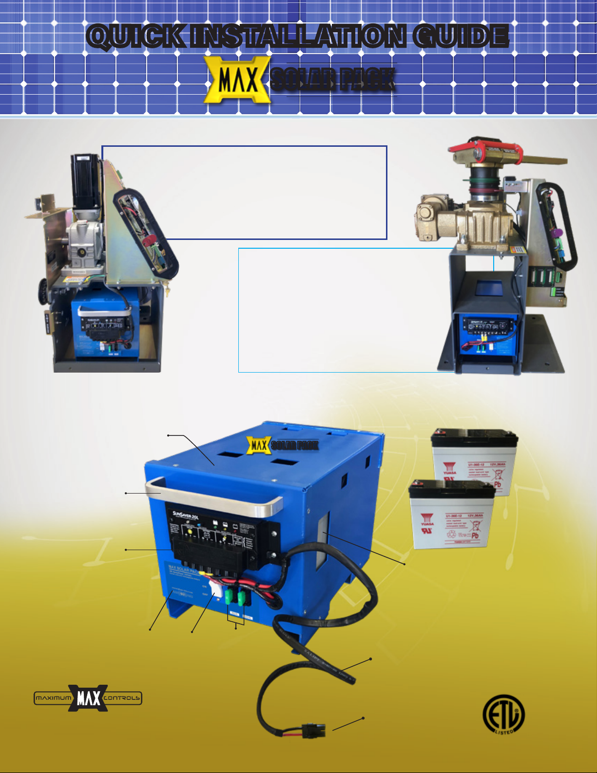
QUICK INSTALLATION GUIDE
MAX SOLAR PACK
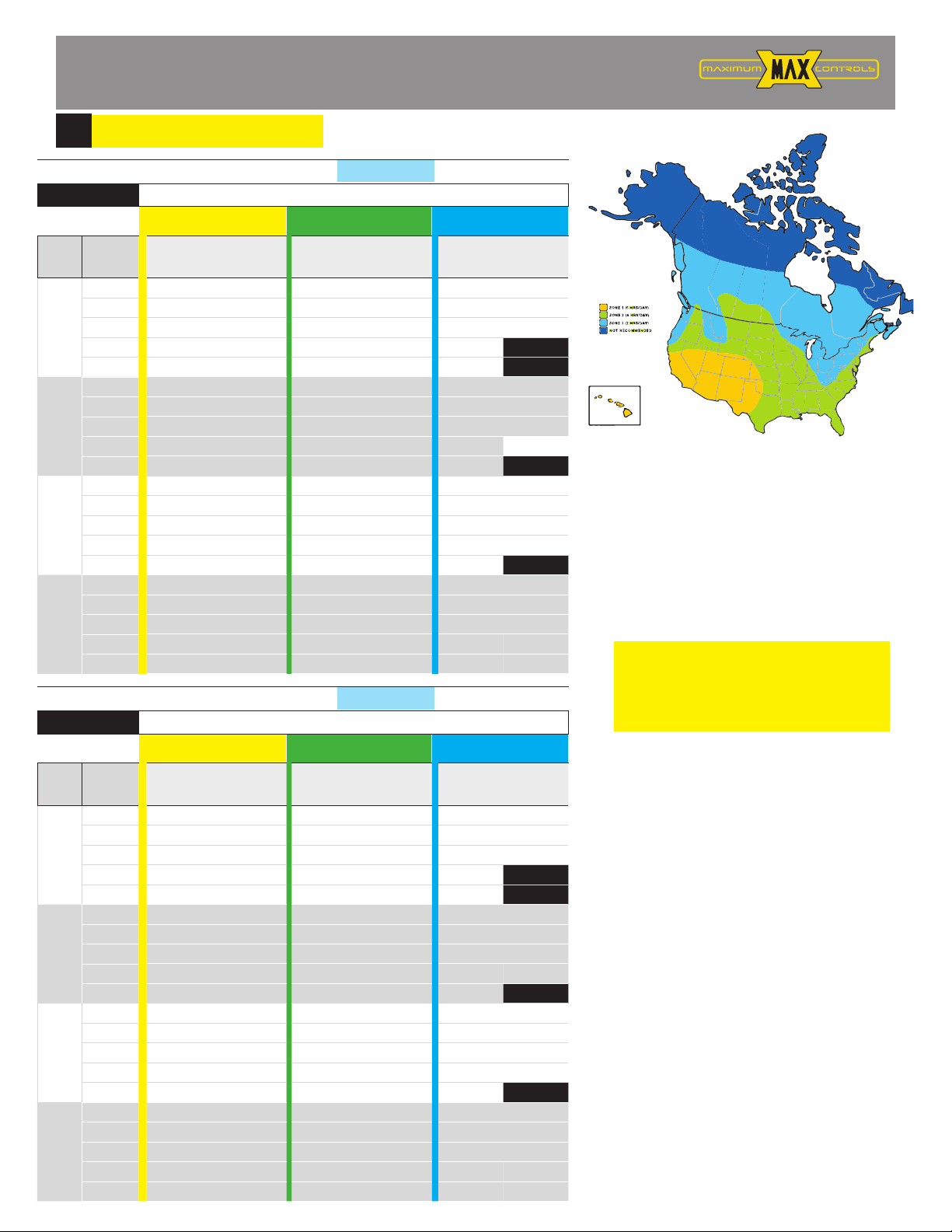
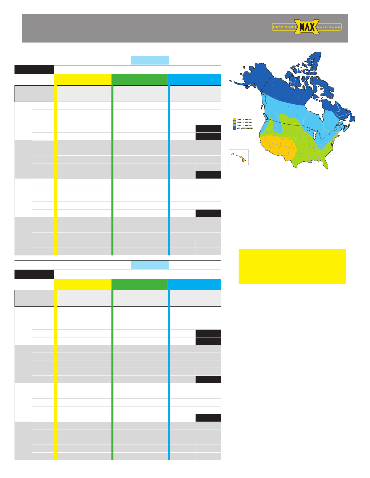
Select proper solar panel and batter
1
The map and daily cycle rate shown are
approximations based upon the average
solar radiation and the temperature
effects on batteries in the given regions.
Local geography and weather conditions
may require additional solar panels.
USE LOW POWER accessories in order to
minimize power draw. Each additional
accessory draws power affecting the daily
cycle rate.
SWING, PAD MOUNT, LIGHT GATE
MEGATRON PRO GATE SOLAR CYCLES PER DAY with built-in 36A/Hr battery
ZONE 1
(6 Hrs Sunlight/Day)
ZONE 2
(4 Hrs Sunlight/Day)
ZONE 3
(2 Hrs Sunlight/Day)
PANEL SIZE
Total System
Current
Draw (mA)
Cycles/day
w/1
rainy day
Cycles/day
w/10
rainy days
Cycles/day
w/1
rainy day
Cycles/day
w/10
rainy days
Cycles/day
w/1
rainy day
Cycles/day
w/10
rainy days
60 W
26 726 137 697 108 669 80
50 716 127 686 97 657 68
100 695 106 664 75 632 43
200 655 65 618 29 582 -7
250 634 45 595 6 557 -32
85 W
26 760 171 720 131 680 91
50 750 161 709 120 668 79
100 730 140 686 97 643 54
200 689 100 641 52 593 4
250 668 79 618 29 568 -21
120 W
26 808 218 752 163 696 107
50 798 209 741 152 684 95
100 777 188 718 129 659 70
200 736 147 673 84 609 20
250 716 127 650 61 584 -5
200 W
26 917 328 825 235 732 143
50 907 318 814 225 720 131
100 886 297 791 202 695 106
200 845 256 745 156 645 56
250 825 236 723 134 620 31
SWING, PAD MOUNT, HEAVY GATE
MEGATRON PRO GATE SOLAR CYCLES PER DAY with built-in 36A/Hr battery
ZONE 1
(6 Hrs Sunlight/Day)
ZONE 2
(4 Hrs Sunlight/Day)
ZONE 3
(2 Hrs Sunlight/Day)
PANEL SIZE
Total System
Current
Draw (mA)
Cycles/day
w/1
rainy day
Cycles/day
w/10
rainy days
Cycles/day
w/1
rainy day
Cycles/day
w/10
rainy days
Cycles/day
w/1
rainy day
Cycles/day
w/10
rainy days
60 W
26 454 85 436 68 418 50
50 447 79 429 61 411 42
100 435 66 415 47 395 27
200 409 41 386 18 364 -5
250 396 28 372 4348 -20
85 W
26 475 107 450 82 425 57
50 469 101 443 75 418 49
100 456 88 429 61 402 34
200 430 62 401 32 371 3
250 418 49 386 18 355 -13
120 W
26 505 137 470 102 435 67
50 499 130 463 95 428 59
100 486 118 449 81 412 44
200 460 92 420 52 381 13
250 447 79 406 38 365 -3
200 W
26 573 205 515 147 458 90
50 567 199 509 140 450 82
100 554 186 494 126 435 66
200 528 160 466 98 403 35
250 516 147 452 84 388 20