IES Keywatt 19 User manual
User Manual
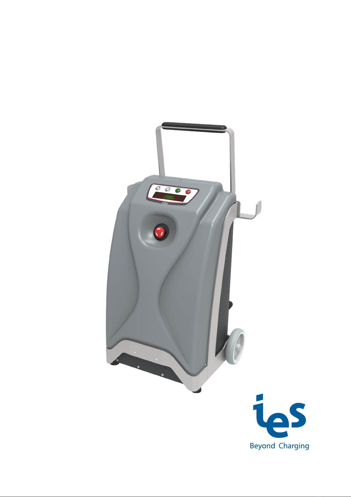
Keywatt 19 Trolley
www.ies-synergy.com
DUM016199-EN_V002b

www.ies-synergy.com
User Manual DIM016199-EN
2
The information provided in this documentation contains general descriptions and/or technical characteristics
of the performance of the products contained herein. This documentation is not intended as a substitute for
and is not to be used for determining suitability or reliability of these products for specific user applications. It
is the duty of any such user or integrator to perform the appropriate and complete risk analysis, evaluation and
testing of the products with respect to the relevant specific application or use thereof. Neither IES Synergy nor
any of its affiliates or subsidiaries shall be responsible or liable for misuse of the information contained herein.
If you have any suggestions for improvements or amendments or have found errors in this publication, please
notify us.
You agree not to reproduce, other than for your own personal, noncommercial use, all or part of this document
on any medium whatsoever without permission of IES Synergy, given in writing. You also agree not to establish
any hypertext links to this document or its content. IES Synergy does not grant any right or license for the per-
sonal and noncommercial use of the document or its content, except for a non-exclusive license to consult it on
an “as is” basis, at your own risk. All other rights are reserved.
All pertinent state, regional, and local safety regulations must be observed when installing and using this prod-
uct. For reasons of safety and to help ensure compliance with documented system data, only the manufacturer
should perform repairs to components.
When devices are used for applications with technical safety requirements, the relevant instructions must be
followed.
Failure to use IES Synergy software or approved software with our hardware products may result in injury,
harm, or improper operating results.
Failure to observe this information can result in injury or equipment damage.
© 2020 IES Synergy. All rights reserved.

www.ies-synergy.com
User Manual DIM016199-EN
3
Table of content
1. Safety notes 4
Notice 4
Please note 4
2. About the manual 5
Purpose of this manual 5
Document scope 5
Related documents 5
User comments 5
3. General Safety instructions 6
4. Overview 7
External view 7
Internal door view 8
5. Specification 9
Technical specification 9
Compliance 11
6. Handling and storage instructions 12
Storage 12
Transport 12
7. Installation 13
Visual inspection 13
Installation rules 13
Plug connections 14
AC input connector 14
DC output connector 15
8. Charger operation 16
Front panel 16
Rear Panel 16
Starting up 17
Charge with COMBO 1 or COMBO 2 connector 19
Charge with CHADEMO connector 23
Charge with GB connector 26
Charge error messages 29
Emergency Stop messages 29
List of error messages 30
9. Cleaning 32
10. Protecting the environment 33
Recycling Packaging 33
End-of-Life Recycling 33
www.ies-synergy.com
User Manual DIM016199-EN
4
1. Safety notes
Notice
Read these instructions carefully, and look at the equipment to become familiar with the device before trying
to install, operate, or maintain it. The following special messages may appear throughout this documentation
or on the equipment to warn of potential hazards or to call attention to information that clarifies or simplifies
a procedure.
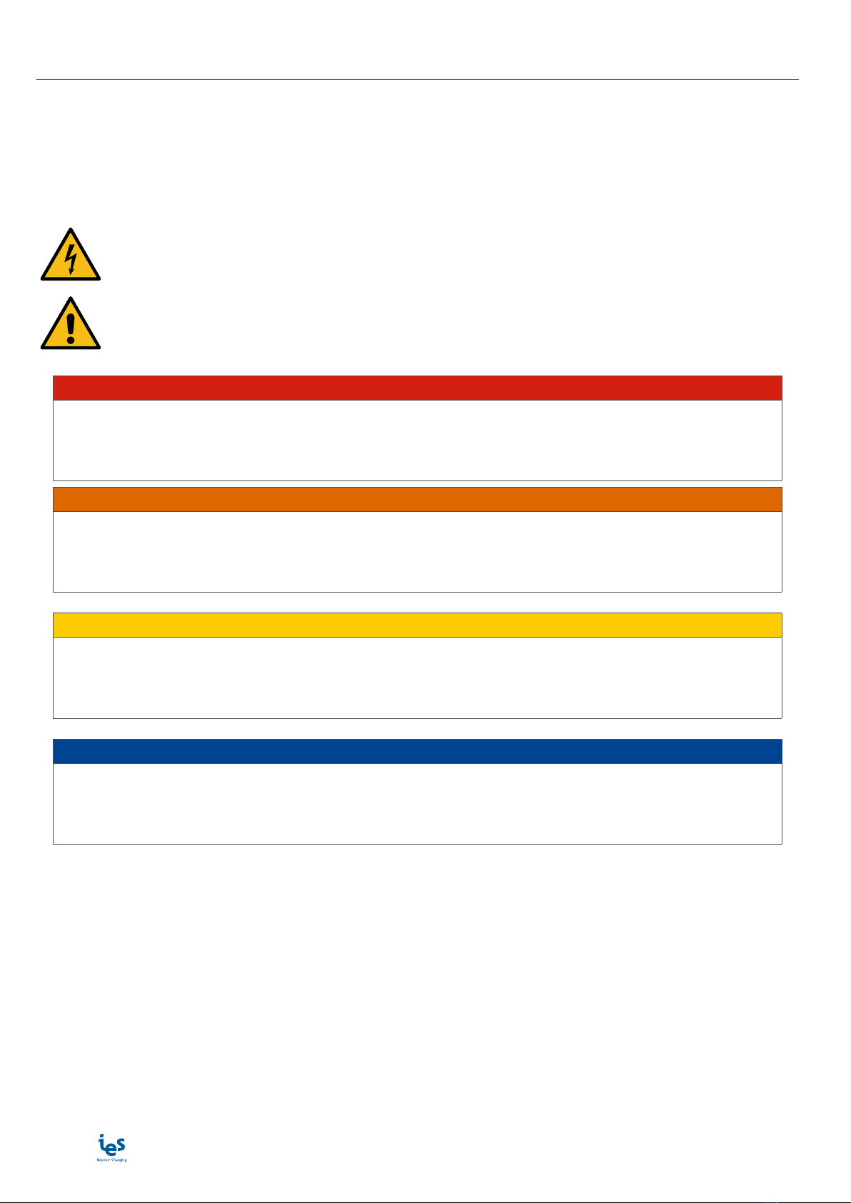
The addition of this symbol to a Danger hazard statements indicates that an electrical hazard
exists, wich result in personal injury if the instructions are not followed.
This is the safety alert symbol. It is used to alert you to potential personnal injury hazards. Obey
all safety messages that follow this symbol to avoid possible injury or death.
IDANGER
DANGER indicates an imminently hazardous situation which, if not avoided, will result in death or seri-
ous injury.
IWARNING
WARNING indicates a potentially hazardous situation which, if not avoided, can result in death or seri-
ous injury.
ICAUTION
CAUTION indicates a potentially hazardous situation which, if not avoided, can result in minor or mod-
erate injury.
NOTICE
NOTICE is used to address practices not related to physical injury.
Please note
Electrical equipment should be installed, operated, serviced, and maintained only by qualified personnel. No
responsibility is assumed by IES Synergy for any consequences arising out of the use of this material.
A qualified person is one who has skills and knowledge related to the construction and operation of electrical
equipment and its installation, and has received safety training to recognize and avoid the hazards involved.
www.ies-synergy.com
User Manual DIM016199-EN
5
2. About the manual
Purpose of this manual
Technical documentation is an integral part of a product. Until it is disposed of, always keep the technical docu-
mentation close to the unit at hand, as it contains important information. Provide technical documentation to
the person concerned if you sell, assign or lend the product.
This guide aims to provide informations needed for installation, use and end-of life of the charger Keywatt 19
Trolley. This guide must be read in integrality with others related documents. This guide is intended for users
of the charging station.
Document scope
This guide concerns the following charging station :
• Art/N : TROLLEY 19KW DC CHARGER
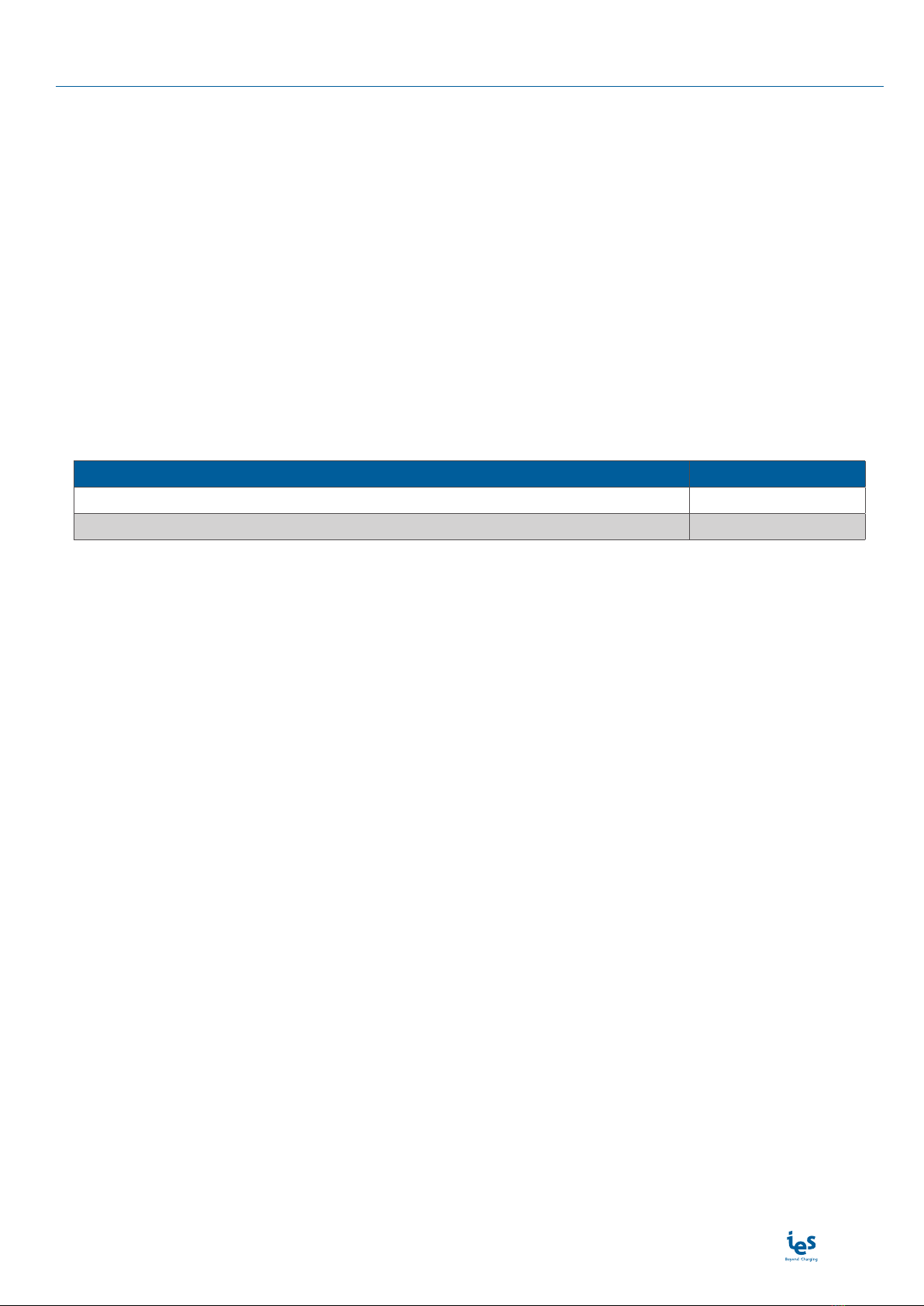
Related documents
Document title Reference
User Manual DUM016199-EN
Service Manual
User comments
We invite you to write us to communicate any inaccuracies or omissions, or to make general comments or sug-
gestions regarding the quality of this manual.
Table of contents
Popular Outdoor Cart manuals by other brands


Carts Vermont
Carts Vermont 20 manual

Westward
Westward 2CZY4 Operating instructions and parts manual

Numatic
Numatic EcoMatic EM-5 Assembly

Bosch
Bosch XL-Cart Operating/safety instructions

Tennsco
Tennsco Modular Cart Top Component Assembly Assembly Instructions/Parts Manual

Clam
Clam POLAR TRAILER HD MAX manual


