IET Labs, Inc. RLC Digibridge 1693 Troubleshooting guide

♦ PRECISION INSTRUMENTS FOR TEST AND MEASUREMENT ♦
TEL: (516) 334-5959 • (800) 899-8438 • FAX: (516) 334-5988
www.ietlabs.com
534 Main Street, Westbury, NY 11590
IET LABS, INC.
Copyright © 2012 IET Labs, Inc.
Visit www.ietlabs.com for manual revision updates
1693 im/September 2012
1693
RLC Digibridge
User and Service Manual

TEL: (516) 334-5959 • (800) 899-8438 • FAX: (516) 334-5988
534 Main Street, Westbury, NY 11590
IET LABS, INC.
www.ietlabs.com
Standards • Decades • Strobes • Sound Level Meters • Bridges

TEL: (516) 334-5959 • (800) 899-8438 • FAX: (516) 334-5988
534 Main Street, Westbury, NY 11590
IET LABS, INC.
www.ietlabs.com
Standards • Decades • Strobes • Sound Level Meters • Bridges
i
1693 RLC Digibridge
WARRANTY
We warrant that this product is free from defects in material and workmanship and, when properly used,
will perform in accordance with applicable IET speci cations. If within one year after original shipment,
it is found not to meet this standard, it will be repaired or, at the option of IET, replaced at no charge when
returned to IET. Changes in this product not approved by IET or application of voltages or currents greater
than those allowed by the speci cations shall void this warranty. IET shall not be liable for any indirect,
special, or consequential damages, even if notice has been given to the possibility of such damages.
THIS WARRANTY IS IN LIEU OF ALL OTHER WARRANTIES, EXPRESSED OR IMPLIED,
INCLUDING BUT NOT LIMITED TO, ANY IMPLIED WARRANTY OF MERCHANTABILITY OR
FITNESS FOR ANY PARTICULAR PURPOSE.

ii
1693 RLC Digibridge
WARNING
OBSERVE ALL SAFETY RULES
WHEN WORKING WITH HIGH VOLTAGES OR LINE VOLTAGES.
Dangerous voltages may be present inside this instrument. Do not open the case
Refer servicing to quali ed personnel
HIGH VOLTAGES MAY BE PRESENT AT THE TERMINALS OF THIS INSTRUMENT
WHENEVER HAZARDOUS VOLTAGES (> 45 V) ARE USED, TAKE ALL MEASURES TO
AVOID ACCIDENTAL CONTACT WITH ANY LIVE COMPONENTS.
USE MAXIMUM INSULATION AND MINIMIZE THE USE OF BARE
CONDUCTORS WHEN USING THIS INSTRUMENT.
Use extreme caution when working with bare conductors or bus bars.
WHEN WORKING WITH HIGH VOLTAGES, POST WARNING SIGNS AND
KEEP UNREQUIRED PERSONNEL SAFELY AWAY.
CAUTION
DO NOT APPLY ANY VOLTAGES OR CURRENTS TO THE TERMINALS OF THIS
INSTRUMENT IN EXCESS OF THE MAXIMUM LIMITS INDICATED ON
THE FRONT PANEL OR THE OPERATING GUIDE LABEL.

iiiTable of Contents
1693 RLC Digibridge
Table of Contents
Safety Information
General safety information .................................................................................................................. xi
Abbreviated Specifications
Features ................................................................................................................................................ xiii
Applications ......................................................................................................................................... xiii
Specications ....................................................................................................................................... xiii
Condensed operating instructions ........................................................................................................ xx
Chapter 1 Introduction
1.1 Purpose ....................................................................................................................................... 1
1.2 General Description .................................................................................................................... 2
1.2.1 1693 RLC Digibridge Overview ...................................................................................... 2
1.2.2 References ........................................................................................................................ 2
1.3 Controls, Indicators, and Connectors ......................................................................................... 2
1.4 Accessories ................................................................................................................................. 6
1.4.1 Supplied accessories ......................................................................................................... 6
1.4.2 Optional Accessories ........................................................................................................ 6
Chapter 2 Installation
2.1 Unpacking and Inspection .......................................................................................................... 8
2.2 Dimensions ................................................................................................................................. 8
2.3 Power Line Connection .............................................................................................................. 8
2.4 Line-Voltage Regulation ............................................................................................................. 8
2.5 Test-Fixture Connections ............................................................................................................ 9
2.6 Bias Voltage for the DUT ........................................................................................................... 9
2.6.1 Internal Bias ..................................................................................................................... 9
2.6.2 External Bias .................................................................................................................... 9
2.7 IEEE-488 Interface ..................................................................................................................... 10
2.7.1 Description ....................................................................................................................... 10
2.7.2 Signal Identication ......................................................................................................... 10
2.7.3 Codes and addresses ......................................................................................................... 10
2.8 Environment ............................................................................................................................... 12
2.9 Rack Mount Option .................................................................................................................... 12

iv Table of Contents
1693 RLC Digibridge
Chapter 3 Operation
3.1 Basic Operation .......................................................................................................................... 13
3.1.1 Overview .......................................................................................................................... 13
3.1.2 Startup .............................................................................................................................. 13
3.1.3 Zeroing ............................................................................................................................. 14
3.1.4 Routine Measurement....................................................................................................... 17
3.2 Connecting the DUT ................................................................................................................... 18
3.2.1 Overview .......................................................................................................................... 18
3.2.2 The 1689-9600 Remote Test Fixture (with 1689-9602 BNC Cable) ............................... 18
3.2.3 Using the Test-Fixture Adaptors for Axial-Lead DUT ..................................................... 19
3.2.4 1657-9600 Banana Plug Extender Cable.......................................................................... 20
3.2.5 The 1689-9602 Extender Cable with bnc-to-Banana-Plug Adaptors ............................... 21
3.2.6 The Effects of Cable and Fixture Capacitances ............................................................... 21
3.2.7 7000-05 Tweezers ............................................................................................................. 22
3.2.8 1700-03 Kelvin Clip Cable............................................................................................... 23
3.2.9 7000-04 Alligator Clip Leads ........................................................................................... 24
3.2.10 Connection to HACS-Z High Accuracy Decade Capacitor ........................................... 25
3.2.11 Connection to 1482 Inductance Standard ....................................................................... 27
3.2.12 Connection to 1409 Capacitance Standards ................................................................... 28
3.2.13 Connection to 1404 Reference Standard Capacitor ....................................................... 29
3.2.14 Connection to 1417 Capacitance Standard ..................................................................... 30
3.2.15 Connection to the 1433 Decade Resistor ....................................................................... 31
3.3 Measurement Parameters, Result Displays, and Outputs ........................................................... 33
3.3.1 Parameters (R/Q,L/Q,
C/D,C/R,R/X,G/B,Z/ANG,Y/ANG) ............................................................................................ 33
3.3.2 Equivalent Circuits - Series, Parallel ................................................................................ 34
3.3.3 Results Displayed ............................................................................................................. 37
3.3.4 Units, Multipliers, and Blank Displays ............................................................................ 39
3.3.5 D, Q, ANG in PPM ........................................................................................................... 40
3.3.6 Ratio Displays, Virtual Range Extensions, and Conductance Measurements.................. 41
3.4 Principal Test Conditions ............................................................................................................ 42
3.4.1 Test Frequency.................................................................................................................. 42
3.4.2 Test Voltage ...................................................................................................................... 43
3.4.3 Constant Voltage Source................................................................................................... 44
3.4.4 Constant Current Source .................................................................................................. 44
3.4.5 Other Conditions .............................................................................................................. 44

v
1693 RLC Digibridge
3.5 Measurement Time and Measurement Ranges ........................................................................... 45
3.5.1 General ............................................................................................................................. 45
3.5.2 Measure Rate Selection at Keyboard ............................................................................... 45
3.5.3 Settling Time or Programmed Delay, in Triggered Measure Mode ................................. 46
3.5.4 Measure Mode and Display Selection, Effects on Measurement Time ........................... 46
3.5.5 Integration-Time Factor (a Special Function) .................................................................. 46
3.5.6 Ranges and Range Changing ............................................................................................ 47
3.5.7 Range Holding .................................................................................................................. 48
3.5.8 Time Required for Obtaining Median Values and Averaging .......................................... 49
3.5.9 Time Required if IEEE-488 Output is Enabled ................................................................ 50
3.5.10 Effect of Selecting a Low Test Frequency on Measurement Time................................. 50
3.5.11 Measurement Time Summary......................................................................................... 51
3.6 Accuracy, The Limits of Errors .................................................................................................. 52
3.6.1 General ............................................................................................................................. 52
3.6.2 Accuracy for Some Typical Conditions ............................................................................ 53
3.6.3 Averaging to Improve Accuracy ....................................................................................... 54
3.6.4 Selection of Median Value for Better Accuracy ............................................................... 55
3.6.5 Accuracy Enhancement for Large or Small Impedances at Particular Frequencies ......... 55
3.6.6 Accuracy Enhancement by Special Attention to Short-Circuit Inductance ...................... 56
3.6.7 Cable-Related Errors and How to Correct for them ......................................................... 57
3.6.8 Use of Signal Reversing (Special Function) for Tests at Power Frequencies .................. 58
3.6.9 Accuracy When Holding a Non-Optimum Range ............................................................ 59
3.7 Bias for the DUT ........................................................................................................................ 59
3.7.1 Internal Bias ..................................................................................................................... 59
3.7.2 External Bias .................................................................................................................... 60
3.7.3 Suppression or Transients ................................................................................................. 62
3.8 Bin Sorting and Go/No-Go Results ............................................................................................ 62
3.8.1 Introduction to Binning (Sorting Based on Limit Comparisons) ..................................... 62
3.8.2 Sorting Methods ............................................................................................................... 62
3.8.3 Limit Entry Procedure ...................................................................................................... 63
3.8.4 Verication of Nominal and Limit Values ........................................................................ 64
3.8.5 Examples of Limit Entry .................................................................................................. 65
3.8.6 Notes on Limit Entries in General .................................................................................... 66
3.8.7 Go/No-Go and Bin Assignment Results ........................................................................... 67
3.8.8 Bin Sum Information ........................................................................................................ 67
3.8.9 Binning and Ratio Measurement Simultaneously ............................................................ 67

vi Table of Contents
1693 RLC Digibridge
3.9 Keyboard Lock, Function Map, and Summary of Integrations .................................................. 69
3.9.1 Keyboard Lock ................................................................................................................. 69
3.9.2 Function Map ................................................................................................................... 69
3.9.3 Summary of Interrogations ............................................................................................... 70
3.10 Special Functions ...................................................................................................................... 71
3.11 Data Output and Programming via IEEE 488 and RS-232 Interface ....................................... 72
3.11.1 Overview ........................................................................................................................ 72
3.11.2 Conguration .................................................................................................................. 72
3.11.3 Talk-Listen / Talk-Only Toggle Switch .......................................................................... 72
3.11.4 GPIB Address DIP Switch .............................................................................................. 73
3.11.5 Jumpers ........................................................................................................................... 73
3.11.6 RS-232 Serial Interface (Currently Not Implemented) .................................................. 73
3.11.7 Instrument Program Commands ..................................................................................... 74
3.11.8 Legacy Digibridge IEEE-488 Commands ...................................................................... 75
3.11.9 IEEE 488.2/SCPI Digibridge Command Summary ....................................................... 77
3.11.10 IEEE 488.2 / SCPI Digibridge Command Reference ................................................... 80
3.11.11 Example Programming ................................................................................................. 91
3.11.12 Talk-Only Use, for Data Output ................................................................................... 91
3.11.13 Talk/Listen Use, for Remote Programming and Data Transfers .................................. 94
3.11.14 Data Output in Compacted Binary Format ................................................................... 97
3.12 Sample IEEE Programs ............................................................................................................ 100
3.12.1 Programming Hints ........................................................................................................ 100
3.12.2 National Instruments GPIB-PCll Card With the PC ...................................................... 100
3.13 Self-checks and Failure Displays (Error codes) ....................................................................... 101
3.13.1 Power-up Self-Check ..................................................................................................... 101
3.13.2 Failure Display due to Signal Overload ......................................................................... 102
3.13.3 Failure Display due to Abnormal Measurement Cycle .................................................. 102
3.13.4 Failure Display due to LC Resonance ............................................................................ 102
Chapter 4 Theory
4.1 Introduction ................................................................................................................................ 104
4.1.1 General ............................................................................................................................. 104
4.1.2 Brief Description of the 1693 Digibridge......................................................................... 104
4.1.3 Block Diagram ................................................................................................................. 105
4.2 Principal Functions ..................................................................................................................... 107
4.2.1 Elementary Measurement Circuit ..................................................................................... 107
4.2.2 Frequency and Time Source ............................................................................................. 107

viiTable of Contents
1693 RLC Digibridge
4.2.3 Sine-Wave Generation ...................................................................................................... 107
4.2.4 The Dual-Slope Integrating Detector and Converter ....................................................... 109
Chapter 5 Service and Maintenance
5.1 Safety .......................................................................................................................................... 110
5.2 Customer Service ........................................................................................................................ 111
5.3 Instrument Return ....................................................................................................................... 111
5.3.1 Packaging ......................................................................................................................... 111
5.3.2 Repair and Replacement of Circuit Boards ...................................................................... 111
5.4 Performance Verication ............................................................................................................ 112
5.4.1 Overview .......................................................................................................................... 112
5.4.2 Performance Verication Procedure ................................................................................. 112
5.4.3 Measurement-Time Checkout .......................................................................................... 115
5.5 Disassembly and Access ............................................................................................................. 116
5.5.1 Relocation of bnc Connector Bracket .............................................................................. 119
5.5.2 Major internal components ............................................................................................... 120
5.5.3 Interface Options .............................................................................................................. 121
5.5.4 Removal of Multiple-Pin Packages .................................................................................. 122
5.6 Periodic Maintenance ................................................................................................................. 122
5.6.1 Care of Test Fixtures ........................................................................................................ 122
5.6.2 Care of the Display Panel ................................................................................................. 122
5.7 Trouble Analysis ......................................................................................................................... 123
5.7.1 Overview .......................................................................................................................... 123
5.7.2 Power-Up Self check and Certain Aborted Measurements .............................................. 124
5.7.3 Internal Fuse Replacement ............................................................................................... 127
5.7.4 Power Supply and Regulator Board ................................................................................. 128
5.7.5 Sinewave Generator Checks ............................................................................................. 129
5.7.6 Front End Ampliers and Switches .................................................................................. 129
5.8 Accuracy Verication ................................................................................................................. 130
5.8.1 General ............................................................................................................................. 130
5.8.2 Capacitance Measurement Accuracy (Ranges 1-3) .......................................................... 131
5.8.3 Capacitance Measurement Accuracy................................................................................ 132
5.8.4 Resistance Measurement Accuracy .................................................................................. 134
5.8.5 Inductance Measurement Accuracy.................................................................................. 135
5.8.6 D Measurement Accuracy ................................................................................................ 137
5.8.7 Limit Comparison Bins .................................................................................................... 138

viii Table of Contents
1693 RLC Digibridge
Figures and Tables
Figure-A: Source Impedance Factors .........................................................................................................xv
Figure 1-1: 1693 RLC Digibridge, front view ...........................................................................................2
Figure 1-2: 1693 Front Display.................................................................................................................3
Figure 1-3: 1693 Keyboard .......................................................................................................................3
Figure 1-4: Rear controls and connectors on 1693 Digibridge ................................................................5
Figure 1-5: Typical operating guide attached to 1693 ..............................................................................7
Figure 2-1: Input power module with a drawer for the input fuse ............................................................8
Figure 2-2: IEEE-488 interface .................................................................................................................10
Figure 2-3: DIP switch set to Decimal Address 3 .....................................................................................11
Figure 3-1: Open and short measurements with banana plugs .................................................................14
Figure 3-2: Open and short measurements with Kelvin cables .................................................................15
Figure 3-3: Open and short measurements with bnc-to-bnc cables ..........................................................15
Figure 3-4: Open and short measurements with GR874 connectors.........................................................16
Figure 3-5: Chip component tweezers .......................................................................................................16
Figure 3-6: Open and short measurements in 1689-9600 .........................................................................17
Figure 3-7: Connecting remote test xture to RLC Digibrige ...................................................................18
Figure 3-8: 1689-9600 Remote Test Fixture ..............................................................................................19
Figure 3-9: 1689-9600 Remote Test Fixture with 1657-5995 Test Clips ...................................................19
Figure 3-10: Banana plugs on the 1657-9600 cable .................................................................................20
Figure 3-11: Connecting remote test xture and the Extender cable to RLC Digibrige ...........................20
Figure 3-12: 1689-9602 Extender Cable with bnc-to-banana-plug adapters ...........................................21
Figure 3-13: 7000-05 Chip Component Tweezers .....................................................................................22
Figure 3-14: 1700-03 Kelvin Cables .........................................................................................................23
Figure 3-15: 7000-04 Alligator Clip Leads ...............................................................................................24
Figure 3-16: Connecting alligator clips ...................................................................................................24
Figure 3-17: Connection to HACS-Z BP terminals with 1689-9602 cable and 1894 & 4684 adapters ...25
Figure 3-18: Connection to HACS-Z BP terminals with 1657-9600 Extender Cable
or 7000-04 cable (without alligator clips) ..........................................................................................25
Figure 3-19: Connection to HACS-Z bnc terminals with 1689-9602 cable with 6700 adapters ..............26
Figure 3-20: Connecting 1693 to 6-terminal 1482 ...................................................................................27
Figure 3-21: Direct connection of 1693 and 1482 ....................................................................................27
Figure 3-22: Connecting 1693 to a 3-terminal 1482 ................................................................................28
Figure 3-23: Connection to 1409 Standard Capacitor ..............................................................................28
Figure 3-24: Connecting 1693 to a 1404 ..................................................................................................29
Figure 3-25: Connecting to a 1417 ...........................................................................................................30
5.9 Recalibration ............................................................................................................................... 140
5.9.1 Preparation........................................................................................................................ 140
5.9.2 Zeroing and Selecting “DQ in PPM” ............................................................................... 141
5.9.3 Recalibration for Range 4................................................................................................. 141
5.9.4 Recalibration for Range 3................................................................................................. 142
5.9.5 Recalibration for Range 2................................................................................................. 142
5.9.6 Recalibration for Range 1................................................................................................. 143
5.9.7 Frequency Calibration ...................................................................................................... 143
5.9.8 Frequency Correction K Factor Procedure ....................................................................... 144
5.10 Internal Address Settings for IEEE-488 Interface .................................................................... 146

ixTable of Contents
1693 RLC Digibridge
Figure 3-26: Connection to 1433 via 7000-04 cable.................................................................................31
Figure 3-27: Connection to 1433 via 1657-9600 cable.............................................................................32
Figure 3-28: Phase relationships ..............................................................................................................37
Figure 3-29: Relationships of Measurement Time .....................................................................................51
Figure 3-30: General view of the tradeoffs between measurement time and accuracy ............................53
Figure 3-31: Approximate RLC Accuracy vs Test Frequency ....................................................................54
Figure 3-32: Recommended Wire Shapes for Zeroing ...............................................................................56
Figure 3-33: Nested limits for sorting .......................................................................................................63
Figure 3-34: Sequential limits for sorting .................................................................................................63
Figure 3-35: Keyboard Map ......................................................................................................................69
Figure 4-1: Block diagram of the 1693 RLC Digibridge ..........................................................................106
Figure 4-2: Elementary Measurement Circuit ...........................................................................................108
Figure 4-3: Frequency and timing source .................................................................................................108
Figure 4-4: Sine wave generator ...............................................................................................................108
Figure 5-1: Screws holding the interface assembly on the rear panel ......................................................117
Figure 5-2: Interior top view of 1693 Digibridge .....................................................................................118
Figure 5-3: Analog and Control Board Assembly (1689-4702) ................................................................120
Figure 5-4: Display Board Assembly (1689-4705) ....................................................................................120
Figure 5-5: Keyboard Assembly (1687-4200) ...........................................................................................121
Figure 5-6: Power Supply Assembly (700011) ..........................................................................................121
Figure 5-7: IEEE interface (1689-9640), front view .................................................................................121
Figure 5-8: IEEE interface (1689-9640), top view ....................................................................................121
Figure 5-9: Screws holding the interface assembly on the rear panel ......................................................122
Figure 5-10: Timing diagram of the power-up self check. ........................................................................124
Figure 5-11: Location of internal fuse .......................................................................................................127
Figure 5-12: Power Supply and Regulator Board Test Points ..................................................................128
Figure 5-13: Series connections of standards for D accuracy checks ......................................................137
Figure 5-14: Calculating the K factor .......................................................................................................145
Figure 5-15: IEEE-488 interface on the rear panel ..................................................................................146

x Table of Contents
1693 RLC Digibridge
This page is intentionally left blank.

xi
1693 RLC Digibridge
Safety Information
General safety information
Safety Summary
The following general safety precautions must be
observed during all phases of operation, service
and repair of this instrument. Failure to comply
with these precautions or specic WARNINGS
given elsewhere in this manual will violate safety
standards of the design, manufacturing, and
intended use of the instrument. IET Labs. assumes
no liability for the customer’s failure to comply with
these requirements.
Before Applying Power
Verify that the power is set to match the rated input
of this instrument.
Protective Ground
Make sure to connect the protective ground to
prevent an electric shock before turning on the
power.
Necessity of Protective Grounding
Never cut off the internal or external protective
ground wire, or disconnect the wiring of the
protective grounding terminal. Cutting the
protective ground could cause a potential shock
hazard and result in injury to a person.
Fuses
Only fuses with the required rated current, voltage
and specied type (normal blow, time delay, etc.)
should be used. Do not use repaired fuses or short-
circuited fuse holders. Using the wrong fuse could
cause a shock or re hazard.
Do not operate in an explosive atmosphere
Do not operate this instrument in the presence of
ammable gases or fumes.
Do not remove the cover of the instrument
Operating personnel must not remove the cover
of this instrument. Component replacements and
internal adjustments can be done only by qualied
service personnel. Dangerous voltages may be
present inside this instrument. Do not open the case
Refer servicing to qualied personnel.
Disposal
Do not dispose of electrical appliances as unsorted
municipal waste, use separate collection facilities.
Contact your local government for information
regarding the collection systems available. If
electrical appliances are disposed of in landlls
or dumps, hazardous substances can leak into the
groundwater and get into the food chain, damaging
your health and well-being. When replacing old
appliances with new one, the retailer is legally
obligated to take back your old appliances for
disposal.
SAFETY
INFORMATION
xii
1693 RLC Digibridge
Safety Information
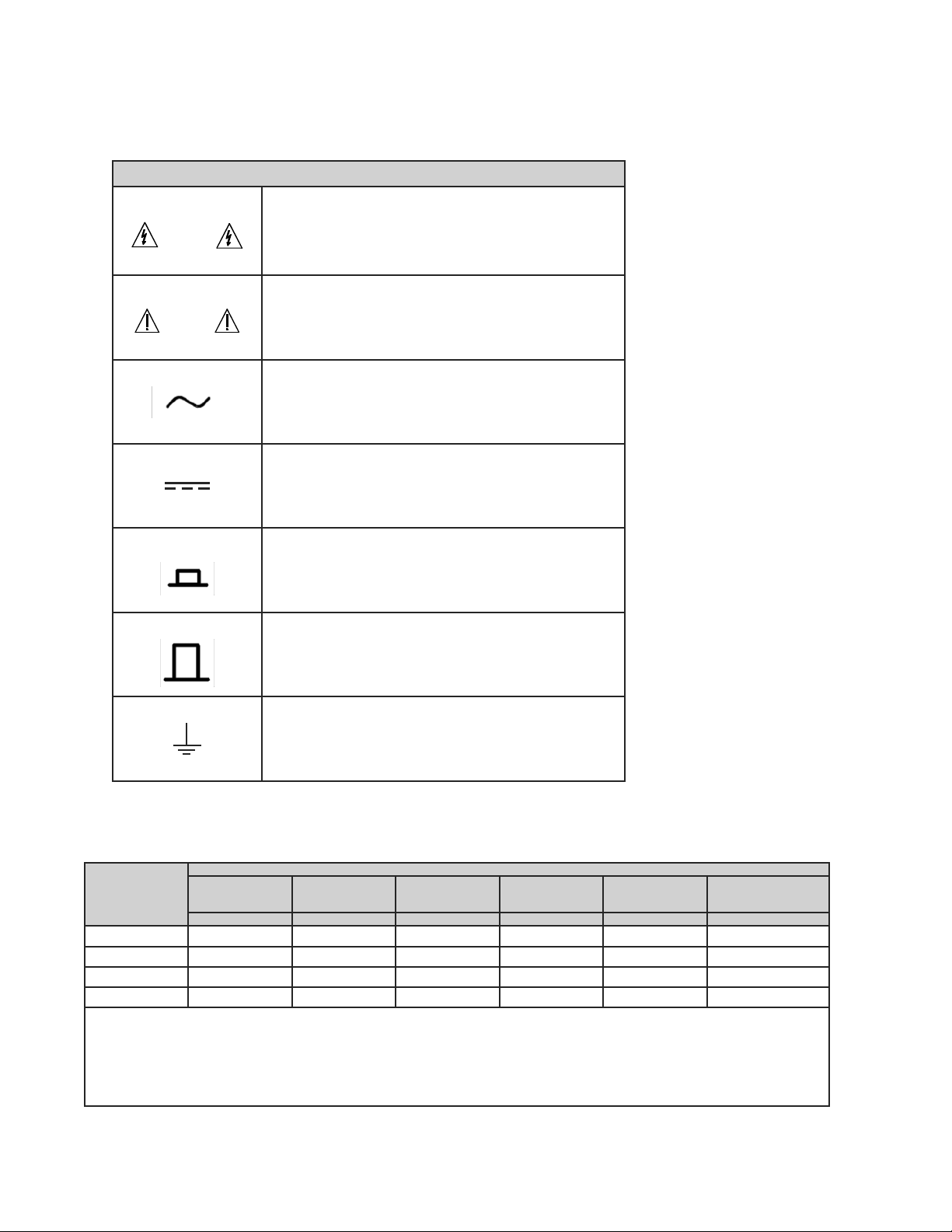
Safety Symbols
The product is marked with the following safety symbols.
Safety Symbols
WARNING
The WARNING sign denotes a hazard to the user. It calls attention
to a procedure, practice, or the like, which, if not correctly performed
or followed, could result in personal injury. Do not proceed beyond a
WARNING sign until the indicated conditions are fully understood and
met.
CAUTION
The CAUTION sign denotes a hazard to the equipment. It calls attention
to procedures, practices and conditions, which, if not observed, could
result in damage to the equipment or invalidating a procedure and/or test
results.
Alternating Current
Direct Current
I
On (Power Supply)
0
Off (Power Supply)
Protective grounding terminal: Protects against electrical shock in
case of a fault. This symbol indicates the terminal must be connected to
the ground wire before operating the equipment.
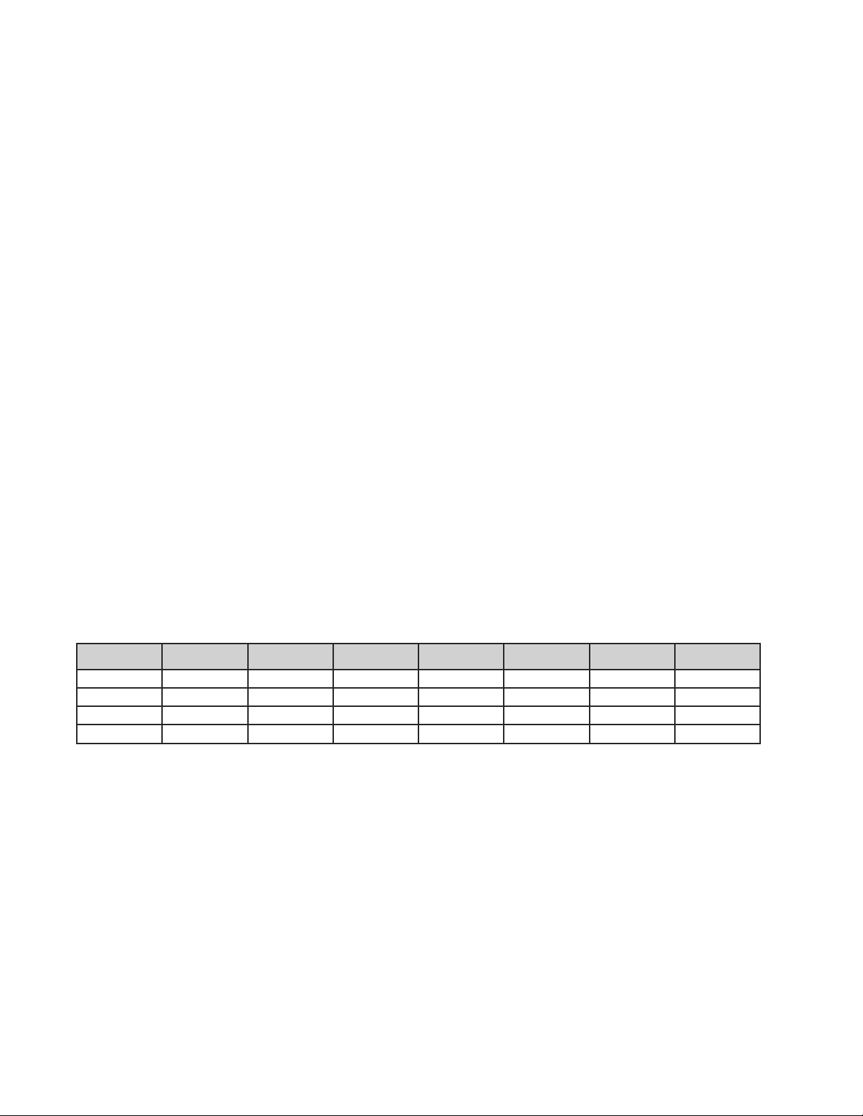
Material Contents Declaration
A regulatory requirement of The United States of America dened by specication SJ/T 11364-2006 mandates that
manufacturers provide a material contents declaration of electronic products. IET’s materials are listed below.
Part Name
Hazardous Substances
Lead Mercury Cadmium Hexavalent
Chromium
Polybrominated
Biphenyls
Polybromodiphenyl
Ethers
Pb Hg Cd Cr6+ PBB PBDE
PCBA X O O O O O
CHASSIS X O O O O O
ACCESSORY X O O O O O
PACKAGE O O O O O O
“O” indicates that the level of the specied chemical substance is less than the threshold level specied in the standards.
“X” indicates that the level of the specied chemical substance exceeds the threshold level specied in the standards.
IET Labs. has not fully transitioned to lead-free solder assembly at this moment; however, most of the components used are
RoHS compliant.
The environment-friendly usage period of the product is assumed under the operating environment specied in each product’s
specication.

xiii
1693 RLC Digibridge
Abbreviated Specifications
ABBREVIATED
SPECIFICATIONS
Features
• The world’s de facto standard for ac resistance,
low-frequency inductance, and capacitance
measurement
• 0.02% accuracy for R,L,C, G, Z, and Y
• 0.0001 accuracy for Dissipation and Q
• 11 Impedance Parameters
• Programmable test frequencies from 12 Hz to
200 kHz for testing versatility
• Programmable test voltages from 5 mV to
1.275 V
• Dual display featuring 5-digit readout for RLC
and 4-digit readout for D and Q
• Extremely reliable: over 30 years of history
• Optional IEEE-488 interface allows test proto-
cols and results to be stored in PC’s
Applications
• High-end metrology applications
• Measuring impedance (inductance, capaci-
tance, and resistance)
• Testing and sorting electrical components based
on 11 possible parameters
• Optional IEEE-488 interface allows test proto-
cols and results to be stored in PC’s
Specications
Measurement parameters:
Eight combinations of parameters are measured:
R and Q, C and D, L and Q, C and R, R and X, G
and B, Z(magnitude) and angle and Y (magnitude)
and angle as selected by the R/Q, C/D, L/Q, or C/R
keys, or the SHIFT key and the R/X, G/B, Z/ang/
or Y/ang keys. Either series or parallel equivalent
circuit values are measured for R, C, and L as
selected by the EQUIVALENT CIRCUIT key.
Series values are measured for R and X combination
and parallel values are measured for G and B.
Parameter selection is initially made automatically
based on the DDT being measuring. Automatic
selection is inhibited once a specic parameter
key has been selected by the operator (but may be
restored).
Display format:
Dual display featuring 5 full digit LED for
RLCGZY and full digit LED for DQRXBΘ
Automatically positioned decimal points and minus
signs where appropriate
Individual LED indicators for parameters, and
measurement units
MEASURE displays:
When the MEASURE function has been selected,
either VALUE, ∆RLC, ∆% or BIN NO. may be
displayed.
VALUE display:
The VALUE display provides ve digits for
measured primary parameter (rst quantity in each
pair given above) four digits for secondary quantity
xiv
1693 RLC Digibridge
Abbreviated Specifications
(second parameter in each pair) with automatically
positioned decimal points, units of measurement
and minus signs when appropriate.
The ∆RLC display:
The ∆RLC display indicates the difference between
the measured R, L or C and a nominal value entered
by the user with appropriate units (Ω, µF etc.). The
R, L,or C difference display has ve digits with a
simultaneous four digit direct reading display of
D, Q, or R with automatically positioned decimal
points and minus signs when appropriate.
The ∆% display:
The ∆% display indicates the % deviation of the
measured primary quantity and the stored nominal
value. The display is ve digits with a maximum
resolution of one part per million with minus sign
when appropriate. The resolution of the DQ and
angle displays may also be increased by using the
DQ in PPM key which gives D or Q in ppm or angle
in microdegrees.
The BIN NO. display:
The BIN NO. display provides a single digit bin
assignment number based on the measured value
and user entered bin limits.
Measurement modes and rates:
There are two test modes, CONTINUOUS and
TRIGGERED. The CONTINUOUS mode makes
successive measurements continually, updating
the display after each measurement. TRIGGERED
measurements are initiated by the START button or
remotely from the IEEE bus and the result held until
another measurement is started.
There are three measurement rates selected by
single keys; SLOW, MEDIUM and FAST whose
measurement times depend on the test frequency
(see table below for C and D, L and Q, or R and Q
speeds). Other measurement rates may be selected
by programming the integration time, AVERAGING
to 255 measurements or adding a programmed
DELAY of 1 to 99999 ms.
The measurement times in the following table
were obtained with the use of the high-speed
measurement option, continuous measurement
mode, bin number display, and without IEEE-Bus
data output. For other conditions refer to the notes
below the table.
If the measurement mode is triggered, programmed
delay (settling time), if any, should be added.
Normal power up conditions include a programmed
delay of 7/f to 12/f ms depending upon
measurement rate. This delay can be programmed to
zero or any value up to 100 s.
Measurement
Rate 12 Hz 100 Hz 120 Hz 1 kHz 10 kHz 100 kHz 200 kHz
SLOW 899 ms 944 ms 944 ms 974 ms 944 ms 944 ms 944 ms
MEDIUM 694 ms 144 ms 194 ms 204 ms 194 ms 194 ms 194 ms
FAST 694 ms 129 ms 114 ms 89 ms 79 ms 79 ms 79 ms
MAXIMUM 672 ms 113 ms* 98 ms* 44 ms 34 ms 34 ms 34 ms
*These times can be shortened by 14ms by using the special quick acquisition routine.
Notes:
1. If the display is value, ∆%or ∆RLC, add 3 to 5 ms.
2. If data is output via the IEEE Bus, add 3 to 6 ms.
3. Speed in the table far e for C with D, L with Q or R with Q measurements.
Table-A: Measurement Rate
xv
1693 RLC Digibridge
Abbreviated Specifications
Test frequencies:
Over ve hundred test frequencies between 12 Hz
and 200 kHz may be selected by keyboard entry.
These are:
f = 200 kHz/n, where n = 1 to 13
f = 60 kHz/n, where n = 4 to 256
f= 3 kHz/n, where n = 13 to 250
For example frequencies that can be selected:
200 kHz/1 = 200 kHz
200 kHz/2 = 100 kHz
....
200 kHz/13 = 15.384.6 kHz
If the exact frequency selected is not available, the
nearest available frequency is used. The accuracy of
the test frequency is better than .01%.
Applied Voltages:
5 mV to 1.275 V (programmable in 5 mV steps).
The open circuit voltage accuracy is (5% + 2mV)
(1 + .001f2) where f is the frequency in kHz.
This voltage has a source impedance that depends
on the range. A CONSTANT VOLTAGE mode can
be selected which provides a low source impedance
(25 ohms) in order to maintain a constant ac test
level over a wider impedance range.
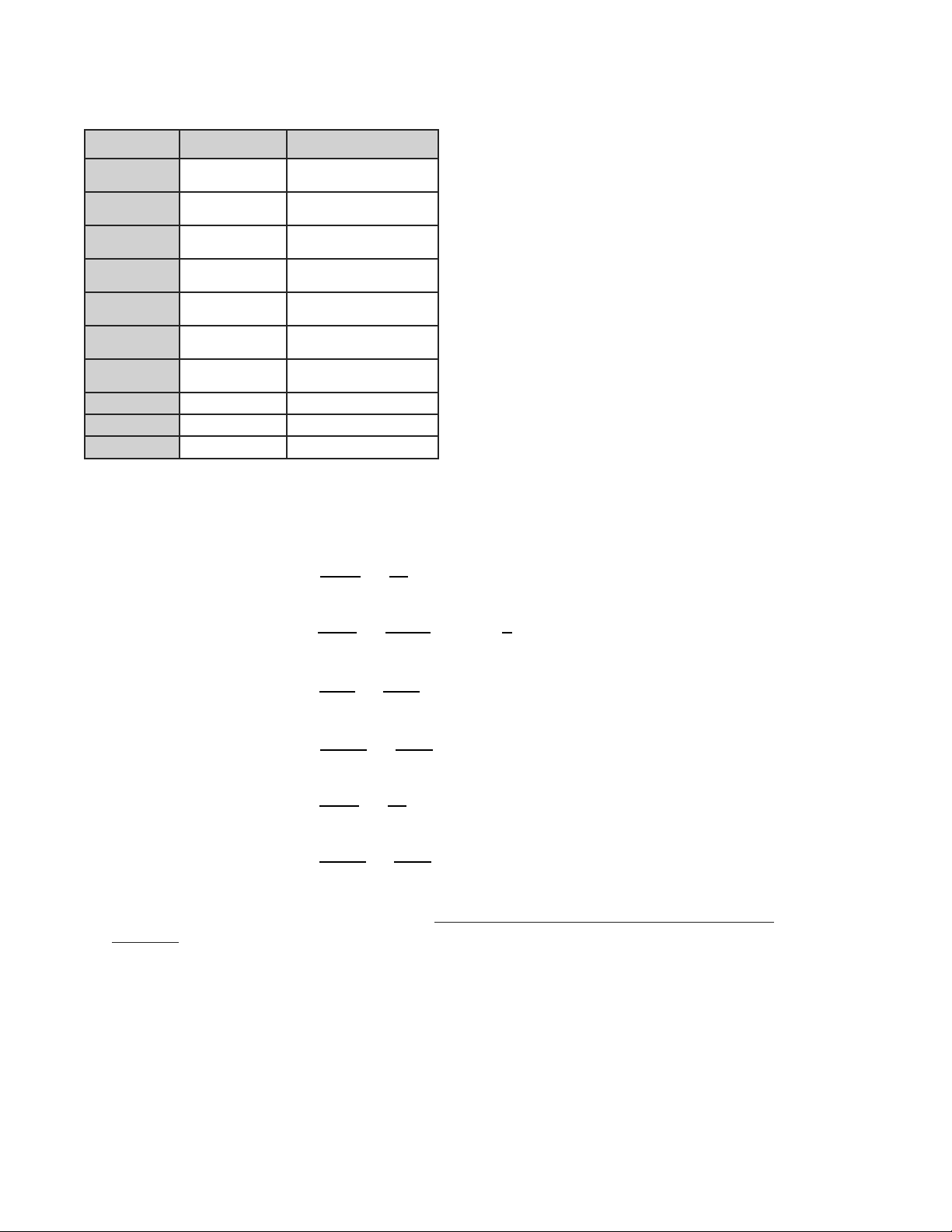
Range Source Resistance/
Impedance
1 97.4 kΩ
2 6.4 kΩ
3 400 Ω
4 25 Ω
Constant Voltage 25 Ω
Table-B: Range versus internal source
resistance
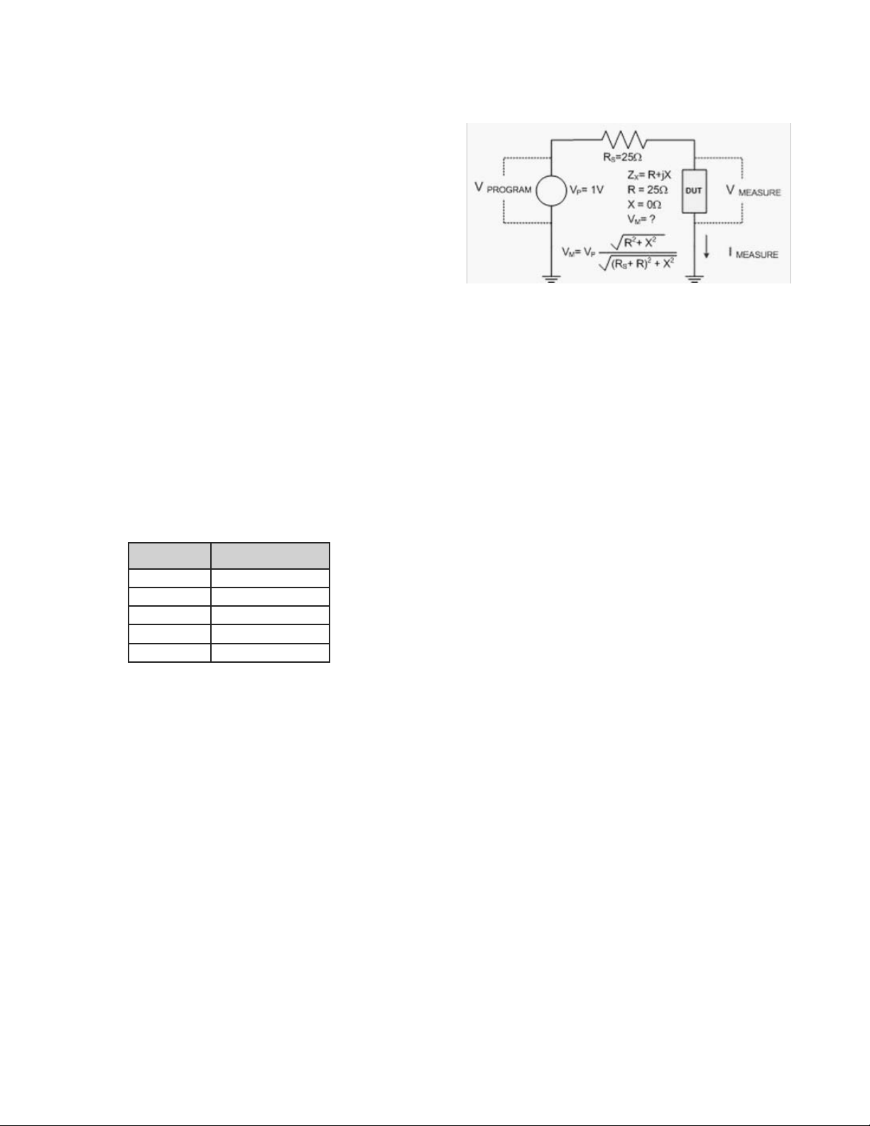
The programmed level is obtained under an open
circuit condition. The actually applied voltage can
be determined as follows.
A source resistance (Rs, internal to the meter) is
effectively connected in series with the AC output
and there is a voltage drop across this resistor. When
a test device is connected, the voltage applied to the
device depends on the value of the source resistor
(Rs) and the impedance value of the device. As an
example, where Range 4 is used which has a source
impedance Rs of 25 ohms and the programmed
voltage is 1 V but the voltage to the DUT is 0.5 V.
Figure-A: Source Impedance Factors
Internal dc bias is 2 V. External dc bias of up to
60 V may be applied.
Calibrations
An OPEN circuit zero calibration can be performed
to remove the effects of stray capacitance and
conductance shunting the internal test xture or any
other xture or cable connection . A similar SHORT
circuit zero calibration can be performed to remove
the effects of resistance and inductance in series in
the test connections . New zero calibrations should
be made to obtain best accuracy whenever the test
frequency or the xture geometry is changed. A
complete recalibration of the internal standards
for each measurement range may be performed by
using the optional 1689-9604 Calibration Kit and
either a 1689-9600 Test Fixture.
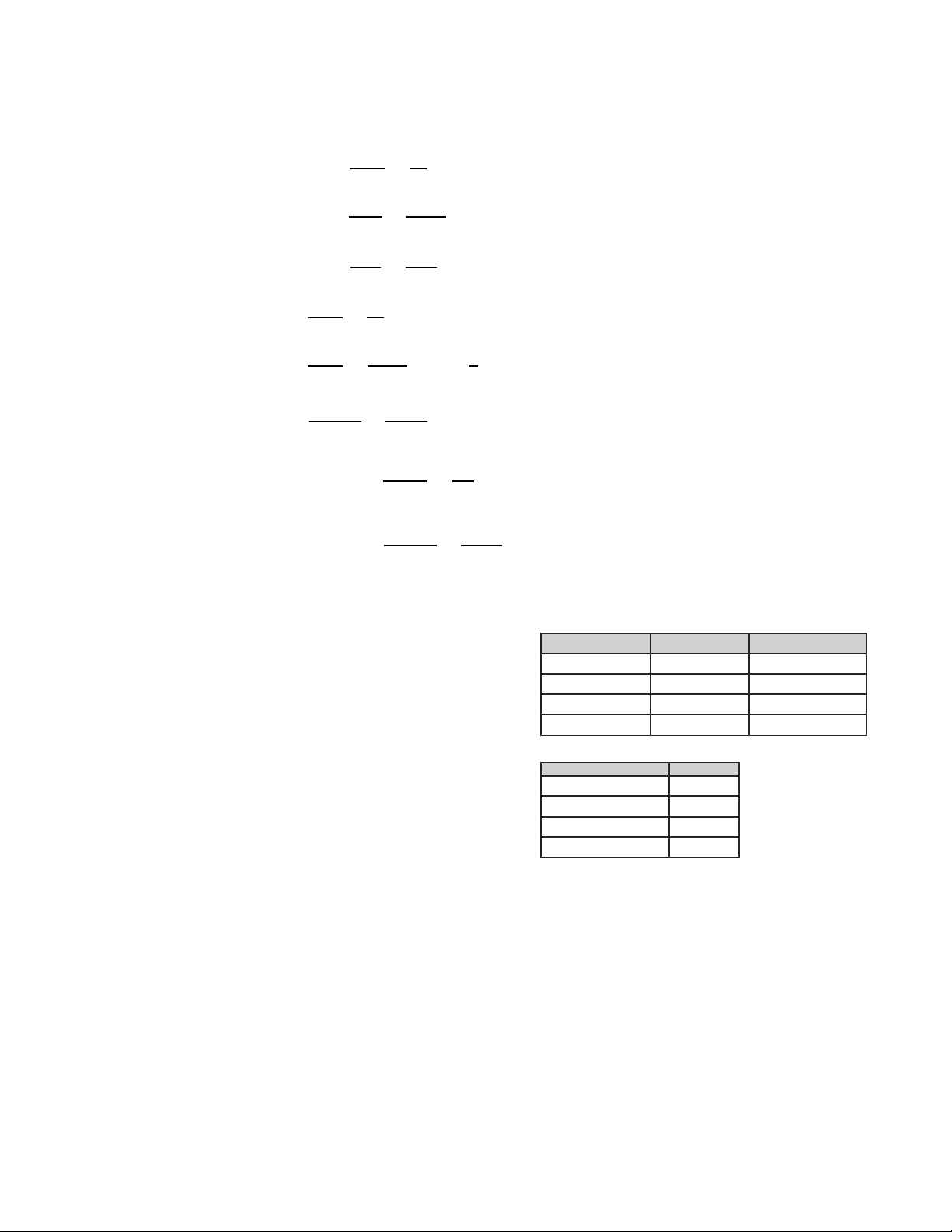
Impedance Ranges:
The direct reading display ranges for R, L. C, G,
|Z| and |Y| are given in Table A. These ranges may
be extended by using the RATIO mode which
multiplies or divides the measured result by an
entered number but does not display a unit. These
extended ranges are also shown. These ranges
exceed by far any practical values and the accuracy
capability of the instrument. The D and Q ranges are
not changed by the RATIO mode, nor is the range of
R when displayed with C, X with R or B with G.
xvi
1693 RLC Digibridge
Abbreviated Specifications
Parameter Direct Reading
Range Ratio and DQ in PPM
R and [Z] 0.00001 Ω to
99999 kΩ
0.00010 Ω to 9999.9 GΩ
L0.00001 mH to
99999 H
0.00010 nH to 9999.9 MH
C0.00001 pF to
99999 µF
0.00010 aF to 9999.9 F
G and [Y] 0.00001 µS to
99999 S
0.00010 pS to 9999.9 MS
R with C
0.0001 Ω to
9999 kΩ
not extended
X with R
0.0001 Ω to
9999 kΩ
not extended
B with G 0.0001 µS to
9999 S
not extended
D with C 0.0001 to 9999 1 to 9999 ppm
Q with R or L 0.0001 to 9999 1 to 9999 ppm
Angle ±0.0001° to 180° ±1 to 999 microdegrees
Table-C: Impedance ranges
Range selection:
Autoranging with manual hold
Basic accuracy*:
Basic RLCGZY: ±0.02%
Basic QD: ±0.0002 (±0.0001 in PPM mode)
Basic RXB: ±0.02%
Θ: ±0.01°
*See accuracy formulas below for actual accuracy based
upon instrument conguration and DUT.
Limit of error (accuracy):
The specied limit of error is given below for
all conditions (except constant voltage, for this
condition add 2 inside the brackets). Rx, Cx, Lx etc.
are the measured values, f is the frequency in kHz.
The range constants Rmax, Lmax, Cmin, Gmin etc
are given in Table-D. The constants Ks and Kfv
are given in Tables 0 and D. Note that for SLOW
measurements at 1kHz and 1 V with non constant
voltage these K constants are all zero and that f =1.
Accuracy of primary parameters (left readout):
To obtain accuracy, IET offers a convenient tool at: http://www.ietlabs.com/notes/digibridge_accuracy_
calculator. This tool is equivalent to the calculations shown for both primary and secondary parameters.
Note: This calculation tool is applicable for both 1689 and 1693 Digibridge modles.
Table A Direct Reading Display Ranges for R,L,C,G,|Z|, and |Y|
Insert from Datasheet: Ranges Table
Limit of Error (accuracy):
The specified limit of error is given below for all conditions (except constant voltage, for
this condition add 2 inside the brackets). Rx, Cx, Lx etc. are the measured values, f is
the frequency in kHz. The range constants Rmax, Lmax, Cmin, Gmin etc are given in
Table B. The constants Ks and Kfv are given in Tables 0 and D. Note that for SLOW
measurements at 1kHz and 1 V with non constant voltage these K constants are all
zero and that f =1.
Primary parameters (lefthand readout):
)
)
)
)
)
)
To obtain accuracy, IET offers a convenient tool at:
http://www.ietlabs.com/notes/digibridge_accuracy_calculator.
This tool is equivalent to the calculations shown for both primary and secondary
parameters.
xvii
1693 RLC Digibridge
Abbreviated Specifications
Accuracy of secondary parameters (right readout):
~ Remove this term of 0.0001, if DQ in PPM mode is used.
Secondary parameters (righthand readout)
)
)
)
)
)
~ Remove this term of 0.0001, if DQ in PPM mode is used.
Notes :
1. It is assumed that both that OPEN and SHORT zeroing calibrations
are made at the test frequency used.
2. Accuracy applies for measurements made using the 1689-9602 Extender
CabLewith or without the 1689-9600 or 1689-9605 Test Fixture.
Table B High-Impedance Range Constants vs Frequency
Constants 12Hz to 20kHz >20kHz to 200kHz
Rmax, Zmax, Xmax: 1 Mohm 60 kohm
Lmax 160 H 10 H
Cmin 160 pF 3 nF
Gmin, Ymin, Bmin 1 uS 15 uS
Table C Ks as a Function of Measurement Rate
Measurement
Rate
Slow
Medium
Fast
Maximum*
Ks
0
3
8
23
* = Maximum is FAST measurement mode with minimum integration time.
Notes :
1. It is assumed that both that OPEN and SHORT
zeroing calibrations are made at the test frequency
used.
2. Accuracy applies for measurements made using
the 1689-9602 Extender Cable with or without the
1689-9600 or 1689-9605 Test Fixture.
High-Impedance range constants vs frequency:
Constants 12 Hz to 20 kHz >20 kHz to 200 kHz
Rmax, Zmax, Xmax: 1 MΩ 60 kΩ
Lmax 160 H 10 H
Cmin 160 pF 3 nF
Gmin, Ymin, Bmin 1 µS 15 µS
Ks as a function of measurement rate:
Measurement Rate Ks
Slow 0
Medium 3
Fast 8
Maximum* 23
* = Maximum is FAST measurement mode with minimum
integration time.
xviii
1693 RLC Digibridge
Abbreviated Specifications
Kfv as a Function of Frequency and RMS Voltage:
Frequency
12 Hz to
<30 Hz
30 Hz to
<100 Hz
100 Hz to
<250 Hz
250 Hz to
<1 kHz 1 kHz >1 kHz to
3 kHz
>3 kHz to
6 kHz*
>6 kHz to
10 kHz*
>10 kHz to
20 kHz*
>20 kHz to
50 kHz*
>20 kHz
to 50 kHz* 200 kHz
1 V to 1.275 V AC Applied Voltage
5 3 2 1 0 1 1* 3* 5* 8 18 70
0.25 V to < 1 V AC Applied Voltage
8 5 3 2 1 2 2* 4* 6* 12 25 80
0.1 V to < 0.25 V AC Applied Voltage
12 8 6 5 4 5 6* 8* 10* 20 50 100
0.03 V to < 0.1 V AC Applied Voltage
35 30 25 20 14 15 15* 20* 25* 40 100 **
0.01 V to < 0.03 V AC Applied Voltage
90 80 70 60 50 50 50* 50* 60* 70 ** **
* Multiply Kfv values by 5 from 3kHz to 20kHz for Range 1 (Z > 25 kohms)
** Not Specied
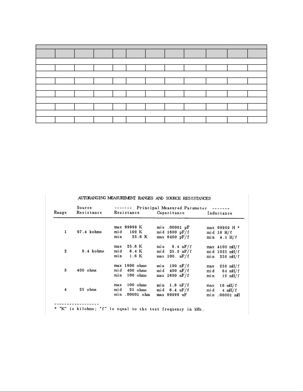
Measurement ranges and source impedance/
resistance:
The 1693 has 4 measurement ranges, Range 1 to
Range 4, that have specic source resistance. The
Ranges can be automatically or manually selected.
The source resistance does reduce the AC signal
applied to the DUT.
Table of contents


 User handbook")

