Boonton 213-A User manual

OPERATING
INSTRUCTIONS
FOR
THE
PHASE
TEST
SET
TYPE
213-A
Boonton
Radio
Corporation
P.O.
Box
390
Boonton,
New
Jersey,
U.S.A.


OPERATING
INSTRUCTIONS
Contents
Description
Theory
of
Operation
"307V
Bridge"
Measurements
"Direct"
Measurements
Sweep
Circuits
Specifications
and
Characteristics
"30
/U
Bridge"
Operation
"Direct"
Measurements
Method
of
Operation
Auxiliary
Equipment
Adjustment
of
the
211A
Signal
Generator
for
zero
phase
shift
at
50/3/
Interconnection
of
Equipment
Calibration
Adjusting
the
2114
Signal
Generator
for
zero
shift.
Phase
Shift
Measurements
on
the
211A
Signal
Generator
between
20л
and
11,0004Ј
per
second
Illustrations:
Fig.
1
Simplified
Diagram
showing
the
"3049
Bridge"
operation
of
the
Phase
Test
Set
2
Block
Diagram
showing
operation
of
the
Phase
Test
Set
for
"Conventional"
Phase
Measurements
5
Inter-Connection
Diagram
,
Schematic
Parts
List
©
№
о
№№
Fee
мым


DESCRIPTION
The
PHASE
TEST
SET
was
developed
to
provide
a
simple
yet
pre-
cise
method
of
measuring
and
adjusting
overall
phase
shift
іп
the
Type
211A
Omi-Range
Signal
Generator,
It
is
furnished
complete
with
all
interconnecting
cables
but
requires
the
use
of
an
auxiliary
audio
oscillator
and
oscilloscope,
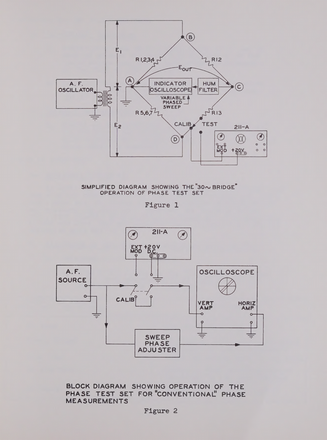
THEORY
OF
OPERATION
А.
"30
BRIDGE"
Measurements
(See
Fig.
1)
For
this
method
of
operation
the
PHASE
TEST
SET
is
switched
to
produce
two
30~signals
of
exactly
equal
amplitude
but
opposite
phase
(El
and
Е2),
These
are
combined
to
produce
a
balanced
("null")
condition
of
zero
output
to
the
indicator
circuits
(Eout=0)
е
One
arm
of
this
balanced
bridge
is
now
opened,
and
the
211A
circuits
are
inserted
in
series
with
this
arm,
The
211A
is
now
adjusted
to
produce
the
same
bridge
condition
as
the
short
cir-
cuit
it
replaced,
Amplitude
balance
is
restored
by
adjusting
the
modulation
level
control
of
the
211A
to
produce
unity
voltage
gain
through
the
211A3
any
remaining
unbalance
voltage
at
the
bridge
output
(Bout)
is
due
to
phase
shift,
and
is
directly
pro-
portional
to
the
amount
of
shift,
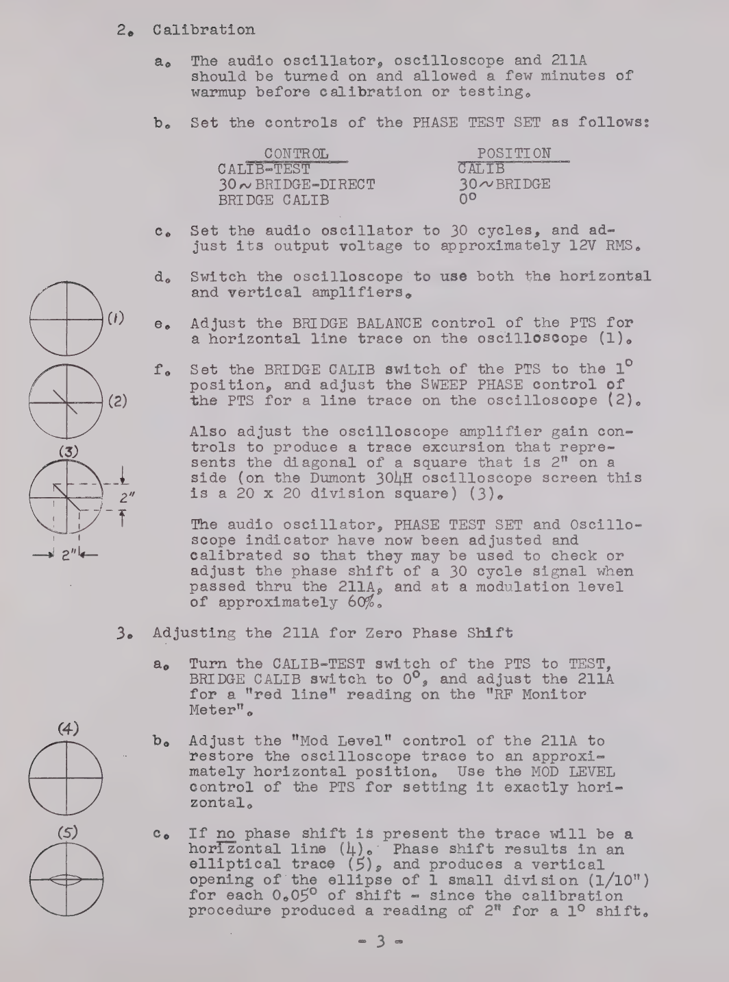
В,
Conventional
"Direct"
Measurements
(See
Fig.
2)
By
switching
the
controls
of
the
PHASE
TEST
SET,
phase
measurements
at
any
frequency
between
20
cycles
and
11,000
cycles
may
be
made
by
the
conventional
scope
trace
method,
С.
Sweep
Circuits
A
variable
phase
sweep
output
is
provided.
Approximately
180°
of
continuous
phasing
adjustment
is
provided,
This
range
of
sweep
adjustment
allows
the
oscilloscope
presentation
of
the
30
BRIDGE
unbalance
voltage
to
be
adjusted
so
that
an
amplitude-produced
unbalance
voltage
will
cause
a
tilt
of
the
line
trace
and
а
phase-produced
unbalance
voltage
will
cause
an
opening
of
the
line
to
form
an
ellipse.
The
wide
range
of
available
sweep
phasing
adjustment
also
allows
correction
to
be
made
for
phase
shifts
within
the
oscilloscope
amplifiers
when
checking
shift
by
the
conventional
150
trace
method,
a
р"

ay,
0
i
|
0
Я
|
\\
ў 0
4
Ж
үп
1
i Y
un
HAN
A
тг
і
у
1
т
4
(у
EDS
ји
Я
|
21
|
1
тен
e
i
ї
4
Т
f | 1
[|
ү
|
|
}
|
:
De
ү
|
|
|
|
лу
AINE
a
wile
0
|
р у
d'a
FUN
94
ГЖ:
і
ў
Ч
0229
at
|
"Қ
МЛ!
fr
||
7
Ч
118
Y
i
р
ME
Ку
i
|
!
ў
Ы
?
№
\
Р
і
К
ч
y
|
Й
,
|
е
(
f |
Í
Л
|
1
| Г.
к
ў
À
у
у
7
у
|
1
!
7)
|
|
де
"а
у
i
Li
|
er
|
i
(
|
ЈЕ]
À
À
ў,
|
|
)
'
|
Ча.
МІ
77
У
4
be
y
i
|
Ñ
! (
04
|
!
!
А
er
Я
т
фу,
т
N
й
Т)
| р |
|
|
р
|
1)
|
ў
Ж
Ч
к
у
1
iy
2
i
А
|
À
ТІ
i
й
1
ў
f
Т
a
$
і
М
й
б
1
ў
n
мор,
|
2
(
2
il
y
қ
кебінін
Ақан
Ж
ў
ў
И
|
ЫГ
7
ў
VARIABLE
PHASED
SIMPLIFIED
DIAGRAM
SHOWING
THE
"30~
BRIDGE"
OPERATION
OF
PHASE
TEST
SET
Figure
1
PHASE
ADJUSTER
BLOCK
DIAGRAM
SHOWING
OPERATION
OF
THE
PHASE
TEST
SET FOR
"CONVENTIONAL
PHASE
MEASUREMENTS
Figure
2

и
Түр!
Т
г
i
Мм
үү
МАРУ
Я
хон
оны
ашыта
!
\
“...
А
у
ін
ТИ

SPECIFICATIONS
AND
CHARACTERISTICS
А.
"30/VBRIDGE"
Operation.
1,
Sensitivity
such
that
a
phase
shift
of
1°
can
be
made
to
produce
at
least
a
2"
deflection
on
the
oscilloscope
screen
for
modulation
percentages
of
the
211A
of
30%
or
greater,
2.
Self
calibrating
for
measurements
of
phase
shift
with
a
calibration
error
of
less
than
0,19
when
the
1°
BRIDGE
CALIB
position
is
used,
В.
"DIRECT"
Measurements
1,
Useful
at
any
modulation
frequency
between
20
and
11,000
cycles
per
second
(must
be
phased
and
have
gain
adjusted
at
each
modulation
frequency
at
which
phase
shift
is
checked),
METHOD
OF
OPERATION
А.
Auxiliary
Equipment
An
audio
oscillator
and
an
oscilloscope
are
necessary
for
use
with
the
PHASE
TEST
SET,
The
Hewlett-Packard
2018
audio
oscillator
and
the
Dumont
ЗОЦН
oscilloscope
have
been
found
satisfactory
for
this
use,
However,
any
standard
audio
oscillator
capable
of
delivering
at
least
20V
of
signal
into
a
1000
ohm
load,
and
any
standard
oscilloscope
with
moderate
amplifier
gain
may
be
used,
Be
LA
for
ze
Adjustment
of
the
21
го
Phase
Shift
at
30/
Le
Interconnection
of
Equipment
а,
Attach
all
cables
to
the
PHASE
TEST
SET,
The
cable
with
detachable
phone
plug
should
be
connected
бо
the
TO
TEST
jack,
CABLE
FROM JACK
ON
(PRA
ма
зиз
стае
PHASE
TEST
SET
MARKED:
|
БОЛЕК
То
Test
|
EXT
MOD
jack
of
the
2114
Sweep
Output
|
Horizontal
("X")
amplifier
input
|
terminals
of
the
oscilloscope
From
Test
|
"4207
DC"
demod
posts
of
the
2114
|
To
Indicator
Vertical
("Ү")
amplifier
input
|
terminals
of
the
oscilloscope
AF
Input
|
Output
of
the
АР
oscillator

”
|
ІШ
у
de
LN
Жү
|
217
1
го
0
Кана
7
ee
Уй
йг
|
|
МЕ
“т
ла,
124
%
7!)
5.
0
1
ua
а
ы
4
7
А.
ГУ
Жж”
Ч
MITA
84)
|
«ў
Маа
IL
a
|
422227
+>
і
\
Ма
|
14
ТР
БГД.)
УМ
Р
j
RENE
у
(7!
АН
!
per
у
{
м
|
ік
ы
ver
|
Г
17
i
(9
|
6.
Wai
у
i |
{
17
i
т
24
?
шы
М
2202
к
5
ь
ёй
!
|
р
Ї
у
a
ee
Le
|
| 1
р
б
pes
|
ИАА
у
Й
|
М
{
|
LUN
1
137
|
|
AL
UE
Ч
1
à
У
ТЫ;
|
|
O
ШТ!
Лимон
)
ил
ТҮЙЕ.
i
ча
1
Ї 1
(
у
А
one.
|
|
>
т
ау
б
|
ҮГІТ!
і
|
)
ч
A
В
|

21!-А
PHASE
TEST
SET
OSCILLOSCOPE
FROM
TEST
©
RED
TIP”
INTER
–
CONNECTION
DIAGRAM
Figure
3

)
1
O
„дї
"Эф
ШІ
i
2,
Calibration
ао
The
audio
oscillator,
oscilloscope
and
211А
should
be
turned
on
and
allowed
a
few
minutes
of
warmup
before
calibration
or
testing,
р.
Set
the
controls
of
the
PHASE
TEST
SET
as
follows:
CONTROL
POSITION
CALIB-TEST
ALIB
30
~
BRIDGE=DIRECT
30~
BRIDGE
BRIDGE
CALIB
oc
с,
Set
the
audio
oscillator
to
30
cycles,
and
а4-
just
its
output
voltage
to
approximately
12V
RMS.
do
Switch
the
oscilloscope
to
usé
both
the
horizontal
and
vertical
amplifiers,
(1)
е,
Adjust
the
BRIDGE
BALANCE
control
of
the
PTS
for
a
horizontal
line
trace
on
the
oscillossope
(1),
Г.
Set
the
BRIDGE
CALIB
switch
of
the
PTS
to
the
1°
position,
and
adjust
the
SWEEP
PHASE
control
of
(2)
the
PTS
for
a
line
trace
on
the
oscilloscope
(2).
Also
adjust
the
oscilloscope
amplifier
gain
соп-
trols
to
produce
a
trace
excursion
that
repre-
sents
the
diagonal
of
a
square
that
is
2"
ona
side
(on
the
Dumont
ЗОДН
oscilloscope
screen
this
is
a
20
x
20
division
square)
(3).
|
The
audio
oscillator,
PHASE
TEST
SET and
Oscillo-
scope
indicator
have
now
been
adjusted
and
—
г"
calibrated
so
that
they
may
be
used
to
check
or
adjust
the
phase
shift
of
a
30
cycle
signal
when
passed
thru
the
211A,
and
at
a
modulation
level
of
approximately
60%,
3,
Adjusting
the
211A
for
Zero
Phase
Shift
ао
Turn
the
CALIB-TEST
switch
of
the
PTS
to
TEST,
BRIDGE
CALIB
switch
to
09,
and
adjust
the
211A
for
a
"ред
line"
reading
on
the
"RF
Monitor
Meter",
4)
|
A
b,
Adjust
the
"Mod
Level"
control
of
the
211A
to
restore
the
oscilloscope
trace
to
an
арргохї-
mately
horizontal
position,
Use
the
MOD
LEVEL
control
of
the
PTS
for
setting
it
exactly
hori-
zontal.
(5)
Co
If
no
phase
shift
is
present
the
trace
will
be
а
horizontal
line
(Д).
Phase
shift
results
in
an
elliptical
trace
(5),
and
produces
a
vertical
opening
of
the
ellipse
of
1
small
division
(1/10")
for
each
0,050
of
shift
=
since
the
calibration
procedure
produced
a
reading
of
2"
for
a
1°
shift,
аа


Ce
Phase
Shift
Measurements
between
20
and
11,000
Cycles
per
second
(By
conventional
Scope
trace
method)
le
г.
do
е.
Adjustment
of
the
211-А
for
zero
shift
18
now
accomplished
by
alternately
setting
the
phasing
control
of
the
211А,
P306,
and
then
re-
storing
the
trace
on
the
oscilloscope
to
hori-
zontal
using
the
"Mod
Level"
control
of
the
211A
and
the
MOD
LEVEL
vernier
control
on
the
PTS,
This
is
repeated
until
a
horizontal
line
trace
is
obtained,
As
a
double
check
that
the
correct
setting
has
been
obtained,
switch
the
CALIB-TEST
Control
of
the
PTS
to
CALIB.
The
resultant
trace
should
be
a
horizontal
line,
proving
that
the
PTS
is
still
correctly
calibrated,
NOTEg
Phase
shift
in
the
211A
may
be
checked
at
any
percentage
of
modulation
between
approximately
10
and
100%
by
resetting
the
out-
put
level
of
the
audio
oscillator
and
repeating
the
calibration
procedure
previously
outlined,
Interconnection
of
equipment,
This
is
identical
to
that
previously
described,
Calibration
(must
be
repeated
for
each
audio
free
quency
at
which
it
is
desired
to
measure
phase
shift)
а,
be
de
Set
the
controls
of
the
PHASE
TEST
SET
as
Follows:
[
CONTROL
|
POSTTION
—
CALIB-TEST
CALIB
|
30
BRIDGE=DIRECT
|
DIRECT
|
BRIDGE
CALIB___
OE
AT
Set
the
audio
Oscillator
to
produce
an
output
of
SV
RMS
at
the
frequency
at
which
it
is
desired
to
measure
the
phase
shift,
Adjust
the
SWEEP
PHASE
control
of
the
PTS and
the
oscilloscope
amplifier
gain
controls
бо
produce
a
1,59
hair
line
trace
which
represents
the
diagonal
of
a
2"
square
(20
x
20
division
square
on
the
Dumont
ЗОДН)
(6),
|
Measure
the
RMS
voltage
at
the
input
terminals
of
the
oscilloscope
vertical
("Ү")
amplifier,
and
increase
it
бо
2,9
times
158
measured
value
by
increasing
the
output
of
the
audio
oscillator.
2

pate
М
АТА
М
к
я
ү

30
es
Switch
the
CALIB-TEST
switch
of
the
PTS
to
its
TEST
position
and
adjust
the
"Mod
Level"
con-
trol
of
the
211A
to
restore
а
Ц5?
trace
on
the
oscilloscope
(or
alternately
to
provide
the
same
RMS
voltage
at
the
vertical
("Y")
amplifier
input
terminals
of
the
oscilloscope
аз
was
рго-
duced
in
the
preceding
step
(4),
Measurement
The
pháse
shift
may
now
be
measured
by
observing
the
vertical
distance
between
the
two
trace
lines
as
they
cross
the
vertical
centerline,
and
18
direct
reading
(1
small
division
or
0,1
inch
=
19
when
setup
has
been
performed
such
that
a
20
x
20
division
trace
was
produced
and
then
expanded
2,9
times
(7).
(7)
expanded
view
of
center
of
oscilloscope
screen
wi
th
trace
showing
1°
shift;

72777

тї8г06
09088У
950987
609209
96409
86709
ЄТ9ТӨҮ
44409
2108
26108
Сгот8У
96Т08
а6тод
6109
220197
OTQZOEV
9T
128
1228
аөашақ
oud
мг/т
94+
¿T+
м/т
$S+
MT
MT
suyo
000008
suyo
000°00T
suyogsu
492
suyo
000°022
gor
suyo
0/4
ТҮ
suyo
696
suyo
ST
MT
ZT+
suyo
00T
MT
71%
suyo
дтег
MT
YT+
sumo
021
suyo
04
Tetoedg
gn
ТО”
та
€00°
JUTEN
ИТО44/,
Tousyduy
Зпта
Lada
Чэ31м5
10909198
1144
чэзтме
10909TOS
СС-ст
OLN
чэцаотвцва],
мотатводшоо
“рехтј
соалво
редтгодор
‘рэхту
мотатводшоо
Фәтавтсел
чотатвобшоо
*pexty
цотатвобшоо
*pexTty
punom
өдтм
“рәхту
punom
едтм
‘этазтаел
punom
едтм
срехтј
punom
өстм
“рэхтў
punom
өлтм
рәхтј
punom
әстм
ёетавтаел
$
додетвец
51015Т1594
“1048
[SƏY
5Х048ТБӨН
10481894
60461594
блоаатвоц
$1098STS9Y
$
203
8T89Y
6109S
TSOY
10981894
ssed-0TWO€
“18929TTH
вотш
рәхті
‘дозтозаво
вотш
рехтј
404108460
ЧОТ
120590
GH
E
Z
T-d
ес
18
Ti
“TY
Ст
гіч
т
OTH
6%9Ч
LE
94
ая
MEH
zu
TU
Ta
eco
ES
Toquks

Table of contents


