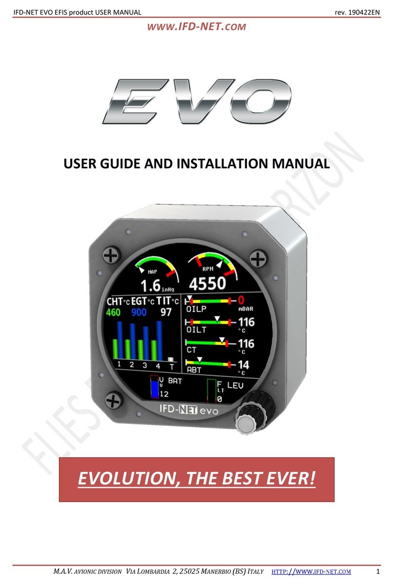
IFD-NET EVO Instruction Manual

IFD-NET EVO EMS USER MANUAL rev. 121022EN
WWW.IFD-NET.COM
M.A.V. AVIONIC DIVISION VIA LOMBARDIA 2, 25025 MANERBIO (BS) ITALY HTTP://WWW.IFD-NET.COM 3
Summary
1. INTRODUCTION 7
1.1. ELECTRICAL AND MECHANICAL SPECIFICATION 7
2. SYSTEM DECRIPTION 8
2.1. IFD-NET EVO EMS OVERVIEW 8
3. UNIT DESCRIPTION 9
4. OPERATION 10
4.1. PAGE EMS 10
4.1.1. SCREEN SECTION 1: TOP SCREEN 11
4.1.2. SCREEN SECTION 2: RIGHT SCREEN 12
4.1.3. SCREEN SECTION 3: LEFT SCREEN 13
4.1.4. SCREEN SECTION 3: BOTTOM SCREEN 14
4.2. SETUP MENU 15
4.2.1. MAIN SETUP 16
4.2.2. THERMOCOUPLES SETUP 17
4.2.3. SENSOR SETUP 19
4.2.4. RPM/FLOW SETUP 20
4.2.5. MAP/VBAT SETUP 21
4.2.6. CURVES SETUP 21
4.2.7. FUEL LEVEL CALIB SETUP 22
4.2.8. ARCS SETUP 22
5. CONNECTIONS 23
5.1. REAR CONNECTORS VIEW AND DESCRIPTION 23
5.2. POWER CONNECTOR 24
5.3. EXPANSION CONNECTORS 24
5.3.1. EXP. CONNECTOR (EMS1) 24
5.3.2. EXP. CONNECTOR (EMS2) 24
5.4. SENSORS AND THERMOCOUPLES WIRING 25
5.4.1. THERMOCOUPLES 25
5.4.2. THERMOCOUPLE WIRING EXAMPLE 25
5.4.3. VOLTAGE SENSORS NOTE 26
5.4.4. CURRENT SENSORS NOTE 26
6. INSTALLATION GUIDE 27
6.1. DISASSEMBLY/ASSEMBLY THE KNOBS 28
6.1.1. DISASSEMBLY STEPS 28
6.2. SELECTING AN APPROPRIATE INSTALLATION POSITION 29

IFD-NET EVO EMS USER MANUAL rev. 121022EN
WWW.IFD-NET.COM
M.A.V. AVIONIC DIVISION VIA LOMBARDIA 2, 25025 MANERBIO (BS) ITALY HTTP://WWW.IFD-NET.COM 4
7. ELECTRICAL CONNECTIONS 30
7.1. POWERING AND EXPANSION BUS 30
7.2. EMS POWER CONNECTOR 30
7.3. EMS MASTER SLAVES CONNECTION 31
7.3.1. WIRING SPECIFICATION 31
8. WIRING EXAMPLE 32
9. SYSTEM CONFIGURATION EXAMPLE 33
10. SENSORS LIST 34
11. MECHANICAL DIMENSIONS DIAGRAM 35
12. ORDERING INFORMATION 36

IFD-NET EVO EMS USER MANUAL rev. 121022EN
WWW.IFD-NET.COM
M.A.V. AVIONIC DIVISION VIA LOMBARDIA 2, 25025 MANERBIO (BS) ITALY HTTP://WWW.IFD-NET.COM 5
CERTIFICATE OF WARRANTY
LIMITED WARRANTY
Seller warrants that the product hereby purchased is, upon delivery, free from defects in material and workmanship
and that any such product which is found to be defective in such workmanship or material will be repaired or replaced
by Seller (M.A.V. srl via Lombardia, 2 25025 Manerbio BRESCIA Italy); provided, however, that this warranty applies
only to equipment found to be so defective within a period of lifetime from the date of manufacture by the Seller.
Seller shall not be obligated under this warranty for alleged defects which examination discloses are due to tampering,
misuse, neglect, improper storage, and in any case where products are disassembled by anyone other than authorized
Seller’s representatives.
EXCEPT FOR THE LIMITED WARRANTY OF REPAIR AND REPLACEMENT STATED ABOVE, SELLER DISCLAIMS ALL
WARRANTIES WHATSOEVER WITH RESPECT TO THE PRODUCT, INCLUDING ALL IMPLIED WARRANTIES OF
MERCHANTABILITY OR FITNESS FOR ANY PARTICULAR PURPOSE.
LIMITATION OF SELLER’S LIABILITY
SELLER’S LIABILITY TO BUYER FOR ANY LOSS OR CLAIM, INCLUDING LIABILITY INCURRED IN CONNECTION WITH
(I) BREACH OF ANY WARRANTY WHATSOEVER, EXPRESSED OR IMPLIED,
(II) A BREACH OF CONTRACT,
(III) A NEGLIGENT ACT OR ACTS (OR NEGLIGENT FAILURE TO ACT) COMMITTED BY SELLER, OR
(IV) AN ACT FOR WHICH STRICT LIABILITY WILL BE INPUTTED TO SELLER,
IS LIMITED TO THE “LIMITED WARRANTY” OF REPAIR AND/OR REPLACEMENT AS SO STATED IN OUR WARRANTY OF
PRODUCT. IN NO EVENT SHALL THE SELLER BE LIABLE FOR ANY SPECIAL, INDIRECT, CONSEQUENTIAL OR OTHER
DAMAGES OF A LIKE GENERAL NATURE, INCLUDING, WITHOUT LIMITATION, LOSS OF PROFITS OR PRODUCTION, OR
LOSS OR EXPENSES OF ANY NATURE INCURRED BY THE BUYER OR ANY THIRD PARTY.
M.A.V. srl
Via Lombardia, 2
25025 Manerbio BS
Italy

IFD-NET EVO EMS USER MANUAL rev. 121022EN
WWW.IFD-NET.COM
M.A.V. AVIONIC DIVISION VIA LOMBARDIA 2, 25025 MANERBIO (BS) ITALY HTTP://WWW.IFD-NET.COM 6
DICHIARAZIONE DI LIMITAZIONE DI RESPONSABILITÀ E AVVERTENZE
Le informazioni visualizzate dagli strumenti della famiglia IFD-NET EVO non sono certificate per l’utilizzo VFR e IFR.
Gli strumenti della famiglia IFD-NET EVO sono intesi come un aiuto alla navigazione VFR e non sono sostitutivi di
strumenti certificati o analogici.
Tutte le informazioni di volo critiche sono presentate per riferimento e devono essere verificate dal comandante/pilota.
Gli strumenti della famiglia IFD-NET EVO non sono un sostituto per gli strumenti di bordo.
Il comandante/pilota si assume la totale responsabilità e si assume i rischi associati con l’uso di questo dispositivo e
rimane l’unico responsabile per il volo in condizioni di sicurezza.
M.A.V. SRL e MAV Technologies Inc. declinano ogni responsabilità derivante da un uso improprio del dispositivo, in
modo che possa violare il volo e le regole di navigazione, i regolamenti e la sicurezza.
DISCLAIMER & WARNINGS
The information displayed by the family IFD-NET EVO is not certified for use for VFR or IFR flights.
The family IFD-NET EVO is meant as an aid to VFR navigation and is not a substitute for certified EFIS or traditional
gauges.
All critical flight information is presented for reference only and must be verified by the commander/pilot in command.
The family IFD-NET EVO is not a substitute for on-board instruments.
The commander/pilot in command assumes total responsibility and risk associated with the use of this device and
remains solely responsible for flying in safe conditions.
M.A.V. SRL and MAV Technologies Inc. disclaims any liability deriving from an improper use of the device, in a way that
may violate the flight and navigation rules, regulations and safety.

IFD-NET EVO EMS USER MANUAL rev. 121022EN
WWW.IFD-NET.COM
M.A.V. AVIONIC DIVISION VIA LOMBARDIA 2, 25025 MANERBIO (BS) ITALY HTTP://WWW.IFD-NET.COM 7
1. INTRODUCTION
Standard diameter installation shape 80mm (3’’ 1/8).
Adjustable brightness screen ever, sunlight visible, up to 1200 cd/m².
Special release under request to reach up to 2000 cd/m².
Low power consumption down to 3.5W (300mA @ 12Vdc).
Ergonomic interface with double aeronautical rotary knob and switch.
High integration level (totally embedded sensors).
Several types of sensors:
oCHT
oEGT
oOil Temperature
oCoolant Temperature
oOil Pressure
oFuel Pressure
oFuel Flow
oFuel Level
oRPM
oBattery Voltage
oAmmeter
oCAT
oOAT
oABT
oMAP
oTIT
1.1. ELECTRICAL AND MECHANICAL SPECIFICATION
Main power 10 - 28Vdc 0.8A max with internal filter and peak transient protection.
Functional temperature range 0°C to 70°C 90% Rh no condensation status.
85.4mm x 89mm x 67.5mm (width, height, depth).
1 or 2 MAP pneumatic inlets 1/8 NPT*.
1x Standard 9 pin SUB-D female connector for power and BUS connection.
2 x Standard 25 pin SUB-D female connector for sensors connection.
*2 MAP are only available in DUAL ENGINE model.

IFD-NET EVO EMS USER MANUAL rev. 121022EN
WWW.IFD-NET.COM
M.A.V. AVIONIC DIVISION VIA LOMBARDIA 2, 25025 MANERBIO (BS) ITALY HTTP://WWW.IFD-NET.COM 8
2. SYSTEM DECRIPTION
2.1. IFD-NET EVO EMS OVERVIEW
The IFD-NET EVO is part of a large range of instruments. In the follow sections will be described how to use the new
aeronautical interface based on a high force double rotary knob with push switch.
Action
Effect
Tap the rotary switch
button
Engage the actual focused feature. Use it to edit parameters or save those after their
modification.
Rotate big rotary
knob crown
Has different effects depending on the environment the user is. Please refer to below
descriptions to deeply understand about this feature.
Rotate little rotary
knob crown
Has different effects depending on the environment the user is. Please refer to below
descriptions to deeply understand about this feature.
Long tap on switch
button
Recall of the environment menu. Keep pressed for 2 seconds to obtain the options menu
displayed on screen.
Big Knob
Little Knob

IFD-NET EVO EMS USER MANUAL rev. 121022EN
WWW.IFD-NET.COM
M.A.V. AVIONIC DIVISION VIA LOMBARDIA 2, 25025 MANERBIO (BS) ITALY HTTP://WWW.IFD-NET.COM 9
3. UNIT DESCRIPTION
The IFD-NET EVO EMS interface is based on a double concentric
rotary knob with a push switch that gives access to all the
settings the pilot needs during the flight, and allow to adjust
the setup’s parameters.
On the right side of this page is shown the main page of
instrument.
Spinning the big crown rotary knob will show other sensors (if
set) on the center-right part of the screen. Spinning the little
crown rotary knob will show other sensors (if set) on the low
part of the screen.
The pilot can access the main setup by keeping pressed the
knob for about 2 seconds until the screen, shown on the
right, appears.
Within setups, by rotating the little rotary knob’s crown,
moves the selection up and down, and tapping button
confirms the highlighted selection.
IFD-NET EVO is available in three different models:
VERSION
Thermocouples
Programmable
sensors
Impulsive input
MAP
BASE
6
6
3
1
FULL
12
12
3
1
DUAL ENGINE
12
12
3
2
In order to realize a network, IFD-NET EVO EMS can be classified in:
Master: It consists in a single unit witch capture and visualize various engine data and
generate a RS485 pack data that will be used from slaves connected to the bus.
Slave: The unit reads data from RS485 BUS

IFD-NET EVO EMS USER MANUAL rev. 121022EN
WWW.IFD-NET.COM
M.A.V. AVIONIC DIVISION VIA LOMBARDIA 2, 25025 MANERBIO (BS) ITALY HTTP://WWW.IFD-NET.COM 10
4. OPERATION
4.1. PAGE EMS
EMS screen is divided in 4 main areas:
The following sensors are displayed:
① MAP and RPM indicators.
② CHT, EGT and TIT indicators. System display only configured sensors, adjusting histogram
bases
③ OIL P, OIL T, CT, ABT indicators in this order.
④ V BAT, FUEL LEVEL 1

IFD-NET EVO EMS USER MANUAL rev. 121022EN
WWW.IFD-NET.COM
M.A.V. AVIONIC DIVISION VIA LOMBARDIA 2, 25025 MANERBIO (BS) ITALY HTTP://WWW.IFD-NET.COM 11
4.1.1. SCREEN SECTION 1: Top Screen
In order to setup configuration, in this area will appears one or two arc setting indicators.
Sensor priority is:
1. MAP 1
2. RMP 1
3. MAP 2
4. RPM 2
If only one sensor is active, the arc appears as a semicircle centered on top of the screen
If there are more than two sensors set, the remaining are showed in SCREEN SECTION 2: Right Screen
and system shown two arc indicator.

IFD-NET EVO EMS USER MANUAL rev. 121022EN
WWW.IFD-NET.COM
M.A.V. AVIONIC DIVISION VIA LOMBARDIA 2, 25025 MANERBIO (BS) ITALY HTTP://WWW.IFD-NET.COM 12
4.1.2. SCREEN SECTION 2: Right Screen
In order to setup configuration, in this area will appears up to four horizontal linear indicators.
Sensors priority are:
[MAP 2] if not in top screen
[RPM 2] if not in top screen
Oil Pressure (OILP)
Oil Temperature (OILT)
Fuel Pressure (FUEL P)
Fuel Flow (F FLOW)
Coolant Temperature (CT)
Carburetor Air Temperature (CAT)
Cockpit Temperature (ABT)
Outside Air Temperature (OAT)
If there are more than 4
sensors set, spinning the
big rotary knob will show
other sensors, following
the priority table above

IFD-NET EVO EMS USER MANUAL rev. 121022EN
WWW.IFD-NET.COM
M.A.V. AVIONIC DIVISION VIA LOMBARDIA 2, 25025 MANERBIO (BS) ITALY HTTP://WWW.IFD-NET.COM 13
4.1.3. SCREEN SECTION 3: Left Screen
Three types of sensors are shown in this section:
Up to 6 CHT sensors
Up to 6 EGT sensors
1 Turbine Inlet Temperature
Graphic dimensions depends to how many sensors are configured. This section shows also the
maximum actual value per type
CHT sensor values are green, EGT sensor values are blue and TIT sensor value is white.

IFD-NET EVO EMS USER MANUAL rev. 121022EN
WWW.IFD-NET.COM
M.A.V. AVIONIC DIVISION VIA LOMBARDIA 2, 25025 MANERBIO (BS) ITALY HTTP://WWW.IFD-NET.COM 14
4.1.4. SCREEN SECTION 3: Bottom Screen
In order to setup configuration, in this area will appears up to four vertical linear indicators.
Sensors priority are:
1. Battery Voltage (always available and shown)
2. Fuel Level 1
3. Fuel Level 2
4. Alternator Current
Only sensors correctly configured and calibrated are shown in this section.
①
②
④
③

IFD-NET EVO EMS USER MANUAL rev. 121022EN
WWW.IFD-NET.COM
M.A.V. AVIONIC DIVISION VIA LOMBARDIA 2, 25025 MANERBIO (BS) ITALY HTTP://WWW.IFD-NET.COM 15
4.2. SETUP MENU
The pilot can access the main menu by keeping pressed the knob for about 2 seconds until the
screen.
In every SETUP page there are 2 types of items:
1. Parameters (Numeric, symbolic or other)
2. Sub-Menu
Spinning the big rotary knob move cursor between items. Spinning the little rotary knob, in
certain pages (i.e. Thermocouples, sensors and others) it’s possible to scroll between available
pages.
To modify a Parameter:
1. Move the cursor on the parameter (parameter become GREEN)
2. Press the knob (Value become GREEN)
3. Spin the big rotary knob to enter the desired value
4. Press the knob (Value turn back to WHITE)(
To enter a Sub-Menu
1. Move the cursor on the parameter (parameter become GREEN)
2. Press the knob

IFD-NET EVO EMS USER MANUAL rev. 121022EN
WWW.IFD-NET.COM
M.A.V. AVIONIC DIVISION VIA LOMBARDIA 2, 25025 MANERBIO (BS) ITALY HTTP://WWW.IFD-NET.COM 16
Main setup
4.2.1. MAIN SETUP
EXIT: Close setup.
ADDRESS: Bus Address.
LIGHT: Screen brightness regulation.
ENGINE: Presets of the selected engine.
THERMOCOUPLE: Thermocouples setup. See “4.2.2 THERMOCOUPLES ”.
SENSORS: Sensors setup. See “4.2.3 SENSOR SETUP”.
RPM/FLOW: Pulse input setup. See “4.2.4 RPM/FLOW ”.
MAP: Manifold setup.
SET UoM: Set unit of measure for physical values.
VBAT: Battery voltage indicator setup.
SEND DATA: Send setup data to slave units.
SW: Software Version.
EN DATA LOG: Data Log setup.
DATA LOGGER: Logger monitor.
SAVE SETUP: Save setup data to SD/MMC.
LOAD SETUP: Restore setup data from SD/MMC.

IFD-NET EVO EMS USER MANUAL rev. 121022EN
WWW.IFD-NET.COM
M.A.V. AVIONIC DIVISION VIA LOMBARDIA 2, 25025 MANERBIO (BS) ITALY HTTP://WWW.IFD-NET.COM 17
Thermocouples setup
4.2.2. THERMOCOUPLES SETUP
IFD-NET EVO EMS is able to read up to 12 thermocouples (TC) fully configurable.
Through the THERMOCOUPLE setup it is possible to link the physical input (rear connector EMS1)
of the thermocouple to its logical function.
EXIT: Come back to main setup
PARAMETER: Type of measurement required. The
available values vary depending on the model
TC TYPE: Construction type of the thermocouple.
Available values j, k, n, e, r, s, t (See thermocouple
data sheet under examination):
TC TRIM: offset value
ARCS: Set coloured arcs (See 4.2.8 ARCS
SETUPErrore. L'origine riferimento non è stata
trovata.)
TCold: Cold junction temperature indication
THot: Hot junction temperature indication
Example of thermocouples configuration
EMS1 CONNECTOR

IFD-NET EVO EMS USER MANUAL rev. 121022EN
WWW.IFD-NET.COM
M.A.V. AVIONIC DIVISION VIA LOMBARDIA 2, 25025 MANERBIO (BS) ITALY HTTP://WWW.IFD-NET.COM 19
Sensors setup
4.2.3. SENSOR SETUP
EVO EMS is able to read up to 12 sensors configurable according to the model.
Like Thermocouples, through the SENSORS setup it is possible to link the physical input of the
sensor to its logical function.
The characterization of the sensor can be done in two ways:
1. Selecting a specific sensor model from the internal database (parameter SENS)
2. By inserting customized characteristic (parameter TYPE) and curve (parameter CURVE)
Settings of Sensors menu
EXIT: Come back to main setup
PARAMETER: Type of measurement required. The
available values vary depending on the model
TYPE: sensor construction technology. Valid only if
the SENS parameter is not active. Possible values:
V (Voltage Sensor)
I (Current Sensor)
R (Resistive Sensor)
SENS: Sensor model (See 10 SENSORS LIST).
RES: External parallel resistance applied (See
5.4.4CURRENT SENSORS NOTE).
CURVE : Manual setting of the sensor characteristic curve
(See 4.2.6 CURVES SETUP).
If sensor PARAMETER is F LEV (fuel level) this voice
became CALIB
ARCS : Set coloured arcs (See 4.2.8 ARCS SETUP)

IFD-NET EVO EMS USER MANUAL rev. 121022EN
WWW.IFD-NET.COM
M.A.V. AVIONIC DIVISION VIA LOMBARDIA 2, 25025 MANERBIO (BS) ITALY HTTP://WWW.IFD-NET.COM 20
Pickup setup
4.2.4. RPM/FLOW SETUP
EVO EMS can read up to 3 impulsive inputs fully configurable. Each sensor can be connected to
each input REVn (See 5.3 EXPANSION CONNECTORS). Through the RPM / FLOW setup it is possible
to link the physical input of the sensor to its logical function.
Logical features availables are :
1. RPM (rpm motor or rotor)
2. F FLOW (Fuel Flow)
Settings of RPM/FLOW setup:
EXIT: Come back to main setup
PARAMETER: Type of measurement required. The
available values vary depending on the model
ARCS : Set coloured arcs (See 4.2.8 ARCS SETUP)
PULSE REV/FLOW: Indicate pulse revolutions respectively
or the impulse liters
Other manuals for EVO
1
Table of contents
Other IFD-NET Avionic Display manuals


