Sandel SN3308 Manual


82001-PG-ERR-2.11.doc
7/3/2008
Page 2 of 5
Errata
1. Northstar GPS/Loran: As of this date the Northstar
GPS or Loran will only draw a courseline on the
SN3308 when a flight plan is activated. A courseline
will not be drawn when using a direct-to.
Also, please note that there may be as much as a 30
second delay in auto-slewing on the SN3308 when
sequencing waypoints in a Northstar flight plan.
2. BFG WX-500 Stormscope®: The following
information is in addition to that presented in Chapter 3
of the Pilot’s Guide:
a) The indicated strike rate applies only to the visible
area of the display. Zooming in the map range may
cause the indicated strike rate to decrease, since
active weather areas may no longer be visible.
b) No lightning strikes will be displayed when the
current map range is less than 20 nm.
The above items are standard operating features of the
WX-500.
c) Error messages from the WX-500 are indicated on
the SN3308 are indicated by a message ‘Exx’ where
‘xx’ is a two digit code. Refer to your WX-500
User’s Guide for interpretation.
82001-PG-ERR-2.11.doc
7/3/2008
Page 3 of 5
d) A fatal fault on the WX-500 is indicated by a
message ‘FLT’. Please see your authorized
Stormscope dealer for service.
3. Back Course Approach Operation:
When flying a back course approach, the course pointer
should be set to the published front course. In software
versions 2.10 and later, the bottom CDI will
automatically reverse sense when the course pointer is
more than +/-90 Deg from the lubber line. The label
‘BC’ will appear above the bottom CDI during a back
course approach as a reminder to the pilot as shown in
the diagram below.
4. Appendix 2: Selected Course and Current Waypoint,
Bearing & Distance callouts are reversed on page A2-4.

82001-PG-ERR-2.11.doc
7/3/2008
Page 4 of 5
5. Page 7-1: For condition of Loss of Gyro and fluxgate,
Display Column should read “Compass rose color
changes from white to amber.” Applies to version 2.11
software and later.
Revisions from prior revision B2
This information is for informational purposes only. The
following items were revised from the previous version of
the SN3308 Pilot’s Guide, SPN 82001PG-B2 / 90106PG-
B2:
All Chapters:
•Removed references to radar altimeter.
•Color illustrations moved from Appendix 3 to
Appendix 2.
•ARC description changed from 90 to 70-degrees.
Chapter 1:
•Information added about updating the internal database.
Chapter 2:
•Expanded color list to include new map features.
Chapter 3:
•Added section on power-up messages.
•Revised sections on Map operation.
•Clarification of Deviation Bar operation.
•Added Displaying the Course Pointer.
•Clarification of Auto-Slew operation.
•Clarification of Heading Bug operation.

82001-PG-ERR-2.11.doc
7/3/2008
Page 5 of 5
Chapter 4:
•Revised map operation.
Chapter 5:
•Description of enhanced revised map operation.
Chapter 6:
•Minor clarifications.
Chapter 7:
•Revised list of abnormal conditions.
•List of on-screen messages moved from Appendix 2 to
this chapter.
Chapter 8:
•Corrected power input current specifications at 13.75
and 27.5VDC.
Appendix 2:
•New color illustrations of SN3308 display previously in
Appendix 2.
Appendix 3:
•Deleted.

Pilot’s Guide
Document No. 90106-PG Revision C
82001-PG Revision C
Publication Date: October 27, 1999
SN3308 NavigationalDisplay

Copyright
Copyright1999SandelAvionicsLLC.
All rights reserved. No part of this manual may be
reproduced, stored or distributed without written
permission of Sandel Avionics, LLC. Additional
copies of this manual are available from
Sandel Avionics, LLC
2401 Dogwood Way
Vista, CA 92083
Tel: (760) 727-4900
Fax: (760) 727-4899
Information in this manual is current as of
publication or revision date. Specifications and
operational details are subject to change without
notice, at the discretion of Sandel Avionics.
The current Pilot’s Guide can also be downloaded
from the Sandel Avionics website at
www.sandel.com

RevisionNotice
The revision and publication date of this Pilot’s
Guide is shown on the title page. The effectivity
of this Pilot’s Guide to specific software is listed
on the cover page of this Pilot’s Guide marked
“Effectivity and Errata”.
The “Effectivity and Errata” page:
a) specifically lists the software to which this
Pilot’s Guide applies
b) corrects any errors or omissions in this
revision of the Pilot’s Guide
c) will be reprinted at the time of any new
software revisions to approve use of this
manual with the revised software.
Additional copies of the Pilot’s Guide and the
latest revision of the “Effectivity and Errata” page
can be obtained at the www.sandel.com website.

Approvals
The SN3308 is approved by the FAA as a multi-
function display device under
Technical Standard Order (TSO) C-113.
Installation of the SN3308 in a type-certificated
aircraft must be performed in accordance with
the Sandel Avionics SN3308 Installation Manual
and is subject to field approval by the FAA.

TABLEOFCONTENTS
CHAPTER 2
CHAPTER1
CHAPTER 3
Conventions Used in This Manual 1-3
DisplayOverview
Information Sources 2-1
What is it? 1-1
WelcometotheSN3308
Operational and Legal Issues 1-2
Display Areas 2-1
Indicators 2-2
Data Color Coding 2-3
OperationalBasics
Power-up Displays 3-1
Selecting the Data 3-3
Selecting the Primary Nav Source 3-4
Selecting the Bearing Pointer 1 & 2 Nav Source 3-5
Displaying the Map Data 3-5
Displaying Stormscope
®
Data 3-7

TABLEOFCONTENTS
CHAPTER 3
CHAPTER 4
Displaying the Deviation Bar 3-9
Displaying the Course Pointer 3-9
Auto-Slewing the Course Pointer 3-10
Controlling the Display 3-8
OperationalBasics–Continued
ARC View and 360˚ View 3-8
Centering the Heading Bug or Needle 3-10
Setting the Map Range 3-10
A-B Function 3-11
ButtonOperation
NAV 4-1
MAP 4-3
BRG 4-5
SHFT 4-7
SYNC 4-9
A-B 4-11

TABLEOFCONTENTS
CHAPTER 5
Button Summary 4-19
Sub-Menu Summary 4-20
EnhancedMovingMapFeatures
UP-ARROW 4-15
DOWN-ARROW 4-13
VUE 4-17
Overview 5-1
Internal Database 5-2
Map Controls and Displays 5-2
Map Memories 5-4
Getting Started – Example 5-6
Map Setup 5-7
Escaping Map Setup 5-9
Setting Other Items 5-9
Copying Settings into Preset Memories 1-4 5-9
Eliminating a Map Memory from the Rotation Sequence 5-10

TABLEOFCONTENTS
CHAPTER 5
CHAPTER 6
CHAPTER 7
CHAPTER 8
CHAPTER 9
Automatic Decluttering 5-11
Maximum Range of Internal Map Data 5-11
Quick Map Off 5-12
Adding a Map Memory to the Rotation Sequence 5-10
EnhancedMovingMapFeatures–Continued
Restoring the Factory Default Map Presets 5-10
Map Auto-Range 5-12
GettingtheMostFromYourSN3308
Using the HSI 6-1
Bearing Pointers 6-2
Example: Flying an ILS 6-3
Flags,AbnormalConditions&Messages
Flags & Abnormal Conditions 7-1
Messages 7-3
TechnicalSpecifications&OperatingLimits
InstallationInformation

TABLEOFCONTENTS
APPENDIX 1
APPENDIX 2
WARRANTY
ARC View A2-2
360 View with Map A2-3
ARC View with Map A2-4
Illustrations
TechnologyoftheSN3308
360 View A2-1
Flags A2-5
LimitedParts&LaborWarranty

Welcome to the SN3308
1
C
H
A
P
T
E
R

Whatis it?
For years, pilots of large commercial aircraft have appreciated the
benefits of Electronic Flight Instrumentation Systems, commonly
known as EFIS. Full EFIS systems combine data from different
sources within the aircraft and provide the pilot with a unified display.
This greatly simplifies the instrument scan and improves positional
awareness.
Unfortunately, EFIS is rarely found in smaller General Aviation (GA)
cockpits. The cost, complexity, and sheer physical size of most EFIS
systems usually relegate them to jets, turboprops, and large piston-
engine twins. EFIS screens of 5" x 7" are not uncommon, and the
system cost can equal or exceed the entire value of a recent-vintage
Bonanza, for example.
The Sandel Avionics SN3308 packs the essential features of an EFIS
nav display into a standard three-inch instrument, at a fraction of the
cost of a full EFIS. By combining the functions of an HSI, an RMI, a
moving map and a Stormscope®display into one instrument, the
SN3308 ties together the critical elements of situational awareness.
And by adding to that a 3-light marker beacon and GPS annunciator
displays, the SN3308 becomes the virtual equivalent of an EFIS nav
display, sized and priced for GA cockpits.
Sandel’s unique electro-optical technology eliminates the unusable area
surrounding the display in most CRT and LCD displays. With a usable
image spanning the entire instrument, the 3-inch SN3308 actually
provides more viewing area than most 4-inch CRT displays.
Internally, the SN3308 uses high-speed digital converters to allow it
to receive signals from virtually every type of navigation receiver ever
installed in a GA aircraft. A comprehensive set of maintenance pages
allows the installer to simply specify the make and model of the
installed equipment, and the SN3308 will configure itself accordingly.
The SN3308 shatters the price and size barriers of traditional EFIS
systems. With a full-color display and simple, intuitive user interface,
the SN3308 brings high-end EFIS functions to the GA cockpit.
1-1
1Welcome to the SN3308
CHAPTER

Operationaland LegalIssues
Because aircraft vary in their installed equipment, it is important to
note that what is displayed on the SN3308 will vary depending on
the presence or absence of equipment such as GPS, Stormscope®,
DME, etc. At a minimum, the aircraft equipment should include a
heading system (remote directional gyro and fluxgate compass), a
VHF (VOR/LOC) nav receiver and a long-range navigation receiver
such as GPS or loran.
Please keep in mind that you are required by Federal Aviation
Regulations to have on board current charts appropriate to the
flight you are undertaking. The moving map on the SN3308 does
not
fulfill this requirement. A current internal database is not
required but is recommended. The internal database supplies
supplemental data only (such as nearest airports and navaids). IFR
flight plan waypoints and courselines are supplied to the SN3308 by
the associated IFR GPS receiver through the receiver’s serial data
link. Supplemental data is intended for positional awareness only
and should not be used for primary navigation. Check your Aircraft
Flight Manual Supplement for any additional specific operational
requirements of your installation.
Also keep in mind that the SN3308 is only a display device; it does
not determine the aircraft’s heading or sense the aircraft’s position.
All information displayed on the SN3308 is generated by external
radios and instruments. It is the pilot’s responsibility to correctly
configure and utilize these external devices. The SN3308 is subject
to all legal and operational limitations of the devices supplying it
data. For example, if your GPS receiver is limited to VFR use only,
you cannot configure the SN3308 to display only GPS data during
an IFR flight. Always refer to your Aircraft Flight Manual
Supplement for any limitations on the use of installed equipment.
1-2
1Welcome to the SN3308
CHAPTER

ConventionsUsed inThis Manual
The name of a button is always placed within square brackets when
the button is described in text. For example, “...push [SYNC] to
align the heading bug...”
In some cases, the text will describe a two-button sequence, for
example, “...push [SHFT]>[SYNC] to center the needle...”. This
means that the buttons are to be pushed consecutively, not held
simultaneously.
This manual will use terms which should be familiar to aviation-
minded readers, such as “selected radial” and “magnetic heading.”
Terms which are specific to the SN3308 will be placed in italics, for
example, “
lower display area
.”
1-3
1Welcome to the SN3308
CHAPTER

Display Overview
2
C
H
A
P
T
E
R

InformationSources
The SN3308 will display data from some or all of the following
instruments:
■NAV1 and NAV2 receivers
■DME1 and DME2
■LNAV1 and LNAV2 (GPS or loran)
■Marker beacon receiver
■Weather detection (WX-500 Stormscope®)
■ADF1 and ADF2
■Directional gyro and fluxgate
The following section of the manual describes the appearance of the
SN3308 display, and identifies each functional element. Detailed
descriptions of these elements and a tutorial guide to their use are
presented in later sections.
Appendix2ofthismanualcontainsfold-outpageswithfull-color
illustrationsofSN3308displays.Youmaywanttofoldthesepagesout
forreferencewhilereadingthismanual.
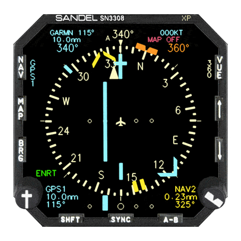
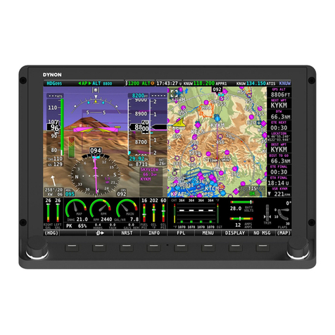
DisplayAreas
The
primary display
area shows either a 360-degree or a 70-degree
ARC view, as indicated by the white compass ring. The white airplane
represents the aircraft’s current position. The primary display area
may also depict the current GPS flight plan, airport, navaids,
intersections, airspace and/or Stormscope®data if the map feature
has been enabled. Several indicators (see below) are also presented
within the primary display area.
The
upper display
area presents data from the selected course
navigation instrument. The actual data displayed depends on the
navigation source (VOR/DME, GPS, or loran) but it will generally
include bearing, distance and ground-speed, if available. The upper
display area also includes information on the map status, WX-500
Stormscope®status (if installed), and an annunciation of whether the
VOR nav display is currently receiving either a localizer or a full ILS
(localizer/glideslope) signal.
2-1
2Display Overview
CHAPTER
Other manuals for SN3308
2
Table of contents
Other Sandel Avionic Display manuals