IFM Electronic dn1030 User manual

Installation instructions
AC/DC power supplies
single phase
Power Supply
DN1030
DN1031
7390798 / 00 08 / 2011
UK

2
Contents
1 Preliminary note���������������������������������������������������������������������������������������������������3
1�1 Notes on this document���������������������������������������������������������������������������������3
1�2 Symbols used ������������������������������������������������������������������������������������������������3
1�3 Warning signs used ���������������������������������������������������������������������������������������3
2 Safety instructions �����������������������������������������������������������������������������������������������4
2�1 General����������������������������������������������������������������������������������������������������������4
2�2 Installation and connection ����������������������������������������������������������������������������4
2�3 Tampering with the device �����������������������������������������������������������������������������4
3 Functions and features ����������������������������������������������������������������������������������������4
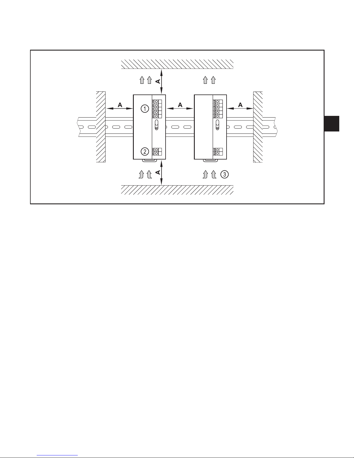
4 Installation������������������������������������������������������������������������������������������������������������5
4�1 Installation position of the device�������������������������������������������������������������������5
4�2 Place device onto the DIN rail �����������������������������������������������������������������������6
4�3 Remove the device����������������������������������������������������������������������������������������6
5 Electrical connection��������������������������������������������������������������������������������������������7
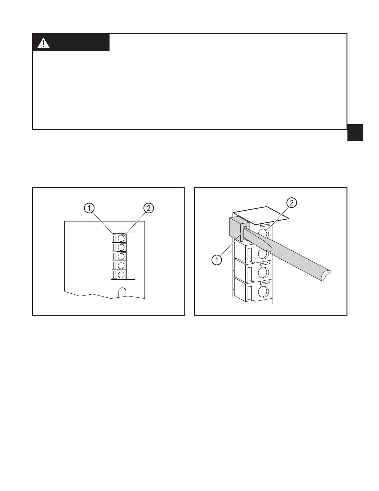
5�1 Using the spring terminals �����������������������������������������������������������������������������7
5�2 Core cross sections ���������������������������������������������������������������������������������������8
5�3 DC OK output ������������������������������������������������������������������������������������������������8
5�3�1 Switching characteristics ����������������������������������������������������������������������8
5�4 External fuse��������������������������������������������������������������������������������������������������9
5�5 Parallel connection ����������������������������������������������������������������������������������������9
6 Operating and display elements ������������������������������������������������������������������������10
6�1 LED states ���������������������������������������������������������������������������������������������������10
7 Operation�����������������������������������������������������������������������������������������������������������10
8 Technical data���������������������������������������������������������������������������������������������������� 11
8�1 Data sheets ������������������������������������������������������������������������������������������������� 11
9 Maintenance, repair and disposal���������������������������������������������������������������������� 11
10 Approvals/standards ���������������������������������������������������������������������������������������� 11

3
UK
1 Preliminary note
1.1 Notes on this document
This document applies to devices of the type "power supply" (art� no�: DN103x)�
It is part of the device and contains information about the correct handling of the
product�
This document is intended for qualified electricians� These specialists are people
who are qualified by their training and their experience to see and to avoid
possible hazards that may be caused during operation of the device�
►Read this document before using the device�
►Keep this document during the service life of the device�
1.2 Symbols used
►Instructions
> Reaction, result
[…] Designation of pushbuttons, buttons or indications
→Cross-reference
Important note
Non-compliance can result in malfunction or interference�
Information
Supplementary note
1.3 Warning signs used
WARNING
Warning of serious personal injury�
Death or serious irreversible injuries may result�
CAUTION
Warning of personal injury�
Slight reversible injuries may result�
NOTE
Warning of damage to property�

4
2 Safety instructions
2.1 General
►Observe these operating instructions�
►Adhere to the warning notes on the product�
Non-observance of the instructions, operation which is not in accordance with use
as prescribed below, wrong installation or incorrect handling can affect the safety
of operators and machinery�
2.2 Installation and connection
The device must only be installed, connected and put into operation by a qualified
electrician as the safe function of the device and machinery is only guaranteed
when installation is correctly carried out�
The installation and connection must comply with the applicable national and
international standards� Responsibility lies with the person installing the device�
2.3 Tampering with the device
Tampering with the device is not allowed and will lead to an exclusion of liability
and warranty� Tampering with the device can affect the safety of operators and
machinery�
►Do not open the device�
►Do not insert any objects into the device�
►Prevent metal foreign bodies from penetrating�
3 Functions and features
● The device is used for the regulated 24VDC voltage supply of industrial
controllers, sensors, actuators or measuring systems�
● It is intended for installation in a dry, closed environment (e�g� control cabinet)�
►Observe the connection values and the permissible environmental conditions
→devicelabelordatasheet.
WARNING
Do not use the device in applications where a malfunction of the device presents
a danger to people�

5
UK
4 Installation
4.1 Installation position of the device
1: DC output voltage top
2: AC input voltage bottom
3: Convection cooling
A: Free space for convection cooling
►Install the DIN rail for receiving the device horizontally�
► Keeptotheclearspaceforconvectioncooling(→datasheet).

6
4.2 Place device onto the DIN rail
1� Angle the device and hook it onto the upper edge of the DIN rail�
2� Push the device downwards and press to lock�
> The device audibly clips into place�
4.3 Remove the device
1� Pull the locking clip downwards using a screwdriver�
2� Lift the device and remove it from the DIN rail�

7
UK
5 Electrical connection
WARNING
Dangerous contact voltages� Electric shock possible in the case of contact�
►Disconnect the system from power before working with it�
►Protect the system against unintentional switch-on�
►Select the correct connecting cables for the load and the environmental
conditions�
►Use wire end ferrules for flexible connection wires�
►Connect the device according to the wiring arrangement�
Wiring→devicelabelordatasheet.
5.1 Using the spring terminals
1: Rectangular recess for locating the screwdriver
Blade width: max� 3 mm
2: Terminal opening
►Push the screwdriver gently into the rectangular recess (1)�
> The spring terminal is opened by the pressure�
►Insert the wire into the round terminal opening (2)�
►Remove the screwdriver�
> The spring terminal is closed� The wire is tightly clamped�

8
5.2 Core cross sections
Type of wire Max� core cross-section AWG
massive 1�5 mm² 16
flexible 1�5 mm² (with wire end ferrule) −
5.3 DC OK output
The DC OK output is a semiconductor output� It is used for switching signalling
and control devices�
ConnectionvaluesDCOKoutput→datasheet
5.3.1 Switching characteristics
DC OK output Operating mode DC output voltage
switched
(conducting) normal operation > 20 V
open
(not conducting)
overload
< 20 V
short circuit
overvoltage (external)
AC input voltage missing
internal device error

9
UK
5.4 External fuse
► ProtecttheACinputvoltagebymeansofcircuit-breakers(fuserate→device
label or data sheet)�
►Observe the national regulations�
5.5 Parallel connection
DN103x
DN103x
Block diagram
Connect maximum 2 units with the same article no� in parallel (e�g� 2 x
DN1030 or 2 x DN1031)�
The DC output voltages of the devices have to be identical�
►Check the DC output voltage of the devices using a voltmeter and adapt it by
meansofthepotentiometer(→6Operatinganddisplayelements).
WARNING
Caution during operation when switched on� Due to protection rating IP 20
contact with dangerous contact voltages is possible�
►The device must only be operated by a qualified electrician�

10
6 Operating and display elements
1: LED DC OK (green)
2: Potentiometer 24���28 V DC output voltage
3: Locking clip
6.1 LED states
DC OK (green) Operating mode DC output voltage
On normal operation > 20 V
Off
overload
< 20 V
short circuit
overvoltage (external)
AC input voltage missing
internal device error
7 Operation
CAUTION
Due to the internal heating there may be perceptible hot temperatures on the
device surface� Can cause burns�
►Do not touch the device during operation or immediately after it has been
switched off�

11
UK
8 Technical data
8.1 Data sheets
Data sheets can be found at:
www.ifm.com→Datasearchdirect:→DN103x
9 Maintenance, repair and disposal
The device is maintenance-free and does not contain any components that need
to be maintained by the user�
WARNING
Tampering with the device can affect the safety of operators and machinery� The
device must only be repaired by the manufacturer�
►Do not open the housing�
►In case of malfunction of the device or uncertainties contact the manufacturer�
►Dispose of the device in accordance with the national environmental
regulations�
10 Approvals/standards
Teststandardsandprovisions→datasheet.
The EC declaration of conformity and approvals can be found at:
www.ifm.com→Datasheetdirect:→DN103x→Approvals
This manual suits for next models
1
Table of contents
Other IFM Electronic Power Supply manuals
Popular Power Supply manuals by other brands

Phoenix Contact
Phoenix Contact TRIO-PS-2G/1AC/24DC/10/B+D datasheet

Elsner
Elsner KNX PS640+IP Installation and adjustment manual

Phoenix Contact
Phoenix Contact SHDSL-PROFIBUS user manual

L&L
L&L TLR01 installation instructions

Delta Electronics
Delta Electronics Delphi Q48DV datasheet

BEL
BEL TCP3500-1024G Installation instruction