IFM Electronic ecomat200 DN301 Series User manual

Installation instructions
AC/DC power supplies
single phase
Power supply
DN301x
7390729 / 00 02 / 2010
UK

2
Contents
1 Preliminary note���������������������������������������������������������������������������������������������������3
1�1 Notes on this document���������������������������������������������������������������������������������3
1�2 Symbols used ������������������������������������������������������������������������������������������������3
1�3 Warning signs used ���������������������������������������������������������������������������������������3
2 Safety instructions �����������������������������������������������������������������������������������������������4
2�1 General����������������������������������������������������������������������������������������������������������4
2�2 Installation and connection ����������������������������������������������������������������������������4
2�3 Tampering with the device �����������������������������������������������������������������������������4
3 Functions and features ����������������������������������������������������������������������������������������4
4 Installation������������������������������������������������������������������������������������������������������������5
4�1 Installation position of the device�������������������������������������������������������������������5
4�2 Place device onto the DIN rail �����������������������������������������������������������������������6
4�3 Remove the device����������������������������������������������������������������������������������������6
5 Electrical connection��������������������������������������������������������������������������������������������7
5�1 Core cross sections ���������������������������������������������������������������������������������������7
5�2 DC OK output ������������������������������������������������������������������������������������������������7
5�2�1 Switching characteristics ���������������������������������������������������������������������8
5�3 External fuse��������������������������������������������������������������������������������������������������8
5�4 Parallel connection ����������������������������������������������������������������������������������������8
6 Operating and display elements ��������������������������������������������������������������������������9
6�1 LED state�������������������������������������������������������������������������������������������������������9
7 Operation�����������������������������������������������������������������������������������������������������������10
8 Technical data����������������������������������������������������������������������������������������������������10
8�1 Data sheets �������������������������������������������������������������������������������������������������10
9 Maintenance, repair and disposal����������������������������������������������������������������������10
10 Approvals/standards ����������������������������������������������������������������������������������������10
3
UK
Preliminary note1
Notes on this document1.1
This document applies to devices of the type "power supply" (art� no�: DN301x)�
It is part of the device and contains information about the correct handling of the
product�
This document is intended for qualified electricians� These specialists are people
who are qualified by their training and their experience to see and to avoid
possible hazards that may be caused during operation of the device�
Read this document before using the device�►
Keep this document during the service life of the device�►
Symbols used1.2
►Instructions
> Reaction, result
[…] Designation of pushbuttons, buttons or indications
→Cross-reference
Important note
Non-compliance can result in malfunction or interference�
Information
Supplementary note
Warning signs used1.3
WARNING
Warning of serious personal injury�
Death or serious irreversible injuries may result�
CAUTION
Warning of personal injury�
Slight reversible injuries may result�
NOTE
Warning of damage to property�

4
Safety instructions2
General2.1
Observe these operating instructions�►
Adhere to the warning notes on the product�►
Non-observance of the instructions, operation which is not in accordance with use
as prescribed below, wrong installation or incorrect handling can affect the safety
of operators and machinery�
Installation and connection2.2
The device must only be installed, connected and put into operation by a qualified
electrician as the safe function of the device and machinery is only guaranteed
when installation is correctly carried out�
The installation and connection must comply with the applicable national and
international standards� Responsibility lies with the person installing the device�
Tampering with the device2.3
Tampering with the device is not allowed and will lead to an exclusion of liability
and warranty� Tampering with the device can affect the safety of operators and
machinery�
Do not open the device�►
Do not loosen or remove the screw connection on the housing�►
Do not insert any objects into the device�►
Prevent metal foreign bodies from penetrating�►
Functions and features3
The device is used for the regulated 24VDC voltage supply of industrial●
controllers, sensors, actuators or measuring systems�
It is intended for installation in a dry, closed environment (e�g� control cabinet)�●
Observe the connection values and the permissible environmental conditions►
→devicelabelordatasheet.
WARNING
Do not use the device in applications where a malfunction of the device presents
a danger to people�
5
UK
Installation4
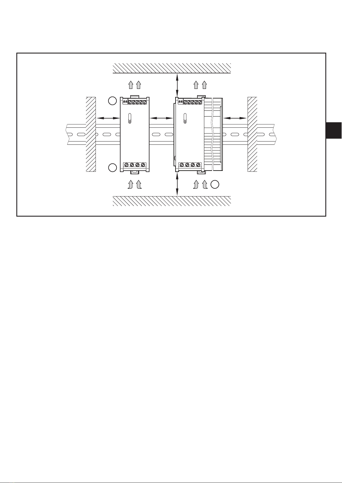
Installation position of the device4.1
�� �
��
DC output voltage top1:
AC input voltage bottom2:
Convection cooling3:
A: Free space for convection cooling
Install the DIN rail for receiving the device horizontally�►
Keeptotheclearspaceforconvectioncooling(→datasheet).►

6
Place device onto the DIN rail4.2
�
�
Angle the device and hook it onto the upper edge of the DIN rail�1�
Push the device downwards and press to lock�2�
The device audibly clips into place�>
Remove the device4.3
Press the locking clip downwards or alternatively use a screwdriver to pull it1�
downwards�
Lift the device and remove it from the DIN rail�2�

7
UK
Electrical connection5
WARNING
Dangerous contact voltages� Electric shock possible in the case of contact�
Disconnect the system from power before working with it�►
Protect the system against unintentional switch-on�►
Select the correct connection cables for the load and the environmental►
conditions�
Use wire end ferrules for flexible connection wires�►
Connect the protective wire to the earth terminal�►
Connect the device according to the wiring arrangement�►
Do not connect cables to the terminals without marking�
Tightening torque: 0�5���0�6 Nm (for all terminals)
Wiring→devicelabelordatasheet
Core cross sections5.1
Terminals Type of wire Core cross-section AWG
DC OK massive 0�14���1�5 mm² 26���16
flexible 0�25���1�5 mm² (with wire end ferrule) −
AC massive 0�2���6 mm² 24���10
flexible 0�25���4 mm² (with wire end ferrule) −
DC massive 0�2���6 mm² 24���10
flexible 0�25���4 mm² (with wire end ferrule) −
DC OK output5.2
The DC OK output is a volt-free relay output (normally open)� It is used for
switching signalling and control devices�
ConnectionvaluesDCOKoutput→datasheet
8
Switching characteristics5.2.1
DC OK output Operating mode DC output voltage
Relay energised
(NO closed) normal operation 24���28 V
Relay de-energised
(NC open)
overload < 20 V
short circuit < 3 V
overvoltage (external) > 32 V
AC input voltage missing 0 V
internal device error
External fuse5.3
ProtecttheACinputvoltagebymeansofcircuit-breakers(fuserate→device►
label or data sheet)�
Observe the national regulations�►
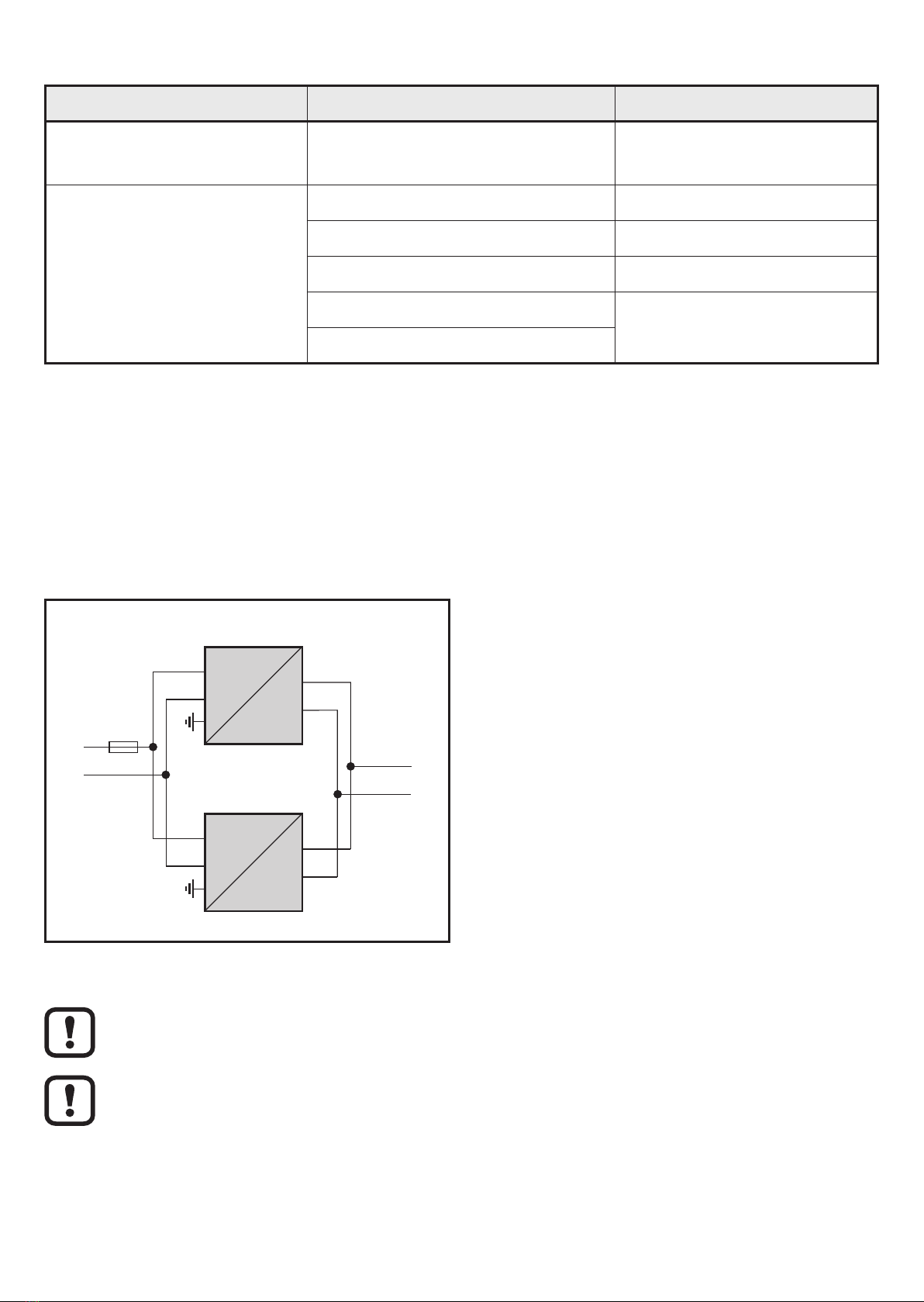
Parallel connection5.4
Block diagram
Connect maximum 2 units with the same article no� in parallel (e�g� 2 x
DN3011 or 2 x DN3012)�
The DC output voltages of the devices have to be identical�
Check the DC output voltage of the devices using a voltmeter and adapt it by►
meansofthepotentiometer(→6Operatinganddisplayelements).
9
UK
WARNING
Caution during operation when switched on� Due to protection rating IP 20
contact with dangerous contact voltages is possible�
The device must only be operated by a qualified electrician�►
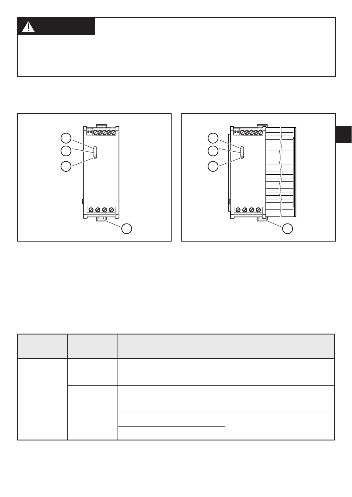
Operating and display elements6
Device width 50 mm Device width > 50 mm
LED DC OK (green)1:
LED DC ovl (red)2:
Potentiometer 24���28 V DC output voltage3:
Locking clip4:
LED state6.1
DC OK
(green)
DC ovl
(red)
Operating mode DC output voltage
On off normal operation 24���28 V
Off
on overload < 20 V
off
short circuit < 3 V
overvoltage (external) > 32 V
AC input voltage missing 0 V
internal device error
10
Operation7
CAUTION
Due to the internal heating there may be perceptible hot temperatures on the
device surface� Can cause burns�
Do not touch the device during operation or immediately after it has been►
switched off�
Technical data8
Data sheets8.1
Data sheets can be found at:
www.ifm.com→Datasearchdirect:→DN301x
Maintenance, repair and disposal9
The device is maintenance-free and does not contain any components that need
to be maintained by the user�
WARNING
Tampering with the device can affect the safety of operators and machinery� The
device must only be repaired by the manufacturer�
Do not open the housing�►
In case of malfunction of the device or uncertainties contact the manufacturer�►
Dispose of the device in accordance with the national environmental►
regulations�
Approvals/standards10
Teststandardsandprovisions→datasheet.
The EC declaration of conformity and approvals can be found at:
www.ifm.com→Datasheetdirect:→DN301x→Approvals
This manual suits for next models
1
Table of contents
Other IFM Electronic Power Supply manuals


