Power Supply Instruction Manual
Bedienungsanleitung für Stromversorgung
ifm electronic
Installation
Use DIN-rails according to EN 60715 or EN 50022 with a height of 7.5 or 15mm. Mounting
orientation must be output terminals on top and input terminals on the bottom. For other
orientations see datasheet. Do not obstruct air flow as the unit is convection cooled. Ventilation
grid must be kept free of any obstructions. The following installation clearances must be kept
when power supplies are permanently fully loaded:
Left / right: 0mm (or 15mm in case the adjacent device is a heat source)
40mm on top, 20mm on the bottom of the unit.
Installation
Geeignet für DIN-Schienen entsprechend EN 60715 oder EN 50022 mit einer Höhe von 7,5 oder
15mm. Der Einbau hat so zu erfolgen, dass sich die Eingangsklemmen unten und die
usgangsklemmen oben befinden. Für andere Einbaulagen siehe Datenblatt. Luftzirkulation nicht
behindern! Das Gerät ist für Konvektionskühlung ausgelegt. Es ist für ungehinderte Luftzirkulation
zu sorgen. Folgende Einbauabstände sind bei dauerhafter Volllast einzuhalten:
Links / rechts: 0mm (oder 15mm bei benachbarten Wärmequellen)
Oben: 40mm, unten 20mm vom Gerät.
Input Fuses
Internal input fuse included, not user accessible. The unit is tested and approved for branch
circuits up to 20A. An external protection is only required if the supplying branch has an ampacity
greater than this, however, in some countries local regulations might apply. Check local codes and
requirements. If an external fuse is necessary or utilized, minimum requirements need to be
considered to avoid nuisance tripping of the circuit breaker.
DN1023: A minimum value of 10A B- or 6A C-Characteristic breaker should be used.
Sicherungen am Eingang
Das Gerät besitzt eine Eingangssicherung, die nicht anwenderzugänglich ist. Das Gerät ist geprüft
und zugelassen zum Anschluss an Stromkreisen bis max. 20A. Ein zusätzlicher externer Schutz
ist nur erforderlich, wenn der Speisestromkreis mit einem höheren Wert abgesichert ist oder
nationale Richtlinien es vorschreiben. Falls ein externes Schutzelement verwendet wird, soll
dieses nicht kleiner als die folgenden Werte sein, um ein fehlerhaftes Auslösen zu vermeiden.
DN1023: 10A B- oder 6A C-Charakteristik.
Terminals and Wiring
Use appropriate copper cables that are designed for a minimum operating temperature of:
60°C for ambient temperatures up to 45°C,
75°C for ambient temperatures up to 60°C and
90°C for ambient temperatures up to 70°C.
Follow national installation codes and regulations! Ensure that all strands of a stranded wire enter
the terminal connection! Ferrules are allowed. Unused terminal must be closed.
Solid wire / Stranded wire / American wire gauge 0.5-6mm2/ 0.5-4mm2/ AWG20-10
Max. wire diameter: 2.8mm (including ferrules)
Wire stripping length 7mm / 0.28inch
Tightening torque 1Nm / 9lb.inch
Screw driver: 3.5mm slotted or Philips No 2
Anschlussklemmen und Verdrahtung
Verwenden Sie geeignete Kupferkabel, die mindestens für:
60°C bei einer Umgebungstemperatur bis zu 45°C,
75°C bei einer Umgebungstemperatur bis zu 60°C und
90°C bei einer Umgebungstemperatur bis zu 70°C zugelassen sind.
derendhülsen sind erlaubt. Nationale Bestimmungen und Installationsvorschriften beachten!
chten, dass keine einzelnen Drähte von Litzen abstehen. Nichtbenutzte Klemmen schließen.
Starrdraht / Litze / AWG 0,5-6mm2/ 0,5-4mm2/ AWG20-10
Maximaler Drahtdurchmesser: 2,8mm (inklusive Aderendhülsen)
Abisolierlänge 7mm / 0,28inch
Anzugsdrehmoment 1Nm / 9lb.inch
Schraubendreher: Schlitzschraubendreher 3,5mm oder Philips No 2
CE Marking
CE mark is in conformance with EMC directive and the low-voltage directive (LVD).
EMC Immunity: EN 61000-6-1, EN 61000-6-2
EMC Emission EN 61000-6-3, EN 61000-6-4, FCC Part 15 Class B
CE Kennzeichnung
Das CE Zeichen ist angebracht und erklärt die Erfüllung der EMV Richtlinie und der
Niederspannungsrichtlinie.
Störfestigkeit: EN 61000-6-1, EN 61000-6-2
Störaussendung: EN 61000-6-3, EN 61000-6-4, FCC Part 15 Klasse B
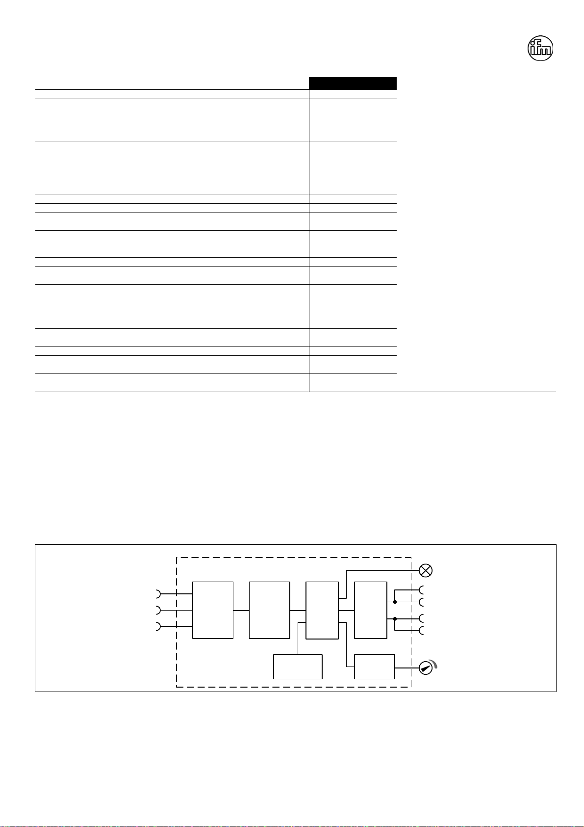
Output- and Overload Characteristic (see Fig. 3)
The units are overload, no-load, short-circuit proof. Above the rated output current, the output
voltage will decrease as a result of the output current limitation. The current flows continuously.
No hiccup or shut-down behaviour.
Ausgangs- und Überlastverhalten (siehe Bilder 3)
Die Geräte sind leerlauf-, überlast- und kurzschlussfest. Wird der Nennstrom überschritten, sinkt
die Spannung aufgrund der Strombegrenzungseigenschaft des Netzgerätes. Der Überlaststrom
fließt kontinuierlich (kein Hiccup).
Dielectric Strength (see Fig. 2)
The output voltage is floating and separated from the input according to SELV (IEC/EN 60950-1)
and PELV (EN 60204-1, EN 50178; IEC 62103, IEC 60364-4-41) requirements. Type and factory
tests are conducted by the manufacturer. Field tests may be conducted in the field using the
appropriate test equipment which applies the voltage with a slow ramp (2s up and 2s down).
Connect all phase-terminals together as well as all output poles before the test is conducted.
When testing, set the cut-off current settings to the value in the table below.
A B C
Type Test (60s) 2500Vac 4000Vac 2000Vac
Factory Test (5s) 2500Vac 2500Vac 500Vac
Field Test (5s) 2000Vac 2000Vac 500Vac
Cut-off current setting >4mA >4mA >1mA
Isolationsfestigkeit (siehe Bild 2)
Die Ausgangsspannung hat keinen Bezug zur Erde oder Schutzleiter und ist zum Eingang nach
den SELV (IEC/EN 60950-1) und PELV (EN 60204-1, EN 50178, IEC 62103, IEC 60364-4-41)
Standards getrennt. Typ- und Stückprüfungen werden beim Hersteller durchgeführt.Wieder-
holungsprüfungen dürfen mittels geeigneten Prüfgenerators mit langsam (2s) ansteigenden und
abfallenden Spannungsrampen in der Anwendung erfolgen. Vor den Tests sind alle Phasen wie
auch alle Ausgangspole miteinander zu verbinden. Während der Tests darf die Strom-
bschaltschwelle nicht kleiner als der in der Liste angegebene Wert sein.
A B C
Typprüfung (60s) 2500Vac 4000Vac 2000Vac
Stückprüfung (5s) 2500Vac 2500Vac 500Vac
Wiederholungsprüfung (5s) 2000Vac 2000Vac 500Vac
Strom- Abschaltschwelle >4mA >4mA >1mA
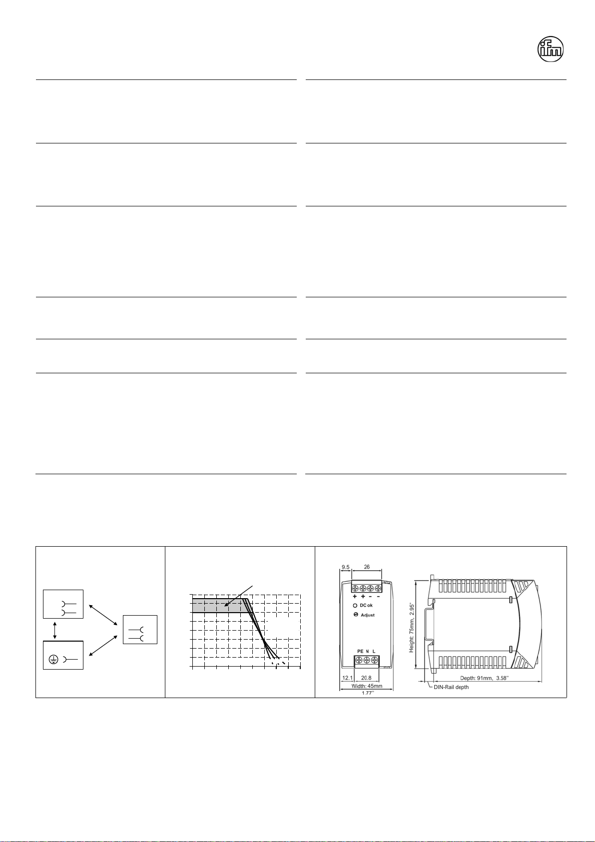
Fig. 2 / Bild 2
Isolation / Isolation Fig. 3 / Bild 3
Output Characteristic / Ausgangskennlinie, typ. Fig. 4 / Bild 4
Physical Dimensions / Abmessungen
A
C
N
L
Input
Earth, PE
Output
-
+
B
Output Voltage
00
2
4
6
16V
8
12
14
9
321 54
10
678
Adjustment
Range
Output Current
a) 100Vac
b) 120Vac
c) 230Vac
a
b
c
PU-377.010.22-10A