IFR 2026 User manual

MULTISOURCE GENERATOR
2026
Operating Manual
Document part no. 46892/439
Issue 3
6 April 2001

i
MULTISOURCE GENERATOR
2026
10 kHz to 2.4 GHz
Includes information on:
Option 1 −Three internal signal sources.
Option 3 −High-stability frequency standard.
Option 4 −Rear-panel connections.
This manual applies to instruments with software issues of 10.00 and higher.
© IFR Ltd. 2007
No part of this book may be reproduced or transmitted in
any form or by any means, electronic or mechanical,
including photocopying, or recorded by any information
storage or retrieval system, without permission in writing
by IFR Ltd.
Printed in the UK
Manual part no. 46892/439
Issue 3
6 April 2001

ii 46882/439
About this manual
This manual explains how to use the 2026 Multisource Generator.
Intended audience
Persons who have a need for accurately generated signals in the VHF and UHF spectrum.
It is assumed that the reader will be familiar with telecommunication terms used in modern
communication systems.
Structure
Chapter 1 Main features and performance data
Chapter 2 Installation details
Chapter 3 Local operation
Chapter 4 Source configuration, coupling and selected applications
Chapter 5 GPIB operation with keywords and sample programs
Chapter 6 Brief technical description
Chapter 7 Instructions for doing acceptance testing
Document conventions
The following conventions apply throughout this manual:
RF OUTPUT Titles marked on the instrument panel are shown in capital letters.
[SET UP] Key titles are as shown on the key-caps in square brackets.
[Carrier Freq] Soft key titles are shown in italics in square brackets; for example, [Carrier Freq]
means the soft key adjacent to the Carrier Freq title box at the side of the menu.
RF Level Messages on the display are shown in italic letters.
Associated publications
Other publications covering specific aspects of this equipment are:
Maintenance Manual (46882/295) Covers maintenance and repair.
Service Manual (46880/094) Consists of operating manual (this document) plus
maintenance manual.

46882/439 iii
Contents
PREFACE ...................................................................................................................................................... iv
Precautions ....................................................................................................................................................... v
Précautions ....................................................................................................................................................viii
Vorsichtsmaßnahmen......................................................................................................................................... x
Precauzioni .....................................................................................................................................................xii
Precauciones ....................................................................................................................................................xiv
Chapter 1 GENERAL INFORMATION .................................................................................................1-1
Chapter 2 INSTALLATION .....................................................................................................................2-1
Chapter 3 LOCAL OPERATION.............................................................................................................3-1
First-time use............................................................................................................................3-9
Individual source operation...................................................................................................3-17
Sweep.......................................................................................................................................3-27
Utilities.....................................................................................................................................3-31
Memory...................................................................................................................................3-45
Error messages .......................................................................................................................3-49
Chapter 4 SETUP.......................................................................................................................................4-1
Combiner setup ........................................................................................................................4-3
Coupling....................................................................................................................................4-5
Applications ..............................................................................................................................4-7
Chapter 5 REMOTE OPERATION.........................................................................................................5-1
Chapter 6 BRIEF TECHNICAL DESCRIPTION..................................................................................6-1
Chapter 7 ACCEPTANCE TESTING .....................................................................................................7-1
Test procedures.........................................................................................................................7-5
Acceptance test results tables................................................................................................7-31
INDEX .................................................................................................................................................... I-1

iv 46882/439
PREFACE
PATENT PROTECTION
The 2026 Multisource Generator is protected by the following patents:
EP 0322139
GB 2214012
US 4870384
EP 0125790
GB 2140232
US 4609881
46882/439 v
Precautions
These terms have specific meanings in this manual:
WARNING
information to prevent personal injury.
information to prevent damage to the equipment.
important general information.
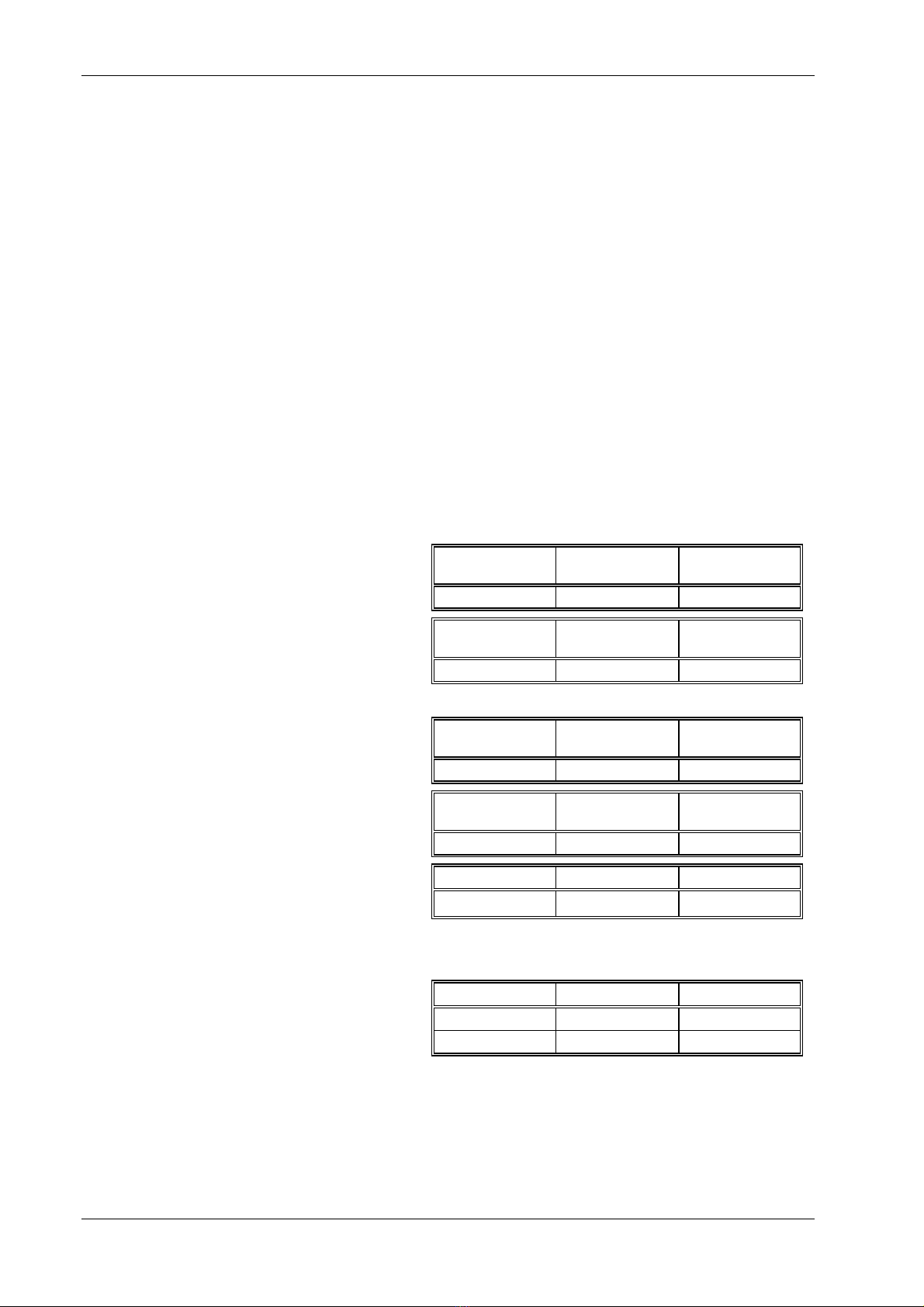
Hazard symbols
The meaning of hazard symbols appearing on the equipment is as follows:
Symbol Description
General hazard
Toxic hazard
General conditions of use
This product is designed and tested to comply with the requirements of IEC/EN61010-1 ‘Safety
requirements for electrical equipment for measurement, control and laboratory use’, for Class 1
portable equipment and is for use in a pollution degree 2 environment. The equipment is designed
to operate from an installation category 2 supply.
Equipment should be protected from the ingress of liquids and precipitation such as rain, snow,
etc. When moving the instrument from a cold to a hot environment, it is important to allow the
temperature of the instrument to stabilize before it is connected to the supply to avoid
condensation forming. The instrument must only be operated within the environmental conditions
specified in Chapter 1 ‘Performance data’ in the Operating Manual otherwise the protection
provided by the equipment may be impaired.
This product is not approved for use in hazardous atmospheres or medical applications. If the
equipment is to be used in a safety-related application, e.g. avionics or military applications, the
suitability of the product must be assessed and approved for use by a competent person.
WARNING
Electrical hazards (AC supply voltage)
This equipment conforms with IEC Safety Class I, meaning that it is provided with a protective
grounding lead. To maintain this protection the supply lead must always be connected to the
source of supply via a socket with a grounded contact.
Be aware that the supply filter contains capacitors that may remain charged after the equipment is
disconnected from the supply. Although the stored energy is within the approved safety
requirements, a slight shock may be felt if the plug pins are touched immediately after removal.
Do not remove covers, no user serviceable parts inside. See list of IFR Ltd International Service
Centers at rear of manual.
Fuses Note that the internal supply fuse is in series with the live conductor of the supply lead. If
connection is made to a 2-pin unpolarized supply socket, it is possible for the fuse to become
transposed to the neutral conductor, in which case, parts of the equipment could remain at supply
potential even after the fuse has ruptured.
PRECAUTIONS
vi 46882/439
WARNING
Fire hazard
Make sure that only fuses of the correct rating and type are used for replacement.
If an integrally fused plug is used on the supply lead, ensure that the fuse rating is commensurate
with the with current requirements of this equipment. See under 'Performance Data' in Chapter 1
for power requirements.
WARNING
Toxic hazards
Some of the components used in this equipment may include resins and other materials which give
off toxic fumes if incinerated. Take appropriate precautions, therefore, in the disposal of these
items.
WARNING
Beryllia
Beryllia (beryllium oxide) is used in the construction of some of the components in this
equipment. This material, if incorrectly handled, could cause a danger to health −refer to the
Maintenance part of the Service Manual for safe handling precautions.
WARNING
Beryllium copper
Some mechanical components within this instrument are manufactured from beryllium copper.
This is an alloy with a beryllium content of approximately 5%. It represents no risk in normal use.
The material should not be machined, welded or subjected to any process where heat is involved.
It must be disposed of as “special waste”.
It must NOT be disposed of by incineration.
WARNING
Heavy instrument
The weight of this instrument exceeds the 18 kg (40 lb) guideline for manual handling by a single
person. To avoid the risk of injury, an assessment should be carried out prior to handling which
takes account of the load, workplace environment and individual capability, in accordance with
European Directive 90/269/EEC and associated National Regulations.
WARNING
Tilt facility
When the instrument is in the tilt position, it is advisable, for stability reasons, not to stack other
instruments on top of it.
Static sensitive components
This equipment contains static sensitive components which may be damaged by handling −refer
to the Maintenance Manual for handling precautions.

PRECAUTIONS
46882/439 vii
Suitability for use
This equipment has been designed and manufactured by IFR Ltd. to provide RF signals from two
or three configurable sources. IFR Ltd. has no control over the use of this equipment and cannot
be held responsible for events arising from its use other than for its intended purpose.

PRECAUTIONS
viii 46882/439
Précautions
Les termes suivants ont, dans ce manuel, des significations particulières:
WARNING
contient des informations pour éviter toute blessure au personnel.
contient des informations pour éviter les dommages aux équipements.
contient d'importantes informations d'ordre général.
Symboles signalant un risque
La signification des symboles liés à cet équipement est la suivante:
Symbole Nature du risque
Risques généraux
Danger produits toxiques
Conditions générales d’utilisation
Ce produit a été conçu et testé pour être conforme aux exigences des normes CEI/EN61010-1
“Règles de sécurité pour appareils électriques de mesurage, de régulation et de laboratoire”, pour
des équipements Classe I portables et pour une utilisation dans un environnement de pollution de
niveau 2. Cet équipement est conçu pour fonctionner à partir d’une alimentation de catégorie II.
Cet équipement doit être protégé de l’introduction de liquides ainsi que des précipitations d’eau,
de neige, etc... Lorsqu’on transporte cet équipement d’un environnement chaud vers un
environnement froid, il est important de laisser l’équipement se stabiliser en température avant de
le connecter à une alimentation afin d’éviter toute formation de condensation. L’doit être utilisé
uniquement dans les conditions d’environnement spécifiées dans “Performance data” dans le
chapitre 1 du manuel d’utilisation, toute autre utilisation peut endommager les systèmes de
protection.
Ce produit n’est pas garanti pour fonctionner dans des atmosphères dangereuses ou pour un usage
médical. Si l'équipement doit être utilisé pour des applications en relation avec la sécurité, par
exemple des applications militaires ou aéronautiques, la compatibilité du produit doit être établie
et approuvée par une personne compétente.
WARNING
!
Securite electrique (tension d'alimentation alternative)
Cet appareil est protégé conformément à la norme CEI de sécurité class 1, c'est-à-dire que sa prise
secteur comporte un fil de protection à la terre. Pour maintenir cette protection, le cable
d'alimentation doit toujours être branché à la source d'alimentation par l'intermédiaire d'une prise
comportant une borne terre.
Notez que les filtres d'alimentation contiennent des condensateurs qui peuvent encore être chargés
lorsque l'appareil est débranché. Bien que l'énergie contenue soit conforme aux exigences de
sécurité, il est possible de ressentir un léger choc si l'on touche les bornes sitôt après
débranchement.
Ne pas enlever les capots, aucune pièce réparable ne se trouve à l'intérieur. Contacter un des
Centres de Maintenance Internationaux de IFR Ltd dans la liste jointe à la fin du manuel.
Fusibles Notez que le fusible d’alimentation interne est en série avec la phase du câble d’alimentation. Si la
prise d’alimentation comporte deux bornes non polarisées, il est possible de connecter le fusible au
neutre. Dans ce cas, certaines parties de l’appareil peuvent rester à un certain potentiel même
après coupure du fusible.
PRECAUTIONS
46882/439 ix
WARNING
Risque lie au feu
Lors du remplacement des fusibles vérifiez l'exactitude de leur type et de leur valeur.
Si le cable d'alimentation comporte une prise avec fusible intégré, assurez vous que sa valeur est
compatible avec les besoins en courant de l'appareil. Pour la consommation, reportez-vous au
chapitre 1 "Spécifications".
WARNING
Danger produits toxiques
Certains composants utilisés dans cet appareil peuvent contenir des résines et d'autres matières qui
dégagent des fumées toxiques lors de leur incinération. Les précautions d'usages doivent donc être
prises lorsqu'on se débarrasse de ce type de composant.
WARNING
Le Beryllia
Le Beryllia (oxyde de Beryllium) entre dans la composition de certains composants de cet
appareil. Cette matière peut représenter un danger pour la santé s'il elle n'est pas manipulée de
façon correcte −se référer à la partie "Maintenance" du "Manuel de Maintenance" pour les
précautions de manipulation.
WARNING
Bronze au béryllium
Dans cet équipement,certaines pièces mécaniques sont à base de bronze au béryllium. Il s'agit d'un
alliage dans lequel le pourcentage de béryllium ne dépasse pas 5%. Il ne présente aucun danger en
utilisation normale.
Toutefois, cet alliage ne doit pas être travaillé, soudé ou soumis à un processus qui implique
l'utilisation d'une source de chaleur.
En cas de destruction, il sera entreposé dans un container spécial. IL ne devra pas être détruit par
incinération.
WARNING
Instrument lourd
Le poids de cet appareil est supérieur à la limite de 18 kg (40 lb), fixée pour le transport par une
seule personne. Afin d’éviter tout risque de blessure, il est nécessaire de faire, avant le transport,
une évaluation de la charge, des contraintes de l’environnement et des capacités de l’individu, en
conformité avec la Directive Européenne 90/269/EEC ainsi que les recommandations Nationales
concernées.
WARNING
Position inclinée
Lorsque l'appareil est dans une position inclinée, il est recommandé, pour des raisons des stabilité,
de ne pas y empiler d'autres appareils.

PRECAUTIONS
x 46882/439
Vorsichtsmaßnahmen
Diese Hinweise haben eine bestimmte Bedeutung in diesem Handbuch:
WARNING
dienen zur Vermeidung von Verletzungsrisiken.
dienen dem Schutz der Geräte.
enthalten wichtige Informationen.
Gefahrensymbole
Die Gefahrensymbole auf den Geräten sind wie folgt:
Symbol Gefahrenart
Allgemeine Gefahr
Warnung vor giftigen Substanzen
Allgemeine Hinweise zur Verwendung
Dieses Produkt wurde entsprechend den Anforderungen von IEC/EN61010-1
“Sicherheitsanforderungen für elektrische Ausrüstung für Meßaufgaben, Steuerung und
Laborbedarf”, Klasse I, transportabel zur Verwendung in einer Grad 2 verunreinigten Umgebung,
entwickelt und getestet. Dieses Gerät ist für Netzversorgung Klasse II zugelassen.
Das Gerät sollte vor dem Eindringen von Flüssigkeiten sowie vor Regen, Schnee etc. geschützt
werden. Bei Standortänderung von kalter in wärmere Umgebung sollte das Gerät wegen der
Kondensation erst nach Anpassung an die wärmere Umgebung mit dem Netz verbunden werden.
Das Gerät darf nur in Umgebungsbedingungen wie in Kapitel 1 “Leistungsdaten (Performance
data)” der Bedienungsanleitung beschrieben, betrieben werden; ansonsten wird der vom Gerät
vorgesehene Schutz des Anwenders beeinträchtigt.
Dieses Produkt ist nicht für den Einsatz in gefährlicher Umgebung (z.B. Ex-Bereich) und für
medizinische Anwendungen geprüft. Sollte das Gerät für den Einsatz in sicherheitsrelevanten
Anwendungen wie z.B. im Flugverkehr oder bei militaerischen Anwendungen vorgesehen sein, so
ist dieser von einer für diesen Bereich zuständigen Person zu beurteilen und genehmigen.
WARNING
!
Elektrische Schläge (Wechselspannungsversorgung)
Das Gerät entspricht IEC Sicherheitsklasse 1 mit einem Schutzleiter nach Erde. Das Netzkabel
muß stets an eine Steckdose mit Erdkontakt angeschlossen werden.
Filterkondensatoren in der internen Spannungsversorgung können auch nach Unterbrechung der
Spannungszuführung noch geladen sein. Obwohl die darin gespeicherte Energie innerhalb der
Sicherheitsmargen liegt, kann ein leichter Spannungsschlag bei Berührung kurz nach der
Unterbrechung erfolgen.
Entfernen Sie keine Gehäuseabdeckungen, es befinden sich keine austauschbaren Teile im Gerät.
Eine Liste der IFR Servicestellen finden Sie auf der Rückseite des Handbuches.
Sicherungen
Die interne Sicherung in der Spannungszuführung ist in Reihe mit der spannungsführenden
Zuleitung geschaltet. Bei Verbindung mit einer zweiadrigen, nicht gepolten Steckdose kann die
Sicherung in der Masseleitung liegen, so daß auch bei geschmolzener Sicherung Geräteteile immer
noch auf Spannungspotential sind.

PRECAUTIONS
46882/439 xi
WARNING
Feuergefahr
Es dürfen nur Ersatzsicherungen vom gleichen Typ mit den korrekten Spezifikationen
entsprechend der Stromaufnahme des Gerätes verwendet werden. Siehe hierzu die Leistungsdaten
(Performance Data) in Kapitel 1.
WARNING
Warnung vor giftigen Substanzen
In einigen Bauelementen dieses Geräts können Epoxyharze oder andere Materialien enthalten sein,
die im Brandfall giftige Gase erzeugen. Bei der Entsorgung müssen deshalb entsprechende
Vorsichtsmaßnahmen getroffen werden.
WARNING
Beryllium Oxid
Beryllium Oxid wird in einigen Bauelementen verwendet.
Bei inkorrekter Handhabung kann dieses Material Gesundheitsschäden verursachen. Siehe hierzu
die Hinweise zur Handhabung im Service-Handbuch.
WARNING
Beryllium Kupfer
In diesem Gerät sind einige mechanische Komponenten aus Berylium Kupfer gefertigt. Dies ist
eine Verbindung welche aus einem Berylliumanteil von ca. 5 % besteht. Bei normaler
Verwendung besteht kein Gesundheitsrisiko.
Das Metall darf nicht bearbeitet, geschweißt oder sonstiger Wärmebehandlung ausgesetzt werden.
Es muß als Sondermüll entsorgt werden.
Es darf nicht durch Verbrennung entsorgt werden.
WARNING
Schweres Gerät
Das Gewicht dieses Geräts liegt über der 18 kg (40 lb) Grenze für Transport durch eine einzelne
Person. Zur Vermeidung von Verletzungen sollten vor einem Transport die Arbeitsumgebung und
die persönlichen Möglichkeiten im Verhältnis zur Last abgewogen werden, wie in der EU-
Regelung 90/269/EEC und nationalen Normen beschrieben.
WARNING
Schrägstellung
Bei Schrägstellung des Geräts sollten aus Stabilitätsgründen keine anderen Geräte darauf gestellt
werden.

PRECAUTIONS
xii 46882/439
Precauzioni
Questi termini vengono utilizzati in questo manuale con significati specifici:
WARNING
riportano informazioni atte ad evitare possibili pericoli alla persona.
riportano informazioni per evitare possibili pericoli all'apparecchiatura.
riportano importanti informazioni di carattere generale.
Simboli di pericolo
Significato dei simboli di pericolo utilizzati nell'apparato:
Simbolo Tipo di pericolo
Pericolo generico
Pericolo sostanze tossiche
Condizioni generali d'uso.
Questo prodotto è stato progettato e collaudato per rispondere ai requisiti della direttiva
IEC/EN61010-1 'Safety requirements for electrical equipment for measurement, control and
laboratory use' per apparati di classe I portatili e per l'uso in un ambiente inquinato di grado 2.
L'apparato è stato progettato per essere alimentato da un alimentatore di categoria II.
Lo strumento deve essere protetto dal possibile ingresso di liquidi quali, ad es., acqua, pioggia,
neve, ecc. Qualora lo strumento venga portato da un ambiente freddo ad uno caldo, è importante
lasciare che la temperatura all'interno dello strumento si stabilizzi prima di alimentarlo per evitare
formazione di condense. Lo strumento deve essere utilizzato esclusivamente nelle condizioni
ambientali descritte nel capitolo 1 'Performance Data' del manuale operativo, in caso contrario le
protezioni previste nello strumento potrebbero risultare non sufficienti.
Questo prodotto non è stato approvato per essere usato in ambienti pericolosi o applicazioni
medicali. Se lo strumento deve essere usato per applicazioni particolari collegate alla sicurezza
(per esempio applicazioni militari o avioniche),occorre che una persona o un istituto competente
ne certifichi l'uso.
WARNING
!
Pericoli da elettricità (alimentazione c.a.)
Quest' apparato è provvisto del collegamento di protezione di terra e rispetta le norme di sicurezza
IEC, classe 1. Per mantenere questa protezione è necessario che il cavo, la spina e la presa
d'alimentazione siano tutti provvisti di terra.
Il circuito d'alimentazione contiene dei filtri i cui condensatori possono restare carichi anche dopo
aver rimosso l'alimentazione. Sebbene l'energia immagazzinata è entro i limiti di sicurezza,
purtuttavia una leggera scossa può essere avvertita toccando i capi della spina subito dopo averla
rimossa.
Non rimuovere i coperchi, utilizzare solo parti di scorta originali. Vedi elenco internazionale dei
Centri di Assistenza in fondo al manuale.
Fusibili Notare che un fusibile è posto sul filo caldo del cavo di alimentazione. Qualora l’alimentazione
avvenga tramite due poli non polarizzati, è possibile che il fusibile vada a protezione del neutro
per cui anche in caso di una sua rottura, l’apparato potrebbe restare sotto tensione.

PRECAUTIONS
46882/439 xiii
WARNING
Pericolo d'incendio
Assicurarsi che, in caso di sostituzione, vengano utilizzati solo fusibili della portata e del tipo
prescritto.
Se viene usata una spina con fusibili, assicurarsi che questi siano di portata adeguata coi requisiti
di alimentazione richiesti dallo strumento. Tali requisiti sono riportati nel cap. 1 "Performance
data".
WARNING
Pericolo sostanze tossiche
Alcuni dei componenti usati in questo strumento possono contenere resine o altri materiali che, se
bruciati, possono emettere fumi tossici. Prendere quindi le opportune precauzioni nell'uso di tali
parti.
WARNING
Berillio
Berillio (ossido di berillio) è utilizzato nella costruzione di alcuni componenti di quest'apparato.
Questo materiale, se maneggiato non correttamente, può causare danni alla salute. Far riferimento
ai capitoli di manutenzione del Manuale di Servizio per le precauzioni richieste.
WARNING
Rame berillio
Alcuni componenti meccanici in questo strumento sono realizzati in rame berillio. Si tratta di una
lega con contenuto di berillio di circa il 5%, che non presenta alcun rischio in usi normali.
Questo materiale non deve essere lavorato, saldato o subire qualsiasi processo che coinvolge alte
temperature.
Deve essere eliminato come "rifiuto speciale". Non deve essere eliminato tramite "inceneritore".
WARNING
Strumento pesante
Il peso di questo strumento supera i 18 kg (40 lb) raccomandati come limite per il trasporto
manuale da parte di singola persona. Per evitare rischi di danni fisici è bene quindi considerare il
carico complessivo, le condizioni del trasporto e le capacità individuali in accordo con la direttiva
comunitaria 90/269/EEC e con eventuali regolamenti locali.
WARNING
Posizionamento inclinato
Quando lo strumento è in posizione inclinata è raccomandato, per motivi di stabilità, non
sovrapporre altri strumenti.
PRECAUTIONS
xiv 46882/439
Precauciones
Estos términos tienen significados específicos en este manual:
WARNING
contienen información referente a prevención de daños personales.
contienen información referente a prevención de daños en equipos.
contienen información general importante.
Símbolos de peligro
Los significados de los símbolos de peligro que aparecen en los equipos son los siguientes:
Símbolo Naturaleza del peligro
Peligro general
Aviso de toxicidad
Condiciones generales de uso
Este producto ha sido diseñado y probado para cumplir los requerimientos de la normativa
IEC/EN61010-1 "Requerimientos de la normativa para equipos eléctricos de medida, control y uso
en laboratorio", para equipos clase II portátiles y para uso en un ambiente con un grado de
contaminación 2. El equipo ha sido diseñado para funcionar sobre una instalación de alimentación
de categorías II.
Debe protegerse el equipo de la entrada de líquidos y precipitaciones como nieve, lluvia, etc.
Cuando se traslada el equipo de entorno frío a un entorno caliente, es importante aguardar la
estabilización el equipo para evitar la condensación. Sólo debe utilizarse el aparato en las
condiciones ambientales especificadas en el capítulo 1 "Especificaciones" o "Performance Data"
del Manual de Operación/Funcionamiento, en caso contrario la propia protección del equipo puede
resultar dañada.
Este producto no ha sido aprobado para su utilización en entornos peligrosos o en aplicaciones
médicas. Si se va a utilizar el equipo en una aplicación con implicaciones en cuanto a seguridad,
como por ejemplo aplicaciones de aviónica o militares, es preciso que un experto competente en
materia de seguridad apruebe su uso.
WARNING
!
Nivel peligroso de electricidad (tensión de red)
Este equipo cumple las normas IEC Seguridad Clase 1, lo que significa que va provisto de un
cable de protección de masa. Para mantener esta protección, el cable de alimentación de red debe
de conectarse siempre a una clavija con terminal de masa.
Tenga en cuenta que el filtro de red contiene condensadores que pueden almacenar carga una vez
desconectado el equipo. Aunque la energía almacenada está dentro de los requisitos de seguridad,
pudiera sentirse una ligera descarga al tocar la clavija de alimentación inmediatamente después de
su desconexión de red.
No quitar las tapas, en el interior no existen piezas reemplazables por el usuario. Vea la lista de
Centros de Servicios Internacionales en la parte trasera del manual.
Fusibles Se hace notar que el fusible de alimentación interno está enserie con el activo del cable de
alimentación a red. Si la clavija de alimentación de red cuenta con sólo dos terminales sin
polaridad, el fusible puede pasar a estar en serie con el neutro, en cuyo caso existen partes del
equipo que permanecerían a tensión de red incluso después de que el fusible haya fundido.
PRECAUTIONS
46882/439 xv
WARNING
Peligro de incendio
Asegúrese de utilizar sólo fusibles del tipo y valores especificados como recuesto.
Si se utiliza una clavija con fusible incorporado, asegúrese de que los valores del fusible
corresponden a los requeridos por el equipo. Ver sección de especificaciones del capítulo 1 para
comprobar los requisitos de alimentación.
WARNING
Aviso de toxicidad
Alguno de los componentes utilizados en este equipo pudieran incluir resinas u otro tipo de
materiales que al arder produjeran sustancias tóxicas, Por tanto, tome las debidas precauciones en
la manipulación de esas piezas.
WARNING
Berilio
Berilio (óxido de berilio) Este material es utilizado en la fabricación de alguno de los
componentes de este equipo.
Si se manipulase incorrectamente podria causar daños a la salud −En la sección de mantenimiento
y reparación encontrará normas de manejo de seguridad.
WARNING
Berilio-cobre
Algunos componentes mecánicos contenidos en este instrumento incorporan berilio-cobre en su
proceso de fabricación. Se trata de una aleación con un contenido aproximado de berilio del 5%,
lo que no representa ningún riesgo durante su uso normal.
El material no debe ser manipulado, soldado, ni sometido a ningún proceso que implique la
aplicación de calor.
Para su eliminación debe tratarse como un "residuo especial". El material NO DEBE eliminarse
mediante incineración.
WARNING
Instrumento pesado
El peso de este instrumento excede de los 18 kg (40 lb), lo que debe tenerse en cuenta si va ser
transportado manualmente por una sola persona. Para evitar el riesgo de lesiones, antes de mover
el equipo deberá evaluar la carga, el entorno de trabajo y la propia capacidad, de acuerdo con la
Directiva Europea 90/269/EEC y el Reglamento Nacional Asociado.
WARNING
Tener en cuenta con el equipo Inclinado
Si utiliza el equipo en posición inclinada, se recomienda, por razones de estabilidad, no apilar
otros equipos encima de él.

46882/439 1-1
Chapter 1
GENERAL INFORMATION
Contents Introduction....................................................................................................................................1-1
Main features .................................................................................................................................1-2
Operation ................................................................................................................................1-2
Display....................................................................................................................................1-2
Frequency selection ................................................................................................................1-2
Output.....................................................................................................................................1-2
Modulation..............................................................................................................................1-2
Incrementing...........................................................................................................................1-3
Frequency sweep ....................................................................................................................1-3
Memory...................................................................................................................................1-3
Programming ..........................................................................................................................1-3
Calibration data.......................................................................................................................1-3
Spectral purity.........................................................................................................................1-3
Calibration ..............................................................................................................................1-3
Performance data ...........................................................................................................................1-4
Versions, options and accessories..................................................................................................1-9
Introduction
The 2026 is a multisource signal generator offering as standard two signal sources in one
instrument. Up to three sources may be fitted, each of which is a fully functional modulated signal
generator. Each source can either be routed to its own individual RF output or switched to the
input of an RF combiner network before being fed to a separate combined RF output. All sources
cover the frequency range 10 kHz to 2.4 GHz. An additional RF input is provided to enable the
output from an external RF signal generator to be combined with the signals from up to two
internal sources.
Each signal source can be controlled independently in frequency and level, and each has its own
amplitude, frequency, phase, FSK and pulse modulation capability. All parameters can be entered
from the front-panel keyboard and a rotary control can be used to adjust most settings. The
instrument includes a GPIB interface which allows remote control of all standard signal generator
functions except the supply switch.
The instrument is provided with built-in tests specifically for use with two or three combined
sources such as for amplifier and receiver intermodulation tests and receiver selectivity tests.
The sources may be locked together, offset in frequency (additionally with a harmonic or
sub-harmonic relationship) as well as level.
Microprocessor control ensures that the instrument is flexible and easy to use and allows
programming by the General Purpose Interface Bus (GPIB) or RS-232 serial bus. The GPIB is
designed to IEEE Standard 488.2 and is a means of sending commands to an instrument, via a data
bus, from a remote controller or personal computer. The instrument can therefore be used
manually or as part of a fully automated test system.

GENERAL INFORMATION
1-2 46882/439
Main features
Operation
Selection of parameters on the screen may involve one or more of the numeric, hard or menu
selection keys or the rotary control knob. Parameters may be set to specific values by numeric key
entry, while values may be varied in steps of any size using the [Ø][×] keys or altered by
moving the control knob, set to a particular sensitivity.
Display The display is a dot matrix liquid crystal panel, with backlighting. Display contrast and brightness
may be varied to accommodate differing lighting conditions and the setting saved in memory.
Frequency selection
Carrier frequency is either selected directly via the keyboard or remotely via the interfaces.
Frequency resolution is 1 Hz across the complete frequency range of 10 kHz to 2.4 GHz. A series
of carrier frequencies can be stored in non-volatile memory for recall when required.
Output Peak RF output levels from each signal source of up to +24 dBm can be set up to 1.2 GHz
(+20 dBm up to 2.4 GHz) by direct keyboard entry with a resolution of 0.1 dB down to
−137 dBm. The peak output level from the combiner is +4 dBm up to 1.2 GHz (0 dBm up to
2.4 GHz). RF ON/OFF keys are provided to disable each individual output as well as the
combined output.
A choice of level units is available to the user and provision is made for the conversion of units
(for example, dBm to μV) by a simple keypress.
An electronic trip protects each independent signal source output against reverse power of up to
50 W. This prevents damage to output circuits when RF transmitter or DC power supply is
accidentally applied to an RF OUTPUT connector.
To facilitate testing of receiver squelch systems, an attenuator hold function allows control of the
RF output without introducing RF level drop-outs from the step attenuator.
Modulation
Comprehensive amplitude, frequency and phase modulations are available. Pulse modulation can
be applied to the carrier from an external pulse source. The instrument also produces FSK
modulated outputs. An internal modulation oscillator is provided, having a frequency range of
0.01 Hz to 20 kHz. Sine, triangle and square waveforms are available. The oscillator is capable of
generating one or two modulation tones simultaneously in one modulation channel. A BNC
connector on the front panel offers access to the internal LF signal as well as providing an input
for external modulation signals to be combined with the internal signals. These sources can be
combined to give a number of modulation modes. The pulse modulation can be used in
combination with the other forms of modulation.
The frequency modulation range provides a 1 dB bandwidth of typically 100 kHz and provides
FM deviation of 0 to 100 kHz. AC or DC coupled FM can be selected. Phase modulation is
provided with a 3 dB bandwidth of 10 kHz and deviation range of 0 to 10 radians.
Amplitude modulation with a 1 dB bandwidth of typically 30 kHz and with modulation depths of
up to 99.9% is available with a resolution of 0.1%. Pulse modulation is available as standard with
typical rise and fall times of less than 10 μs and 40 dB on/off ratio.
The instrument also accepts one or two logic level inputs to produce a 2-level or 4-level FSK
modulated output. The required FM deviation is set by keyboard entry.
The external input voltage required for specified modulation is 1 V RMS (1.414 V peak). To
accommodate other signal levels, Automatic Level Control (ALC) can be selected which provides
correctly calibrated modulation for inputs between 0.75 and 1.25 V RMS.
A modulation ON/OFF soft key simplifies the testing of signal-to noise-ratio.

GENERAL INFORMATION
46882/439 1-3
Incrementing
All major parameters can be incremented or decremented in step sizes entered via keyboard entry
or remotely. If no step size is entered for a parameter, the steps are preset to 1 kHz for carrier
frequency, 1 kHz for modulation oscillator, 1 kHz for FM deviation, 0.1% for AM depth, 0.01 rad
for ΦM and 1 dB for output level.
In addition, the rotary control knob can be used to vary the parameter with the sensitivity of the
knob being changed by means of the [×10] and [÷10] keys.
Control knob operation can be assigned for the adjustment of one parameter, while another
parameter is adjusted by the increment and decrement keys. By this means two parameters, for
example carrier frequency and RF level, can be adjusted simultaneously.
Frequency sweep
The sweep capability of the instrument allows comprehensive testing of systems. Four parameters
are used to specify sweep; start, stop, step size and time per step, all of which may be specified by
the user. The sweep can be paused at any time and the frequency and level manually altered.
During the sweep the RF level can be altered using the rotary control. Sweep triggering can be
single shot or continuous and can be initiated directly or on the detection of a trigger. The
triggering signal may either be programmed or from a TTL signal applied to the rear-panel
TRIGGER 1 input. When frequency coupling is enabled, the coupled sources will track with the
swept source.
Memory
The instrument provides both non-volatile and volatile memory for storing instrument settings.
The non-volatile memory provides 100 full instrument settings and 100 settings of carrier
frequency only. The volatile memory (RAM) also provides 100 instrument settings. Any one of
the non-volatile instrument settings can be selected as the power-up setting for the instrument.
Software protection
To prevent accidental interference with the contents of internal memories, internal data is
protected.
Programming
A GPIB interface is fitted so that all functions are controllable via the interface bus which is
designed to the IEEE Standard 488.2. The instrument can function both as talker and listener.
The instrument also has an RS-232 interface which uses the common GPIB command set to
control the instrument and also allow new software upgrades or applications to be downloaded
into the instrument.
Calibration data
All alignment data is digitally derived. Realignment can be undertaken, without removing covers,
by protected front-panel functions or via the GPIB interface.
Spectral purity
With an SSB phase noise performance of typically −121 dBc/Hz at 20 kHz offset from a 1 GHz
carrier, these instruments can be used for both in-channel and adjacent channel receiver
measurements. Harmonically-related signals and non-harmonics are typically better than −30 dBc
and −60 dBc respectively.
Calibration
This instrument has a recommended two-year calibration interval after which it should be returned
for recalibration (for addresses refer to ‘International Service Centers’ section at end of manual).
GENERAL INFORMATION
1-4 46882/439
Performance data
Carrier frequency
Range: 10 kHz to 2.4 GHz with a resolution of 1 Hz.
Accuracy: As frequency standard.
RF output
Range
Individual outputs: −137 dBm to +24 dBm
(output power above +20 dBm is uncalibrated for carrier frequencies
above 1.2 GHz).
Combined output: −137 dBm to +4 dBm (settable to +10 dBm)
(output power above 4 dBm is uncalibrated for carrier frequencies
above 1.2 GHz; output power is uncalibrated at all levels for carrier
frequencies below 1 MHz).
Maximum output is reduced by 5 dB when pulse modulation is
selected and/or by up to 6 dB when AM is selected, dependent upon
set AM depth.
Resolution: 0.1 dB.
RF level units: Units may be set to μV, mV, EMF or PD; dB relative to 1 μV, 1 mV,
EMF or PD; or dBm. Conversion between dB and linear units may be
achieved by pressing the appropriate units key (dB or V, mV, μV).
The output level can be normalized for 75 Ωoperation with an external
impedance converter (applies to all outputs simultaneously).
Accuracy:
Up to 1.2 GHz (over temperature range 17°C to 27°C):
RF level −127 dBm to
+6 dBm +6 dBm to
+24 dBm†
Individual outputs ±0.8 dB ±1.0 dB
RF level >−127 dBm to
+4 dBm‡
Combiner output ±1.0 dB
Up to 2.4 GHz (over temp range of 17°C to 27°C):
RF level −127 dBm to
+6 dBm +6 dBm to
+20 dBm
Individual outputs ±1.6 dB ±2.0 dB
RF level >−127 dBm to
0 dBm
Combiner output ±2.0 dB
Temp stability <1.2 GHz >1.2 GHz
dB/°C <±0.02 <±0.04
RF level tracking* (over a temperature range of +17°C to +27°C):
The relative level accuracy between any two or more combined signals
of equal amplitude is typically:
1 MHz−1.2 GHz 1.2 GHz−2.4 GHz
−18 to +4 dBm ±0.3 dB ±0.6 dB
<−18 dBm ±0.6 dB ±1.2 dB
Attenuator hold: Inhibits operation of the step attenuator from the level at which the key
is enabled. Usable for a level reduction of at least 10 dB. Typical
accuracy ±3 dB.
* This specification does not apply to external RF input signals to combiner.
†Level accuracy is unspecified below 100 kHz for levels greater than +6 dBm.
‡ Level accuracy is unspecified below 1 MHz.
Table of contents
Other IFR Inverter manuals

Popular Inverter manuals by other brands


SOLARMG
SOLARMG 1.5K user manual

EBARA
EBARA E-SPD Series Instruction and maintenance manual

Hitachi
Hitachi L100DN DeviceNet Series Addendum Read this first

Generac Power Systems
Generac Power Systems ECOGEN SERIES Installation guidelines

Clarke
Clarke Power CI400B Operating & maintenance instructions

Hitachi
Hitachi E43 Service manual