manuals.online logo
Brands
  1. Home
  2. •
  3. Brands
  4. •
  5. Tigo
  6. •
  7. Inverter
  8. •
  9. Tigo TSS-3PS User manual

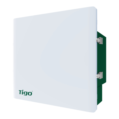
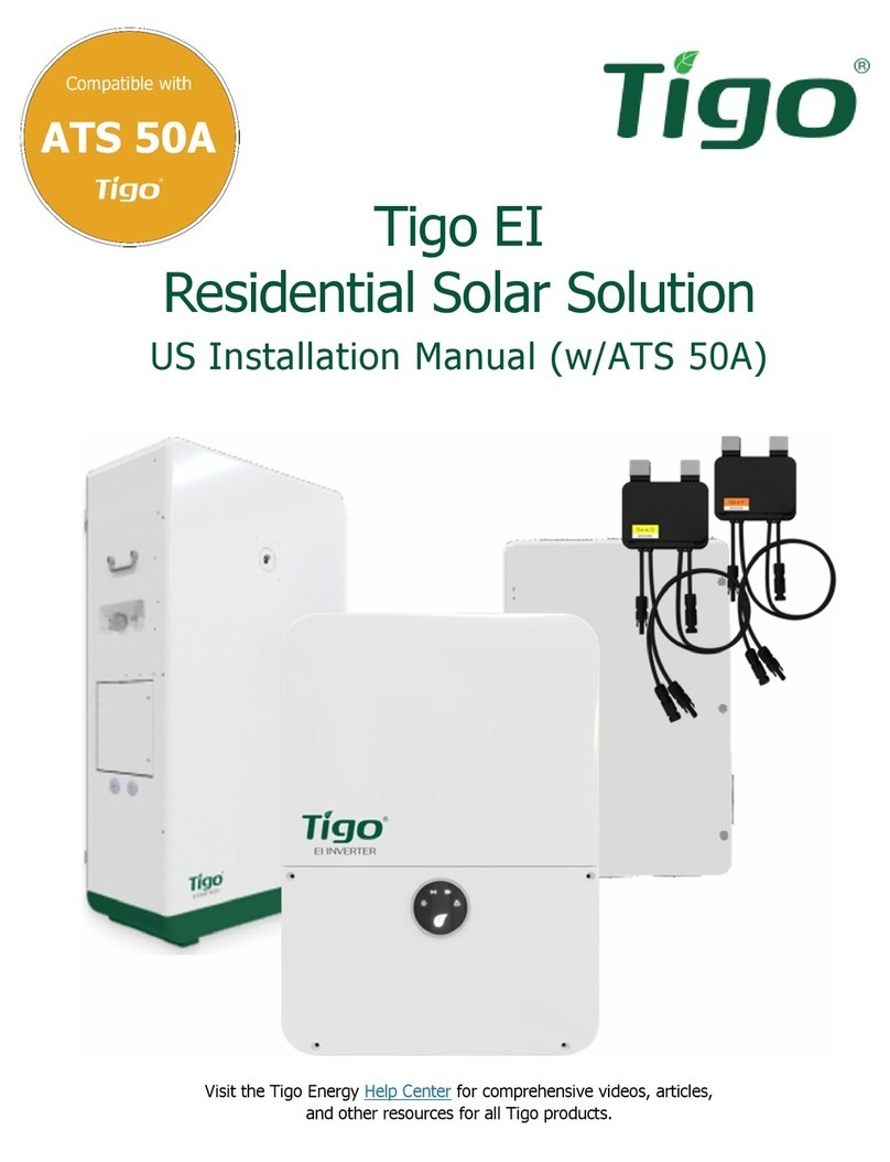
Tigo TSS-3PS User manual

EI Link - Three Phase
!1.1 Package Contents
Index Item Quantity
1 EI Link 1
2 EI Link bracket 1
3 Bridge bracket 1
4 6mm2ferrules 8
5 Flange nut 2
6 (Wall anchor, at washer, lag bolt) 2
7 16mm2grounding terminal 1
8 16mm2ferrules 10
9 Rubber plug 2
10 TAP 1
11 Waterproof RJ45 connector 3
12 Antenna (CCA) 1
13 Quick installation guide 1
1. General Information - Specications
ATTENTION - READ FIRST
!ATTENTION - Use the appropriate QSG's to perform the physical
installation of the EI system in the following order:
1. EI Battery
2. EI Inverter
3. EI Link
4. EI BMS
1. PV
2. PV (INV) (preinstalled)
3. EPS (INV)
4. Grid
9. Ethernet
10. TAP
11. COM (preinstalled)
12. E-stop
5. Grid (INV)
6. Load
7. Meter (preinstalled)
8. Antenna (preinstalled)
1.2 EI Link Overview
NG
EI Link
Grid
Meter
Main Panel Main Breaker
EI Inverter
Grid
EPS
Grid
NR
GS
T
Load
NR
S
T
N
G
EPS(Inv)
N
R
S
T
Grid(Inv)
R
GS
T
N
Quick Start Guide - TSS-3PS
Pg 1 of 3
1. This document is for general guidance only. Refer to the Energy Intelligence (EI) Inverter
Installation & Operations Manual for more detail.
2. Before installing the system, verify that the package contents are intact and complete as
per the packing list. Contact your dealer if there is equipment damage or missing
components.
PN: 002-00110-00 | REV 1.0 | Oct. 21, 2022
Load
Ethernet E-stop
COMTAP
AntennaMeterGrid
PV (INV)
1.3 Wiring Diagrams
2. Installation
Slide the EI Link on the EI Link
bracket below the EI Inverter
Remove the door and plastic cover of EI Link, slide it on to the
middle bracket and lock it with the M5 screw from the right side.
Inverter
bracket
Bridge
EI Link
bracket
EI Inverter
EI Link
21 3 4 5 6 7 8 9 10 11 12
2.1 Mount EI Link
2.2 Secure EI Link
3. Electrical Connections
3.1 EI Link Wiring
CAUTION - Check that all Disconnect switches are OFF before wiring. For personal safety always wear appropriate PPE.
!
1. Run the EPS and grid cables from inverter through
the strain reliefs.
2. Connect them to the EPS(INV) and Grid(INV)
terminals accordingly (refer to the back of the EI Link
door).
3. Attach the grounding wire to the grounding bar.
Torque to 1.5 NM.
3.1.1 Connect Inverter to EI Link
AC Connections DC Connections
EPS (INV) Grid (INV)
R (21) S (22) T (23) N (24) R (17) S (18) T (19) N (20) PE2
EI Link
EI Inverter
PV1+ PV1- PV2+ PV2-
EI BMS
BAT+ BAT-
PV1+
PV1-
PV2+
PV2-
BAT+
BAT-
PV PV(INV)
PV Array
PV1+ PV1-
PV1+
PV1-
EPS (INV)
Grid (INV)
EI Link - Three Phase
Quick Start Guide - TSS-3PS
Pg 2 of 3
1. Run the grid and load wires through the strain relief
into the EI Link.
2. Strip 12 mm off wire ends and crimp on 16mm2
ferrule.
3. Connect the wire ends into the appropriate GRID and
LOAD terminals. Torque to 1.5 NM.
4. Crimp the grounding cable with provided 16mm2
grounding terminal.
5. Connect grounding cable to ground bar and torque to
1.5 NM.
6. Terminate the opposite end of the grid and load cable
at the main service panel and backup panel with the
appropriate tools.
EI Link
EI Link
Grounding Cable
EI Inverter
TAP
3.1.2 GRID and Load
Load Grid
R (13) S (14) T (15) N (16) R (26) S (27) T (28) N (29) PE2
3.1.3 TS4
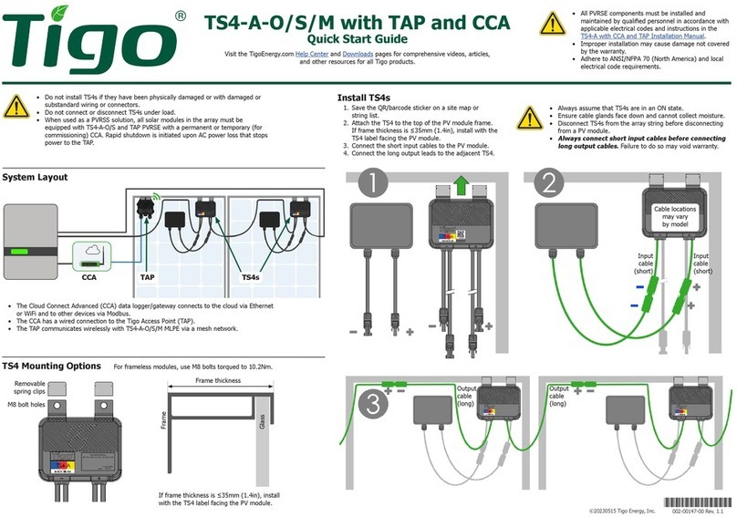
Scan here for the TS4 downloads
!
1. Install the TS4 module-level power electronics
(MLPE) on the back of the PV modules.
2. Connect the PV module to the TS4 input
conductors.
3. Connect the TS4 output conductors together to
form a string.
4. If using the TS4-A-F/TS4-A-2F, no additional steps
are necessary.
5. Remove each barcode sticker from the TS4-A-O
and place in the grid on the last page of this
document in the position and orientation of the
module as it is in the array. If using the TS4-A-F/
TS4-A-2F, this step is not necessary.
CAUTION - To prevent damage to the TS4, always connect PV modules to the TS4 input before connecting output
conductors in the string. Refer to the TS4 Installation Manuals for the TS4 installation requirements.
3.1.4 Connect PV Array
1. Run the PV wires through the strain relief into the EI
Link.
2. Strip 12 mm off wire ends and crimp them with the
provided 6mm2ferrules.
3. Press the wires into the appropriate PV + and PV -
terminals (Refer to the wiring diagram at the back of
the EI Link door.
PV
PV 1+ PV 1- PV 1+ PV 1- PV 2+ PV 2-
PV
3.1.6 Connect External Grounding
1. Connect the grounding cable from the
EI Inverter to the EI Link as shown.
2. Torque to 1.5 NM
3. Connect the grounding cable from the
EI BMS (when installed) to the EI Link
as shown.
4. Torque to 1.5 NM
3.1.5 TAP
1. Using CAT5/6, crimp the wires onto the RJ-45 male plug using the pin out diagram below.
2. Connect the other end of the wires to the corresponding terminals in the TAP as shown.
RJ45
Pin Wire color (T568B) Signal denition Function
1 White/Orange GND 12vDC- from CCA
2 Orange
3 White/Green VCC 12VDC + from CCA
4 Blue
5 White/Blue N/A Not in use
6 Green
7 White/Brown RS485B RS485 communication
with CCA
8 Brown RS485A
G1 G2 G2 G4
12345678
T568B
RJ-45 Male Plug
Load
Ethernet E-stop
COMTAP
AntennaMeter
Load Grid
PN: 002-00110-00 | REV 1.0 | Oct. 21, 2022
6. Your Customer Service Contact
Tigo Energy Italy
Srl Via Calamandrei 36 52025
Montevarchi Tuscany, Italy
Americas: +1 408 402 0802
International: 00800 2255 8446
https://support.tigoenergy.com/
EI Link - Three Phase
Quick Start Guide - TSS-3PS
Pg 3 of 3
4. Communication
5. BMS Installation
4.1 EI Link COM
Refer to the EI Inverter Quick Start Guide for the EI Link to Inverter communication connection. Connect the EI Link COM wire to the EI Inverter COM port.
Carefully screw WiFi antenna in the WiFi antenna port on the top left corner of the EI Link.
4.3 Connect the CCA Antenna
DC Switch
Note: You must make this connection before powering up the system!
Note: Proceed to the Battery Quick Start Guide Section 2.5 for the next part of the installation.
Battery QSG QR Code
CAN1 CAN2 DRM OFF
COM BMS CT
BAT
Load
Ethernet E-stop
COMTAP
AntennaMeter
EI LinkEI Inverter
EI Link EI Inverter
EI Inverter
EI Link
EI Battery
EI BMS
3.1.7 EI Link PV connections to EI Inverter
Load
Ethernet E-stop
COMTAP
AntennaMeterGrid
PV (INV)
CAN1 CAN2 DRM OFF
COM BMS CT
BAT
1. Connect EI Link PV (INV) preinstalled cables to EI Inverter PV1+/- and PV2+/-.
PN: 002-00110-00 | REV 1.0 | Oct. 21, 2022
Other Tigo Inverter manuals

Tigo TSI-7.6K-US User manual

Tigo

Tigo TSI-7.6K-US User manual

Tigo TSS-1PS User manual

Tigo

Tigo TSS-1PS User manual

Tigo ENERGY MODULE MAXIMIZER ES Series User guide

Tigo

Tigo ENERGY MODULE MAXIMIZER ES Series User guide

Tigo TS4-A-2F User manual

Tigo

Tigo TS4-A-2F User manual

Tigo EI User manual

Tigo

Tigo EI User manual

Tigo EI ATS 200A User manual

Tigo

Tigo EI ATS 200A User manual

Tigo TS4-A-O User manual

Tigo

Tigo TS4-A-O User manual

Tigo TSI-3K1D User manual

Tigo

Tigo TSI-3K1D User manual

Tigo EI User manual

Tigo

Tigo EI User manual

Tigo TSI-6K3DTSI-10K3D User manual

Tigo

Tigo TSI-6K3DTSI-10K3D User manual

Tigo EI User manual

Tigo

Tigo EI User manual

Tigo EI Inverter User manual

Tigo

Tigo EI Inverter User manual

Tigo TS4-F User manual

Tigo

Tigo TS4-F User manual

Popular Inverter manuals by other brands

Champion Global Power Equipment 201004 Operator's manual

Champion Global Power Equipment

Champion Global Power Equipment 201004 Operator's manual

SolaX Power BOX user manual

SolaX Power

SolaX Power BOX user manual

SDMO PRO 2000 Instruction and maintenance manual

SDMO

SDMO PRO 2000 Instruction and maintenance manual

Weco Multi Power 184 instruction manual

Weco

Weco Multi Power 184 instruction manual

Spectron SE1450 Operating and maintenance manual

Spectron

Spectron SE1450 Operating and maintenance manual

MULTIQUIP Power WHISPERWATT DCA-15SPX4 Operation and parts manual

MULTIQUIP

MULTIQUIP Power WHISPERWATT DCA-15SPX4 Operation and parts manual

Omron MX2 -  V1.0 quick guide

Omron

Omron MX2 - V1.0 quick guide

DK-Technologies PT5300 Guide to installation and operation

DK-Technologies

DK-Technologies PT5300 Guide to installation and operation

INVT BD-RH1 Series user manual

INVT

INVT BD-RH1 Series user manual

Sungrow SH8.0RS user manual

Sungrow

Sungrow SH8.0RS user manual

Qlima WDH JA 2921 operating manual

Qlima

Qlima WDH JA 2921 operating manual

MIOX RIO-S Series Installation, operation and maintenance manual

MIOX

MIOX RIO-S Series Installation, operation and maintenance manual

EINHELL BT-PG 3100/1 Original operating instructions

EINHELL

EINHELL BT-PG 3100/1 Original operating instructions

PAW SolexMega-Kaskade HZ Installation and commissioning instructions

PAW

PAW SolexMega-Kaskade HZ Installation and commissioning instructions

Alessi-Serie 1000i-12 owner's manual

Alessi-Serie

Alessi-Serie 1000i-12 owner's manual

Power One AURORA Installation and operator's manual

Power One

Power One AURORA Installation and operator's manual

Valterra Products Go Power! GP-SW1500TS user manual

Valterra Products

Valterra Products Go Power! GP-SW1500TS user manual

Hoymiles HMS-1600-4T Quick installation guide

Hoymiles

Hoymiles HMS-1600-4T Quick installation guide

manuals.online logo
manuals.online logoBrands
  • About & Mission
  • Contact us
  • Privacy Policy
  • Terms and Conditions

Copyright 2025 Manuals.Online. All Rights Reserved.