iGage iG9 User manual

1 iGage iG9 User Manual
iG9 with IMU tilt
iG9a without IMU tilt
GNSS RTK Receiver
with Internal 2-Watt UHF Radio,
4G Cell Modem
User Manual
Also see the Getting Started Guide for
your selected Field Software.
This manual is for use with iG9 and iG9a RTK GNSS receivers produced by iGage Mapping
Corporation.
Receivers purchased from other sources that appear to be similar will not match devices
provisioned by iGage.
The ‘iGx Download Tool’ supplied with iG receivers and available for download via the internet,
only works with receivers purchased from iGage. The download tool is not sold separately.
13 May 2021
iG9_UserManual_RevL_417.docx

2 iGage iG9 User Manual
Copyright, Control and Safety
Copyright © 2021 iGage Mapping Corporation. All rights reserved.
No part of this manual may be reproduced, transmitted, transcribed, stored in a retrieval system or
translated into any language or computer language, in any form or by any means, electronic,
mechanical, magnetic, optical, chemical, manual or otherwise, without the prior written permission
of iGage Mapping Corporation.
iGage and ‘iGage Mapping Corporation’ are Trademarks of iGage Mapping Corporation of Salt Lake
City Utah, USA.
All product and brand names mentioned in this publication are trademarks of their respective
holders.
GNSS Safety Warning
The iG9 GNSS receiver tracks and utilizes signals from many space-based satellite navigation
systems:
The Global Positioning System (GPS) is operated by the US Government which is solely responsible
for the accuracy and maintenance of the GPS network. Accuracy can also be affected by bad satellite
geometry and obstructions including buildings and tree canopy.
The GLONASS (GLObal NAvigation Satellite System), is a satellite navigation system operated by the
Russian Aerospace Defense Forces.
The Galileo System is the global navigation satellite system (GNSS) that is operated by the European
Union (EU) and European Space Agency (ESA)
BeiDou Navigation Satellite System (BDS) (also known as COMPASS or BeiDou-2) is operated by
CNSA (China National Space Administration.)
SBAS (Satellite Based Augmentation Services) including WAAS (USA), MSAS (Japan), EGNOS (Europe),
QZSS (Asia), and GAGAN (India) may also be utilized by the iG9 for carrier-phase corrections, in
addition to differential corrections.
iGage Mapping Corporation is not responsible for, nor warrants the viability of the space segment
portion of the GNSS system. The user is cautioned that they alone are responsible for determining
the application of the iG9 to their task at hand.
Any of the GNSS system components can fail at any time. Be prepared for down time and failures.
Do not use the iG9 receiver for any critical navigation purpose.
Export Controlled Device
The iG9 device should be considered to be an export-controlled device.
Because of the complex federal sanction regulations governing controlled countries, as well as the
severe civil and criminal penalties for sanction violations, you should not attempt to interpret export
licensing requirements or license exclusions for travel, or transactions with comprehensively
embargoed countries. Before shipping, providing or hand carrying iG9 devices out of the United
States, consult counsel who specializes in ITAR/DOD matters.
The following country list is not exhaustive:
Afghanistan, Balkans, Belarus, Burundi, Central African Republic, Cote d'Ivoire, Crimea Region of
Ukraine, Cuba, Cyprus, Democratic Republic of the Congo, Eritrea, Fiji, Haiti, Iran, Lebanon, Liberia,

iGage iG9 User Manual 3
Libya, Myanmar (formerly Burma), North Korea, Republic of the Sudan (Northern Sudan), Rwanda,
Somalia, South Sudan, Sri Lanka, Sudan, Syria, Ukraine, Venezuela, Vietnam, Yemen, Zimbabwe
The countries in bold face type are comprehensively embargoed. Do not transport an iG9 receiver
to one of these countries.
FCC Compliance
FCC Notice: iG9 and iG9a receivers comply with the limits for a Class B digital device, pursuant to the
Part 15 of the FCC rules when it is used in the Portable Mode.
FCC ID: SY4-A01020
Operation is subject to the following two conditions:
This device may not cause harmful interference.
This device must accept any interference received, including interference that may cause
undesired operation.
An FCC License is required to use the iG9 as a UHF Base in transmit mode.
See the section ‘Radio Notices’ on page 14.

4 iGage iG9 User Manual
Table of Contents
Copyright, Control and Safety......................... 2
GNSS Safety Warning........................................2
Export Controlled Device..................................2
FCC Compliance................................................3
Table of Contents .......................................... 4
Introduction .................................................. 6
iGage iG9, iG9a vs. CHC i90..............................6
About the iG9 GNSS Receiver ......................... 7
Front Panel........................................................7
Receiver Back and Bottom ...............................8
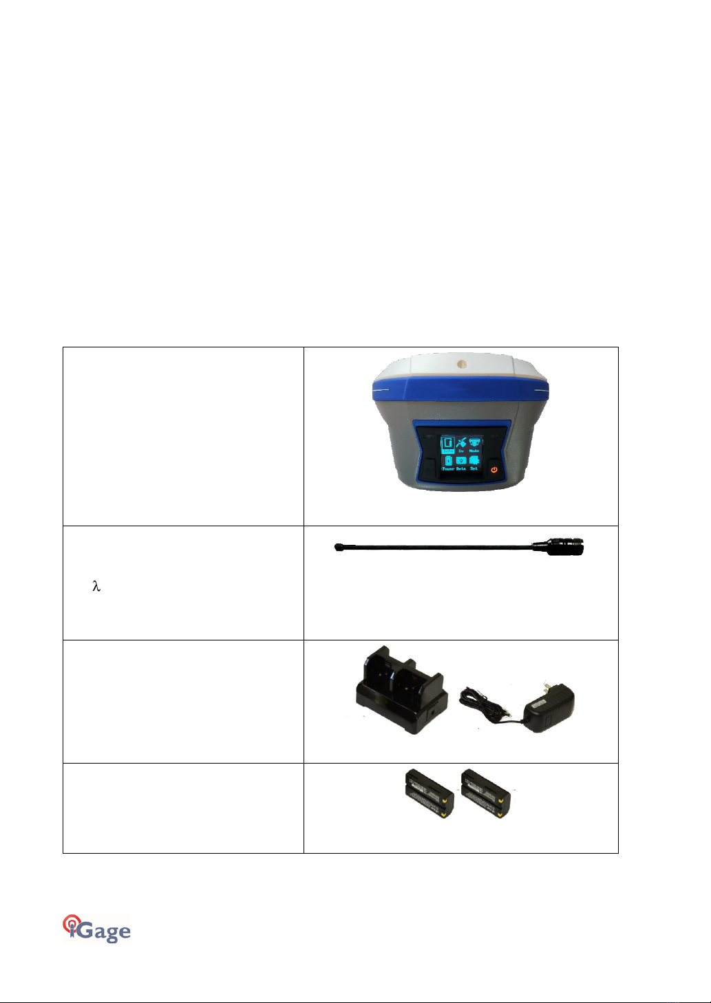
What’s in the Box......................................... 10
Optional Accessories ......................................12
iGA, High Gain UHF Antenna ........................12
iGR, 35-Watt Repeater / Transceiver ...........12
Safety Information....................................... 13
Use and Care .................................................13
Battery Warnings, Safety and Disposal..........13
Battery Charger...............................................14
Radio Notices ..................................................14
Bluetooth Radio.............................................15
UHF Radios.....................................................15
UHF Safety and General Information...........15
Medical Devices - Hearing Aids ....................15
Medical Devices - Pacemakers .....................15
Other Medical Devices..................................15
Blasting Caps and Blasting Areas..................16
FCC Licensing Information..............................16
Obtaining a New FCC License .......................16
Front Panel Operation.................................. 17
Main Menu ....................................................17
The Main Menu.............................................17
Front Panel: Info............................................18
Front Panel: Sv...............................................19
Front Panel: Receiver Mode .........................19
Front Panel: Power........................................21
Front Panel: Data...........................................21
Front Panel: Set.............................................21
Compatible Field Software ........................... 23
Using IMU Tilt Compensation ........................23
GeoMax X-PAD ..............................................23
Carlson SurvPC...............................................25
LandStar7.......................................................28
Best Practices for Extending UHF Radio Range
......................................................................... 30
Multiple Users on Same Radio Frequency .. 30
Base Output Power Setting.......................... 31
Bad Antennas................................................ 31
External Antenna Extension (Top of Pole
Extension)...................................................... 31
Loose TNC Antenna Connections................. 32
Configuring the iG9 Internal Cellular Modem 33
Optional: Configuring the APN and Cellular
Modem with the Web Interface .................. 33
Mission Planning..........................................35
Connecting the iG9 to a PC or Smartphone via
Wi-Fi............................................................37
Make sure Wi-Fi is Enabled.......................... 37
Wi-Fi turns off after 15-minutes to Save
Power ............................................................ 37
Connecting a Computer or Mobile Device.. 37
Programming iG9 Radio Frequencies and FCC
ID.................................................................40
Downloading, Processing and Archiving Static
Data.............................................................42
Installing the Download Tool......................... 42
Downloading Data from iG9 GNSS Receiver. 42
Starting the Download Tool........................... 43
Using the Download Tool............................... 43
Submitting an Occupation to OPUS .............. 44
Setting the Receiver Type.............................. 45
Viewing the Observation Log......................... 46
Trimming Occupation Files............................ 46
Performing Quality Control Checks............... 47
Advanced Download Settings........................ 47
Configuring the Download Tool................... 47
'Base Project Folder'..................................... 48
'Archive All Projects'..................................... 48
'GPS Mounts on Drive'.................................. 49
‘Update GPS Model’ ..................................... 49
‘Minimum File Size to Transfer’ ................... 49
‘Show UTC Time’........................................... 49
'Default HI' .................................................... 50
'Default Agency'............................................ 50
'Default Operator'......................................... 50
'Decimate OPUS Submission to ...'............... 50
'Your Email' ................................................... 51
'Show Advanced Settings' ............................ 51

iGage iG9 User Manual 5
‘PPP Service’ ..................................................51
Export 8.3 Filename ......................................51
Format Extended...........................................52
Utilities ............................................................52
“1. Undelete Occupations”...........................52
“2. CHCData RINEX Convertor”.....................52
“3. Mark One File Unread” ...........................53
“4. Mark All GPS Files Unread”.....................53
GPS Settings ....................................................53
GPS 'Settings' Tab ...........................................53
The ‘Log’ Tab...................................................53
OPUS: What is it?......................................... 54
OPUS-RS (Rapid Static)..................................54
OPUS-Projects................................................55
OPUS Error Messages and Failures................55
Interpreting OPUS Results..............................55
US Survey Feet vs. International Feet, Scale
Factors ...........................................................56
Getting ready to use OPUS.............................56
Using OPUS-Projects.......................................58
Best OPUS Practices for New and Experienced
Users........................................................... 59
The ‘OPUS Error Message’ Joke.....................59
#1 OPUS-RS is Dicey........................................59
#2 Only Some Submissions are being returned
by OPUS...........................................................59
#3 OPUS-RS is Very dependent on the
Number, Availability, Proximity, Distribution
and Quality of nearby CORS Stations.............59
#4 Daily vs. Hourly CORS Availability .............60
#5 Some areas of the United States effectively
ONLY have Daily Data .....................................61
#6 Offline CORS Stations ................................62
#7 NGS CORS Station Quality .........................62
#8 GPS Suitable Locations ..............................65
Best Case Scenario..........................................65
Worst Case Scenarios .....................................66
Semi-Trucks and Trains.................................66
Large Structures to the South.......................67
Huge Trees to the South...............................67
Huge Trees Overhead ...................................67
Large Reflective Surfaces Nearby.................68
Deep Canyons................................................68
Power Poles................................................... 69
#9 Optimizing Occupations in the Real-World
......................................................................... 69
Receiver Placement...................................... 69
Longer Observations..................................... 70
#10 Mission Planning..................................... 70
#11 Be Procedure Smart: avoid Blunders..... 71
Use a Fixed Height Tripod, Get the HI Correct!
....................................................................... 71
Rotate your Receiver Correctly.................... 72
Use the Correct Antenna Model.................. 72
Batteries In or Batteries Out? ...................... 73
#12 Why does Modern RTK work where OPUS
fails?................................................................ 73
Number of Satellites and Signals ................. 73
Baseline Distance.......................................... 73
#13 Fresnel Zone Considerations.................. 74
OPUS Best Practices Conclusion.................... 75
Troubleshooting the iG9 Receiver.................76
1. Receiver won’t turn on:............................ 76
2. Is the receiver tracking satellites? ........... 76
5. The receiver won’t mount as a Disk Drive.
....................................................................... 76
iG9 Serial and USB IO Port Definitions...........77
Serial IO Port Definition................................ 77
USB Port Definition....................................... 77
Upgrading Firmware ....................................78
Updating Main Board Firmware.................... 78
Updating OEM Firmware............................... 78
GNSS OEM Reset.......................................... 80
Web Interface Reset..................................... 80
Front Panel Reset.......................................... 80
iG9 Antenna Model......................................82
‘Slant Height’ to ‘Vertical Height’:.................83
Manually Converting Heights....................... 83
Examples....................................................... 83
Warranty .....................................................84
Exclusions...................................................... 84
RMA............................................................... 85

6 iGage iG9 User Manual
Introduction
Thank you very much for choosing to purchase and use an iG9 GNSS receiver from
iGage Mapping Corporation!
With a ground-breaking price, outstanding performance, field ready case and easy-
to-use features, we know that the iG9 receiver will be a valuable tool that will
quickly pay for itself.
This guide is designed to help you become familiar with your new equipment and successfully use it
in the field.
iGage Mapping Corporation
1545 South 1100 East Suite 1
Salt Lake City UT 84105 USA
+1-801-412-0011
email: info@igage.com
Your input is extremely valuable, and we will listen to your suggestions!
Software updates and news are available from:
www.iG9.xyz
Click on ‘Tools’ for firmware, FAQs and other iG9 information.
Don’t hesitate to call iGage for assistance deploying, using or updating your device. Remote
assistance is available.
iGage iG9, iG9a vs. CHC i90
The iGage iG9 is a variant of the CHC i90. There are many versions of the CHC i90 differing by
hardware options:
GNSS Antenna and Antenna Model
GNSS OEM Engine
Cell Phone Modem
Wi-Fi and Bluetooth Modules
IMU devices
UHF Radio Modules
All iGage iG9 receivers share the same electronic internals and GNSS Antenna. The iG9 has a
precision IMU Tilt Sensor, the iG9a does not have a IMU Tilt sensor.
Specific naming conventions:
Model Name: iG9, iG9a
Model Number: i90
Part Number: 118029040501020105
NGS Antenna Model: CHCI90 NONE
Because of the wide range of i90 possibilities, this User Manual is applicable only to the iG9 supplied
by iGage.

iGage iG9 User Manual 7
About the iG9 GNSS Receiver
The iG9 GNSS receiver incorporates a GNSS engine, GNSS antenna, internal Rx/Tx UHF radio, Cellular
modem, Bluetooth, Wi-Fi, and dual batteries in a ruggedized and miniature case that is easy to
deploy and use. All-in-One iG9 Base Rover kits include two receivers for use as Base and Rover.
Typically, the Rover will be an iG9 with IMU Tilt and the Base will be an iG9a without tilt sensors.
The bright LCD panel enables you to check satellite-tracking, internal battery charge status, Wi-Fi,
working mode, data logging status and basic receiver information. Bluetooth and Wi-Fi radios
provide cable-free communication between the receiver and a data collector / controller.
You can change many of the basic settings of the receiver with the two front panel buttons and LCD
panel. Additional configuration settings can be made via the web interface using Wi-Fi or with a
Bluetooth connected data collector.
Front Panel
The Front Panel has a bright LCD screen, two indicator LED’s and two pushbuttons.
Satellite LED
Indicates the number of satellites that the receiver is tracking:
When the receiver is searching and not tracking and
satellites it blinks Blue once every 5 seconds.
When the receiver is tracking and has a position the left
LED blinks Blue once for each tracked satellite.
Correction LED
Rover: FLOAT
Rover: Green
FIXED
Base: Amber Tx
Power / Enter
Button
Fn / Next Button
Blinks Amber when
recording data
recording raw
data)
Satellite LED (Blue)
LCD Screen

8 iGage iG9 User Manual
Correction LED
Base Operation: blinks amber as correction data is transmitted
Rover Operation: blinks amber when FLOAT or DGPS, green when
FIXed
LCD Screen
Displays status and configuration options, controlled by the two
pushbuttons
Fn Button
Move to the next line of the current menu
Move to the next character of a setting
Changes a setting or character after being selected by Enter
Power / Enter Button
Power (Red when turned on)
Press and Hold for 3-seconds to turn the receiver ON or OFF
Tap to accept a modified value: Enter
Receiver Back and Bottom
4G nano SIM Card
iG9 receivers have a NANO sized Sim Card slot. (NANO is the
smallest sized sim card.) Insert cards with gold contacts facing up
and the notch leading. The data modem is a 4G LTE modem and
should work with all providers, however the modem is NOT Verizon
certified.
Batteries
There are slots for two batteries. Push the retaining bars to the
side to release batteries, the battery will spring out. The batteries
2 Batteries
4G nano SIM Card
Serial / Power
TNC radio antenna
connector, recessed
for impact resistance.
Type-C USB
5/8” 11 TPI
Threaded Insert

iGage iG9 User Manual 9
are hot-swappable. The battery with the higher charge is always
used. Both batteries will run down simultaneously.
Battery Compartment
The battery compartment is sealed from the rest of the receiver.
Theoretically if you submerse the receiver with the door open, the
rest of the receiver will not be affected. However, the battery
contacts and the SIM card contacts will be damaged.
Serial / Power
7-pin LEMO connector supports RS-232 communication and
external power (9 to 28 VDC) input. Note, even if external power is
supplied at least one charged battery should be installed in the
receiver. (See “iG9 Serial and USB IO Port Definitions“ on page 77
for pinouts.)
Type C-USB
Standard USB-C connection to computer
When connected to a computer using a standard USB cable, the
iG9 will mount as an external disk drive on the attached computer:
no device drivers are required.

10 iGage iG9 User Manual
What’s in the Box
iG9 receivers are available in three standard configurations:
Base Rover Pair Kit: complete Base / Rover pair
Network Rover Kit: complete Network Rover, includes internal UHF radio
Base Fill Out Kit: fills out a Network Rover kit to a complete Base / Rover pair
We structure our kits so that you can purchase a Network Rover Kit, then add a Base Fill-Out Kit
later for the exact same price as purchasing a Base Rover pair.
iG9 receivers include a high-precision IMU tilt compensator, iG9a receivers do not include tilt. A
common kit includes an iG9 (with IMU Tilt) for the Rover and a iG9a (no IMU Tilt) for the Base.
In addition, any reasonable combination of receivers and accessories can be provided for specific
needs.
Depending on your purchased configuration you will receive different accessories with your iG9
GNSS receivers:
iG9 / iG9a GNSS Receiver
The iG9 receiver includes a state-of-the-
art GNSS engine, a 2-watt Tx/Rx UHF
radio, a 4G cellular GSM modem,
Bluetooth radio, and Display.
The Base and Rover are identical except
IMU Tilt is typically not purchased for
the Base.
Included with [Base and Rover]
UHF Antenna
PN: 0402 000 006
5/8 end-fed-dipole Antennas with TNC
Connector, one for each receiver.
Included with [Base and Rover]
Quad Battery Charger &
Wall Adapter
The Power Adapter can be used for the
battery charger or as an external power
source for iG9 Base with the serial cable.
Included with [Rover]
Lithium-Ion Batteries
High Capacity 3,400 mAH 7.4 V Lithium
Ion
Included with [Base and Rover]

iGage iG9 User Manual 11
External Heavy-Duty Power Cable
2.5 Meters long, connects to the Serial
connector on the bottom of the
receiver.
Provides extended power to an RTK
base.
Included with [Base]
SERIAL IO and Power Cable
Connects the GNSS head to a computer
serial port or an external UHF radio.
Can be used to provide external power
to the head.
Included with [Rover]
USB-C to USB-Female OTG
Used to extend internal memory for
huge occupation storage and to update
the receiver firmware with a thumbdrive
Included with [Rover]
USB 2.0 Cable - A-Male to Type-C
Used to connect the receiver to a PC and
download occupations from the internal
memory.
Included with [Rover]
Extension Pole
Raises the Base iG9 GNSS receiver above
a tribrach to allow the UHF antenna to
be connected to the receiver.
Included with [Base]
TNC Extension Cable
Allows you to elevate the Base UHF
radio antenna further above the ground,
greatly enhancing the radio range.
Included with [Base]
SIM CARD
We optionally include a non-activated
GSM SIM card withiG9 receivers. If you
are using the iG9 as a Network Rover
you can activate your own cellular data

12 iGage iG9 User Manual
service or iGage can optionally activate
this included card with annual service.
Included on request with
[Base and Rover]
This User Manual
We include a printed copy of this User
Manual with every iG9 kit.
Included with [every kit]
Field Ready Case
Sealed rugged hard cases with custom
foam inserts, and plenty of
compartments to protect your receiver
and accessories.
Included with [Base and Rover]
Optional Accessories
iGA, High Gain UHF Antenna
Extends UHF Radio range, excellent spare antenna in case the factory antenna is broken.
iGR, 35-Watt Repeater / Transceiver
Works as a remote repeater or cable connected high power radio.
Kit includes:
Radio, Power/Data Cable, 5-dBi Antenna, cable, 5/8” mount,
USB-to-Serial adapter, User Manual

iGage iG9 User Manual 13
Safety Information
Before you use your receiver, please make sure that you have read and understand the following
warnings and safety requirements.
An absence of specific alerts does not mean that there are no safety risks involved. Warning and
Caution information is intended to minimize the risk of personal injury and/or damage to the
equipment.
Use and Care
The iG9 receiver is a field ready instrument; however, it is also a delicate electronic instrument. Take
suitable care to avoid damage to the instrument.
Please avoid dropping the receiver directly onto concrete, it can modify the phase center of the
GNSS antenna.
Avoid storing the receiver at excessive temperatures (hot or cold) as it will damage the internal
batteries.
Avoid storing the batteries at temperatures less than -40° F (-40° C) and temperatures higher than
160°F (70°C) as it will permanently reduce the battery capacity and life
DO NOT leave the iG9 or accessories inside a vehicle in the summer. Temperatures higher than
160°F will permanently reduce battery capacity and battery life.
GNSS receivers and especially Lithium-Ion batteries are like puppies: In the summer if
you leave them in your vehicle with the windows rolled up, you will kill them.
Battery Warnings, Safety and Disposal
Figure 1 Lithium-Ion Batteries for iG9 receivers
The batteries are Lithium-Ion type cells.
WARNING - Do not damage the rechargeable Lithium-ion battery. A damaged battery can cause an
explosion or fire and can result in personal injury and property damage.
To prevent injury or damage:
Do not use or charge the battery if it appears to be discolored, warped, the case is bulging, or
leaking battery fluid.
Do not expose the battery to fire, high temperature, or direct sunlight.
Do not immerse the battery in water.
Do not store the battery inside a vehicle during hot weather.
Do not drop or puncture the battery.

14 iGage iG9 User Manual
Do not open the battery or short-circuit its contacts.
Do not charge the batteries in chargers other than the supplied charger or a direct
replacement.
Do not charge similar batteries in the supplied charger, even if they fit
WARNING - Avoid contact with the rechargeable Lithium-ion battery if it appears to be leaking. The
battery fluid is extremely corrosive and contact with it will result in personal injury and/or property
damage.
If battery fluid gets into your eyes, immediately rinse your eyes with clean water and seek medical
attention. Do not rub your eyes!
If battery fluid gets onto your skin or clothing, immediately use clean water to wash off the battery
fluid.
If you plan on running a Base receiver for an extended period, it is suggested that you use the
supplied auxiliary power connector to connect to an external 12-volt battery. Remember that the
receiver GNSS antennas were calibrated with two batteries inserted. The phase center may change
if you remove the batteries.
Please keep at least one charged battery in the head when using auxiliary power.
Fully charge the batteries using the supplied charger before first use. Batteries are shipped to you
fully discharged.
Battery Charger
The supplied battery charger will charge 4 batteries at once.
Plug the charger into the supplied wall transformer or use the optional alligator-clip cable to
connect to a 12 Volt battery.
The charger has a RED LED on each side to indicate that power is attached.
Next to each battery is a GREEN LED with the following meanings
GREEN LED
STATUS
Off
No Battery Inserted
Blinking
Battery Charging
ON Steady
Battery is fully
charged
It is best to remove batteries from the charger when they have completed charging.
Radio Notices
FCC Notice: iG9 GNSS receivers comply with the limits for a Class B digital device, pursuant to the
Part 15 of the FCC rules when it is used in the Portable Mode.

iGage iG9 User Manual 15
Operation is subject to the following two conditions:
This device may not cause harmful interference
this device must accept any interference received, including interference that may cause
undesired operation
FCC Compliance:
Function
FCC-ID
Module Type
iG9 Device
SY4-A01020
Assembly
Figure 2 FCC ID's for iG9 receiver’s internal radios.
Bluetooth Radio
Radiated output power from the internal Bluetooth radio is far below FCC radio frequency exposure
limits. The Bluetooth radio operates within guidelines for radio frequency safety standards and
recommendations, which reflect the consensus of the scientific community.
The level of energy emitted is far less than the electromagnetic energy emitted by wireless devices
such as mobile phones. However, the use of wireless radios may be restricted in some situations or
environments, such as on aircraft or near blasting areas.
UHF Radios
Every iG9 GNSS receiver includes a 2-watt Tx/Rx radio capable of broadcasting UHF radio
transmissions.
UHF Safety and General Information
When used in the transmitting mode, even though the broadcast power is relatively low, you should
take these additional precautions:
Medical Devices - Hearing Aids
Some digital wireless radios may interfere with some hearing aids. In the event of such interference,
you may want to consult your hearing aid manufacturer to discuss alternatives.
Medical Devices - Pacemakers
The Advanced Medical Technology Association recommends that a minimum separation of 6 inches
(15 cm) be maintained between a handheld wireless radio and a pacemaker. These
recommendations are consistent with the independent research by, and recommendations of the
U.S. Food and Drug Administration.
Persons with pacemakers should:
• ALWAYS keep the radio more than 6 inches (15 cm) from their pacemaker when the radio is
turned ON.
• Not carry the radio in the breast pocket.
• Turn the device OFF immediately if you have any reason to suspect that interference is taking
place.
Other Medical Devices
If you use any other personal medical device, consult the manufacturer of your device to determine
if it is adequately shielded from RF energy. Your physician may be able to assist you in obtaining this
information.

16 iGage iG9 User Manual
Blasting Caps and Blasting Areas
To avoid possible interference with blasting operations, turn off your radio when you are near
electrical blasting caps, in a blasting area, or in areas posted: “Turn off two-way radio.” Obey all
signs and instructions.
FCC Licensing Information
The iG9 includes transmit / receive UHF radios and require FCC licensure for transmit operation in
the United States. It is illegal to operate the iG9 device in Transmit mode (as a UHF Base) without a
valid FCC license at any output power, in any area, under any non-emergency condition.
This article describes the pitfalls of broadcasting without a license:
http://www.amerisurv.com/PDF/TheAmericanSurveyor_Silver-PirateSurveyors_Jan2014.pdf
If you did not have an FCC license when your receivers were shipped, a default frequency table may
have been installed on your receiver. Without an FCC license you may only receive transmissions on
these frequencies.
You may not legally use this product in a transmit application without:
Obtaining a valid FCC License.
Verifying the frequency tables match your license.
Adding your FCC ID to the internal radios so that they can properly broadcast your license
in Morse Code every 15 minutes.
Putting a label on the devices with your FCC ID.
Keeping a copy of your FCC License with the transmitting devices when they are in use as a
transmitter.
In January 2020, the ‘Preventing Illegal Radio Abuse Through Enforcement Act, or “PIRATE”
Act (S.1228)’ was signed raising the penalty for non-compliance to $100,000 per day with a
$2,000,000 maximum!
If you choose to operate the iG9 as a UHF Base without obtaining an FCC license, you do so at your
own risk.
Obtaining a New FCC License
If you don’t have an existing FCC license to transmit UHF corrections and you will be using your
receiver as a Base (no license is needed for Rover operation as it is receive-only) you will likely use a
‘Radio Licensing Company’ to obtain frequency coordination and submit an application to the FCC.
The entire FCC application process typically costs around $600 of which includes $125 Frequency
Coordination and $260 for the FCC filling fee. You may be asked these questions when applying for a
license:
Question
Answer
Frequency Requested
“Standard RTK GPS Pool”, Monitor: NO
Band
451-469, no splits
System
Conventional
Type
Base and Mobile Simplex FB.MO
Wattage
35 Watts Mobile; 35 Watts Base
Bandwidth
12.5 kHz
Interconnection
None
Emission Type
Digital Data
Location
The States where you might work or ‘USA’
Antenna Mounted On
Survey Tripod, not to exceed 20 feet
Emission Designator
9K75F1D

17 iGage iG9 User Manual
Front Panel Operation
You can configure your iG9 receiver:
from the front panel using the two-button interface
from a data collector connected by Bluetooth to the
receiver.
This section describes operation using the buttons from the front
panel interface.
Main Menu
After the iG9 starts, the Status Overview Menu will be shown
Clicking either button or will display the Main Menu:
You can move the current selection through each of the items ‘Info, Sv, Mode, Power, Data, Set’ by
clicking the Fn (Left) button:
Fn / Next
Once the desired item is selected, click the Enter (right) button:
Power / Enter
Some menu pages have too many lines to fit on the display, click the Fn / Next button to scroll down
through the additional lines.
The Main Menu
If the overview menu is shown, or the screen is blank:
click the Fn button to display the Main Menu:

18 iGage iG9 User Manual
Use the Fn button to move through:
Info General information on all operation modes
Sv Information on satellite tracking by constellation and signal
Mode Choose from common Base and Rover operation modes
Power Display battery and external power status
Data Configure raw data recording
Set Display brightness, standby, sleep; Wi-Fi, 4G Cellular, OEM board reset, Language
selection
When the desired item is selected, click the Power/Enter button to select.
Front Panel: Info
The Info screen shows:
Device Serial Number
Device Part Number, spread over 3 lines
Device Main Firmware
Registration Status
Operation Mode: Base / Rover
UHF Radio Channel / Frequency
UHF Radio Protocol
UHR Radio Baud Rate
Static Recording: On / Off
Static Sample Interval: default 1 Sec
Static Filetype: HCN / RINEX
Recording Elevation Mask: default 10 degrees
RTK Differential Age
Network Connection Information
4G IMEI number
These items are spread over four screens, use the Fn button to move through each of the screens.
Click on the Fn button again to return to the main menu.

iGage iG9 User Manual 19
Front Panel: Sv
The Sv screen shows:
Total number of Satellites (Sv’s) Used / Tracked
GPS number of Satellites (Sv’s) Used / Tracked
BDS number of Satellites (Sv’s) Used / Tracked
GLO number of Satellites (Sv’s) Used / Tracked
GAL number of Satellites (Sv’s) Used / Tracked
Click the Fn button to display status for:
GPS L1, L2, L5
BDS B1, B2, B3
Click the Fn button to display status for:
GLO L1, L2, L3
GAL L1, L2, L3
Click on the Fn button again to return to the main menu.
Front Panel: Receiver Mode
The Mode screen allows selection of the receiver operation mode:
Base External UHF
Base Internal UHF
Base APIS
Base External UHF & APIS
Rover APIS
Rover UHF
Rover NTRIP
(Back)
Use the Fn button to move down to the desired mode to modify. Then click Enter to select. Each
mode has questions appropriate to the specific mode.
Note that if you select any of the Base modes, the receiver always does a ‘Read GPS’ and sets the
Base position to the current Autonomous or SBAS/WAAS value.
Mode Selection Descriptions:
Base External UHF
Format sCMRx, RTCM2.3, RTCM3, RTCM3.2, RTD, CMR, CMR+
OK
Cancel

20 iGage iG9 User Manual
Base Internal UHF
Protocol 2AS, CHC, Transparent, TT450S
Channel 1 through ..
Baud 19200, 9600, 4800 (depends on Protocol)
Power 0.5W, 1W, 2W
Format sCMRx, RTCM2.3, RTCM3, RTCM3.2, RTD, CMR, CMR+
OK
Cancel
Base APIS
Format sCMRx, RTCM2.3, RTCM3, RTCM3.2, RTD, CMR, CMR+
IP: select from common or custom
Port: 9901, 9902 .. 9920
OK
Cancel
Base External UHF & APIS
Format sCMRx, RTCM2.3, RTCM3, RTCM3.2, RTD, CMR, CMR+
IP: select from common or custom
Port: 9901, 9902 .. 9920
OK
Cancel
Rover APIS
Base ID: (enter base SN)
IP: select from common or custom
Port: 9901, 9902 .. 9920
OK
Cancel
Rover UHF
Protocol 2AS, CHC, Transparent, TT450S
Channel 1 through ..
Baud 19200, 9600, 4800 (depends on Protocol)
OK
Cancel
Rover NTRIP
Status Not Logging in
OK (click on OK to select the last used NTRIP or DIP connection)
Cancel
This manual suits for next models
1
Table of contents
Other iGage Receiver manuals