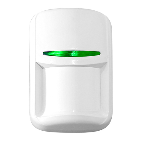
IGD TOC-750 Series User manual

Doc Ref: SL-068 v1.35 pg 1
TOC-750 SERIES
2-WIRE
DETECTOR NODES
&
STATUS INDICATORS
O p e r a t i o n a n d M a i n t e n a n c e
V 1 . 3 5
Document Ref: SL-068 v1.35
Operation Manual
TOC-750 Annunciator
FS646773 EMS696504
Triton House
Crosby Street
Stockport
SK2 6SH
internationalgasdetectors.com
+44 (0)161 483 1415
/international-gas-detectors-ltd
@

Doc Ref: SL-068 v1.35 pg 2
Index
Typical Models Covered By This Manual
Physical and Mounting Details
Module PCB Features
Connection Possibilities
Interconnecting Modules on a Data Highway
Relay Output
Solid State Output
Digital Input
4-20mA Inputs
Pellistor (Catalytic) Flammable Gas Detector Interface
Module Indications
Assigning Addresses
Local Sensor Zero and Calibration Required Equipment
Detector Zero Sequence
Detector Calibration Sequence
Reset to Defaults
CE Declaration
1
2
3
4
5
6
7
8
9
10
11
12
13
14
15
16
17
Gas detection systems must be correctly specified, installed and maintained in order to be effective.
Anyone undertaking elements of this work should have access to the necessary equipment and be able
to demonstrate competence. This will usually mean having passed a training competency course.
International Gas Detectors run training courses for safety survey, specification , installation and
service aspects of hazardous gas detection systems. In addition IGD can supply test equipment and
calibration gases necessary to undertake this work.
Please note the following points
1. A zero grade gas usually instrument air or Nitrogen and a suitable calibration gas mixture is required.
2. The correct gas adaptors must be used to apply gases to detectors when zeroing and calibrating.
Incorrect application of gases can affect calibration results
3. Use equipment and gases traceable to a national standard. Any calibration will only be as good as
the equipment and materials used.
4. IGD supply fixed flow regulators for use with IGD calibration gas bottles which supplies gas at
0.5L/Min
5. Refer to 2-Wire Gas Detection Systems Installers Guide before installation.
Important Notes

Doc Ref: SL-068 v1.35 pg 3
Typical Models Covered By This Manual
TOC-750 Series Hazardous Gas detectors can be supplied in a number of formats. Some
typical models are indicated in the diagram below. All 750 Series detectors and annunciators
use a common ‘module’ PCB as indicated below to interface between the detector or interface
and the control panel using IGD’s Sentinel+ 2-Wire protocol. A single 2-Wire ‘Highway’ can
support up to 32 devices interfaced using the ‘module’ PCB. Highways can be up to 1000M long
depending on cable size and detector types.
TOC-750 Room Status Indicator
TOC-750 Annunciator
With MK7 Gas Detector
TOC-750 Series Safe Area
Gas Detector
TOC-750 ATEX Hazardous Area
Gas Detector
2 Core Cable Highway For
Power and Communication
Between Module PCB’s
and Control Panel

Doc Ref: SL-068 v1.35 pg 4
Mounting Details and Dimensions Safe Area Versions
Mounting Details and Dimensions ATEX Versions
172
158
76
48
43
86
98 18
5
20mm Entries Top, Bottom & Either Side
Note TOC-750-AN3 Shown
145.0
126.0 128.5
COVER SECURING SCREW
M20 x 1.5
40.0
25.0
Ø7.0
EXTERNAL EARTH
MKIII FLAMMABLE
GAS DETECTOR
SHOWN
40.0
Ø110
128.0
The ATEX version uses IGD’s JB3 series ATEX EXD terminal enclosure. Please note that cable
glanding and sealing must conform to ATEX requirements which is more fully described in the
ATEX JB3 manual.
127.0

Doc Ref: SL-068 v1.35 pg 5
Module PCB Features
The following diagram indicates features available on the TOC-750 ‘module’ PCB. Please note
that failure to observe and make correct connections or exceed ratings may result in damage to
the PCB.
Ribbon Cable Connection For TOC-750
Annunciator Display and Options
Local LED Indications
And Up/Down Interface Buttons
Pellistor (Catalytic)
Flammable Gas
Detector Interface
Suitable for IGD
Types MK3, MK6, MK7
2-Wire Highway
Connection
To Next Device
Multi-Function I/O Port 1
Solid State Output or
4-20mA Input or
TOC-10 IP or Gas Meter
Multi-Function I/O Port 2
Solid State Output or
4-20mA Input or
TOC-10 IP or Gas Meter
Connection Point For
IGD Infra-Red, Toxic, PID
or Oxygen Gas Detectors
2-Wire Highway
Connection
To Next Device
P
Y
W
SPCO Relay
Output
DVM Test Point + DVM Test Point -
Housing
Sealing
Environment
Temperature
Voltage
Communication
Relay
Digital Output
Digital Input
Analogue I/P
Pellistor Port
Sounder
Display
Comm Port
1
2
3
4
5
6
7
TOC-750 Series ABS or Copper Free Aluminium For ATEX Versions
IP65 (using suitable glanding & splash guard) for TOC-750, IP68 for ATEX Versions
0 -95% RH Non Condensing
0-55 Deg C
12-28V DC
IGD 2-Wire Highway Operating IGD Sentinel+ Protocol Using 2 Core Screened Cable
Not Polarity Dependant
5A Non Inductive Loads 230V AC
24V DC 100mA Combined For Both Outputs Typically for LED Beacon Sounders
Suitable for use with TOC-10 Link Function, switch/call point, totalising count
4-20mA, selectable range, units and tag information
Option to Interface to MK3, MK6 or MK7 Pellistors
85dB (Option for TOC-750 Annunciators)
2 x 8 Programmable LCD with RGB Backlight (Option for TOC-750 Annunciators)
Supports IGD Infra-Red, PID, Toxic and Oxygen Gas Detectors
Module PCB Basic Interface Specifications
2
7
5
6
4
3 3
11

Doc Ref: SL-068 v1.35 pg 6
Connection Possabilities
The 750 Series Module PCB Operates as an Interface ‘Hub’ on the Addressable 2-Wire Highway.
The Diagram Below Shows a Typical Set of Connection Possibilities
1
5
4/7
3/6
8/9
10
2
Option
1
2
3
4
5
6
7
8
9
Type
Input
Input
Input
Input
Input
Output
Output
Output
Input
Device
Gas DetectorPellistor
Toxic Gas Detector
TOC-10
4-20mA
E-Stop
Solid State Output
Solid State Output
Relay & OP1
Key Switch
Device Address
1
2
3
4
5
102
103
101
6
Device Address Table
Note that one 2-Wire addressable highway running Sentinel+ protocol can support up to 32 modules.
Each module can have up to 8 connected devices. IGD Configuration software is used to configure the
module PCB to switch devices on and off and set addresses (see Tocsin 650/750 Manual). If the
connected devices have already been configured then the base address can be set from which all other
module addresses will sequentially follow. This is described later in this manual. Device addresses
indicated in the table are typical but can be individually set.
I/O Port 1
Either Input
or Output
I/O Port 2
Either Input
or Output
10 Output Sounder 104

Doc Ref: SL-068 v1.35 pg 7
Installation Guide
Your 750 Series control panel has been supplied with a separate installation guide. Please read this
before installing your system. The Installation guide provides information for correct cable selection,
how to correctly install cables and devices and ensure correct cable segregation. It is important to
read and understand this document prior to installation.
Copies of the installation guide are available in the downloads section of our website. Always check
you are using the latest versions of the supplied manuals by checking on the IGD website.
Failure to follow correct installation may result in poor performance and/or damage to system
components.
2-WIRE SYSTEMS
2 - W i r e G a s D e t e c t i o n S y s t e m I n s t a l l e r s G u i d e V x x
OLIVER I G D
Triton House
Crosby Street
Stockport
SK2 6SH
England
Tel: +44 (0)161 483 1415
Fax: +44 (0) 161 484 2345
Email: [email protected]
Website: www.internationalgasdetectors.co.uk
Addressable
2-Wire
Version 2.0
T750-INST
International Gas Detectors
IGD-Academy
IGD’s On-Line training academy is available to support your companies activities. The Academy
features a range of CPD approved training courses and ‘how to’ videos.
The academy can be found at: https://igdacademy.internationalgasdetectors.com
Please note that some courses are only available on a request basis. If you require a request only
course please email to request your account and course.[email protected]

Doc Ref: SL-068 v1.35 pg 8
Pellistor (Catalytic) Flammable Gas Detector Interface
P
Y
W
The module PCB is equipped with a Pellistor or Catalytic flammable gas detector interface. This
supports all IGD manufactured pellistors as indicated below. Note that the correct pellistor
option must be selected in the setup software routine for the pellistor to operate correctly.
The Pellistor can be mounted remotely from the PCB. When doing so do not exceed the
indicated cable length.
For remote mounting use 1.5mmSQ Cable. Do not exceed 10M
V DC
Volts
Com
2.20
IGD Pellistors Supported
Type Head Head
Current Volts
MK3 ATEX EXD IIC T6 360mA 2.2V
MK6 Safe Area 170mA 2.5V
MK7 Safe Area 170mA 2.5V
This cable to the pellistor may need
to be screened in electrically noisy
environments.
This will not normally be required if
other items of heavy electrical
equipment are not present
Note: The Pellistor ‘Type’ is selected using IGD service tool app or by using the setup routine in the
TOC-750 Software. Once selected this automatically sets the head supply voltage.
In operation and with zero air applied correctly to the detector the ‘balance’ between the two detector
‘beads’ as measured P-Y and Y-W should not show a difference of more than 70mV. If the difference
is larger than this then it could be an indication of aging or damage and the detector should be
replaced.

Doc Ref: SL-068 v1.35 pg 9
Module Indications
Connected Status
Each module has two push buttons, labelled up and down and five LED’s. In operation the
LEDs and buttons work together to allow local calibration, change or reading of the base
address or connected status as follows:
LED 1
Lit Green if pellistor option activated
Flashing green see table
LED 5
Lit Green if Relay option activated
Flashing green see table
LED 2
Lit Green if IR-PID-Toxic option activated
Flashing green see table
LED 4
Lit Green if I/O Port 2 option activated
Flashing green see table
LED 3
Lit Green if I/O Port 1 option activated
Flashing green see table
Note the LED flash rate is used to indicate as follows:
LED Flash Rate
ON no Flash
1 per Second
5 per Second
1 per 10 Seconds
Indicates
Option Enabled and Powered But No Communication
Option Enabled Powered and Communication All OK
Line Voltage Low only LED 1 then LED 5
Option Has a Fault Condition
Note: IGD App is used to configure the module PCB to switch devices on and off and set
addresses (see Tocsin 650/750 Manual).

Doc Ref: SL-068 v1.35 pg 10
Addressing the Assembly
The TOC-750 Module PCB is an Addressable Device and
Comes Equipped With a Simple Interface to Allow the Base
Address to be Set. To Set The Set Address,
Press and hold the Down button for >2s
Release Button the Light Pattern Will Now Indicate the set Address as Shown in the Table Below.
With the Set Address Lit, the UP and DOWN buttons can now be used to alter the address if required
With the Required Address lit, Press and Hold the DOWN Button Until the LED’s go out. Release the
DOWN button and the new Base Address is Now Set.
Note That with the base address set the LED’s revert to showing what options are active and which of
those options are communicating, see previous section on ‘Module Indications’.
00
08
16
24
01
09
17
25
02
10
18
26
03
11
19
27
04
12
20
28
05
13
21
29
06
14
22
30
07
15
23
31
Setting the base address using the button interface sets the address for all other active options on the
module as follows:
For a Base Address Set of 01:
NOTE: WHEN SETTING ADDRESSES YOU CANNOT HAVE TWO DEVICE ADDRESSES SET THE
SAME ON THE SAME ADDRESSABLE HIGHWAY or DEVICE.
Pellistor Input = Base Address = 01
02 = IR/PID/Toxic or Oxygen Sensor
03 = Digital or analogue Input 1
04 = Digital or analogue input 2
05 = E-Stop
06 = Key Switch
101 = Relay & Sounder
102 = Digital Output 1
103 = Digital Output 2
104 = Display Sounder
S YS T E M S TAT U S
EDIT
19
Note when editing if an
Annunciator Display is
fitted the base address
display will also update
UP DOWN
1 2 3 4 5
UP DOWN
1 2 3 4 5
Anything turned off is ignored. Addresses are allocated in the following sequence.
1 2 3 4 5 1 2 3 4 5

Doc Ref: SL-068 v1.35 pg 11
Local Sensor Zero and Calibration
Connections and Required Equipment
Detectors can be zero and calibrated in one of three ways.
Calibration
Zero
Gas
Gas
20% LEL
1
2
3
4
P
Y
W
Android tablet and adaptor,
T750 Display or calibrate via
control panel
Gas Hose
Bottle regulator with fixed flow
at 0.5L/Min
Calibration Gas Adaptor
Calibration and Zero Gas
Bottles.
5
4
3
2
1
Notes
Diagram indicates a module PCB
interfacing to a MK7 Pellistor gas
detector.
Detector could also be an 102
Series ATEX gas detector
or
TOC-30 Series Safe Area Gas
Detector.
The Module PCB may also have
an Annunciator Display fitted.
Optional Annunciator Display
Where the detector is combined with a display, use the display interface to zero and
calibrate.
Use IGD’s Android software/tablet with an IGD interface cable to directly zero and calibrate
Use the controller interface to zero and calibrate.
1
2
3

Doc Ref: SL-068 v1.35 pg 12
Service Using IGD Android Apps
IGD provide a range of Android based Apps for use with suitable tablets and mobile phones. For control
panels these connect directly using bluetooth. For addressable devices it is necessary to make a direct
USB cable connection using IGD’s interface cable as indicated below. Apps can be downloaded from the
App store.
Interface Cable
PN TOC-CBL-SET
NOTE:
When undertaking work
with a connected tablet
ensure the system
controller is placed in
INHIBIT mode. Failure to
do so may result in system
errors.
To Edit Channels, Settings or
Addresses on the sampler the
Android unit must be directly
connected to the sampler in
question.
Use the highway options
to view devices on the
same highway. Sort by
address or volt drop

Doc Ref: SL-068 v1.35 pg 13
Zero and Calibration
Flow a suitable zero gas (usually
Nitrogen) allow the graph/reading to
settle (usually 60-90 seconds) and
select ZERO to zero the detector
Now apply calibration gas as
indicated.
The graph should show the signal rise
as the detector responds to gas and
gives a visual indication to show when
the reading has stabilised.
Once the graph shows a flat line and
the reading is stable.
1. Check and enter the calibration gas
value.
2. Select to calibrate
3. Observe the result is within
tolerance

Doc Ref: SL-068 v1.35 pg 14
Detector Zero Sequence
The module PCB has four inputs which can be enabled
and calibrated locally using the equipment set previously
described. When the module PCB is powered and as
described in the indications section, the LED’s will indicate
which options are enabled .
Option 1: Flammable Gas using Pellistor
Option 2: IR/PID/Toxic/Oxygen Detector
Option 3: Analogue 4-20mA Input 1
Option 4: Analogue 4-20mA Input 2
UP Button DOWN Button
The zero sequence operates as follows:
1. Press the UP button until the LED’s go out, release the UP button.
2. Select the module address that requires zero by using the up/down buttons. With the correct
module input number displayed press and hold the UP button. Release when the LED’s go out.
3. Use the UP/DOWN buttons to select the left LED for zero mode (right LED is CAL mode) With
the left LED on, press and hold the UP button. Release when the LED’s go out.
4. With a zero gas flowing allow the detector to stabilise (usually 30-40 seconds). Note if a
display is fitted it will indicate the level at the same time.
5. With zero gas flowing and the reading stable press and hold the Up button to update the zero
point
6. Each LED will blink in series to indicate the update and the module will go back to normal
operation.
7. Press and hold the UP button to complete the sequence and return the module to normal
operation.
NOTE: There is no ABORT option so before selecting to zero ensure all necessary
equipment as previously indicated is available.
UP
UP
UP
DOWN
DOWN
DOWN
1 2 3 4 5
1 2 3 4 5
1 2 3 4 5
1 2 4 8 16
Module
Binary
Inputs
S YS T E M S TAT U S
S YS T E M S TAT U S
S YS T E M S TAT U S
S YS T E M S TAT U S
ch=pell
ch=1
mode
zero
Pre zero
0.6 lel
POST zero
0.0 lel

Doc Ref: SL-068 v1.35 pg 15
The Cal sequence operates as follows:
1. Press the UP button until the LED’s go out, release the UP button.
2. Select the module address that requires calibration by using the up/down buttons. With the
correct module input number displayed press and hold the UP button. Release when the LED’s
go out.
3. Use the UP/DOWN buttons to select the Right LED for Cal mode. With the right LED on, press
and hold the UP button. Release when the LED’s go out.
4. Cal Mode is selected. The display will now show a pre-calibration reading. Ensure cal gas is
flowing to the detector and allow the reading to stabilise.
5. Press and hold the DOWN button until the LED’s go out to initialise the calibration. The display
will now show a post cal reading, check the reading is in tolerance
6. Each LED will blink in series to indicate the update and the module will go back to normal
operation.
NOTE: There is no ABORT option so before selecting to calibrate ensure all necessary
equipment as previously indicated is available.
UP
UP
UP
UP
DOWN
DOWN
DOWN
DOWN
1 2 3 4 5
1 2 3 4 5
1 2 3 4 5
1 2 3 4 5
S YS T E M S TAT U S
S YS T E M S TAT U S
S YS T E M S TAT U S
S YS T E M S TAT U S
ch=pell
ch=1
mode
cal
post cal
50.0%
Pre-Cal
47.0%
Detector Cal Sequence
The module PCB has four inputs which can be enabled
and calibrated locally using the equipment set previously
described. When the module PCB is powered and as
described in the indications section, the LED’s will indicate
which options are enabled .
Option 1: Flammable Gas using Pellistor
Option 2: IR/PID/Toxic/Oxygen Detector
OPtion 3: Analogue 4-20mA Input 1
OPtion 4: Analogue 4-20mA Input 2
UP Button DOWN Button
1 2 4 8 16
Module
Binary
Inputs

Doc Ref: SL-068 v1.35 pg 16
Reset to Defaults
If required the module can be reset back to a default state. The diagram below indicates the
sequence to do this.
UP
UP
UP
UP
DOWN
DOWN
DOWN
DOWN
1 2 3 4 5
1 2 3 4 5
1 2 3 4 5
1 2 3 4 5
With the module powered the LED
pattern indicates that the PEllistor,
I/O Port 1 and the Relay are
activated
When reset the default For software
versions 2.5 and earlier will be
Pellistor input only for a MK6/7
Pellistor with a default address of 1.
Only the first LED should be lit.
Software versions after 2.5 will
default to having no set IO
functions.
If correctly reset the LED’s will each
cycle on and off in turn
Press and hold both
buttons for more than 5
seconds, Note all LED’s
will turn off, then release
the button.
