Igema IGEMA SC32-SC132 Technical specifications

Edition 03/2021
D-11-B-53616-EN-00
Installation and maintenance instruction
IGEMA SC32-SC132
Sample cooler

2
Product philosophy
Thank you for placing your trust in IGEMA and deciding in favour of one of our
high-quality products.
For more than 100 years, measuring and control systems have been developed,
produced and sold worldwide under the IGEMA brand name.
“Steam is our passion” and we offer you the entire programme for the safe and
economic operation of your plants, especially in the steam and condensate sector.
Please read the installation and operating instructions carefully to ensure a safe and
reliable operation.
In addition to the information on installation and operation, you will also find important
information on maintenance, care, safety and value retention of your measuring and
control system.

3
Table of contents
1. Important safety instructions.............................................................................5
1.1 Symbols used in these instructions...................................................................5
1.2 Intended use of the device................................................................................6
1.3 Safety at work ...................................................................................................7
1.4 Safety instructions for this device......................................................................8
1.5 Exclusion of liability...........................................................................................8
2. Contents of the packaging.................................................................................8
3. General.................................................................................................................9
3.1 Note ..................................................................................................................9
3.2 General Safety Instructions...............................................................................9
4. Transport and Storage......................................................................................10
4.1 Safety instruction ............................................................................................10
5. Installation.........................................................................................................11
5.1 Safety Instructions ..........................................................................................11
5.2 Installation area requirements.........................................................................11
5.3 Procedure .......................................................................................................11
5.4 Dimensions.....................................................................................................12
6. Start up...............................................................................................................13
6.1 Safety instruction ............................................................................................13
6.2 Procedure to take boiler samples....................................................................14
6.3 Periodical checking.........................................................................................14

4
Table of contents (cont.)
7. Maintenance ......................................................................................................14
7.1 Limiting Conditions..........................................................................................14
8. Products-returning............................................................................................15
8.1 Safety Instructions ..........................................................................................15
9. Loss of warranty ...............................................................................................15
5
1. Important safety instructions
KEEP THESE INSTALLATION AND OPERATING INSTRUCTIONS IN A SAFE PLACE!
Commissioning as well as maintenance and repair work may only be carried out by qualified
persons in compliance with the installation instructions given in this operating manual. The
correct installation, commissioning, maintenance and operation of the device presupposes that
the person in charge is familiar with measurement and control systems and complies with the
general installation and safety instructions. In addition, the correct and intended use of tools
and the handling of safety devices must be ensured. Unqualified personsmust not be assigned
the above tasks!
IGEMA GmbH accepts no liability for damage to property or personal injury caused by
unqualified persons or by failure to observe these installation and operating instructions. If no
sufficiently qualified person can be found, IGEMA GmbH can be commissioned with the
installation/maintenance.
1.1 Symbols used in these instructions
In the following installation and operating instructions, safety instructions are marked with the
following symbols:
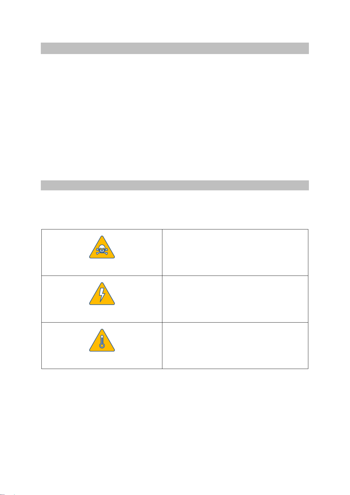
Danger
This symbol and signal word refer to a potentially
hazardous situation which could result in death or
injuries if ignored.
Caution electrical voltage
This symbol and signal word indicate live parts
with an immediate danger of death from electric
shock.
Caution hot
This symbol with a signal word indicates a
potentially hazardous situation that can result in
severe burns and scalds all over the body.

6
Caution
This symbol and signal word refer to a potentially
hazardous situation which could result in
personal injury, property and environmental
damage if ignored.
Caution
This symbol and signal word refer to a potentially
hazardous situation which could result in damage
to the equipment if ignored.
Info
This symbol indicates useful information and
recommendations as well as measures that will
prolong the value of your measuring and control
system.
1.2 Intended use of the device
Use these installation and operating instructions, the identification on the rating
plate and the technical data sheet to check whether the device is suitable for the
intended use/application. The device complies with the requirements of the
European Pressure Equipment Directive 2014/68/EU.
The device may only be used to indicate fill levels on containers.
The maximum values of the pressure and temperature range of the device must be checked
before installation. If the maximum allowable operating values of the device are lower than
those of the system on which it is to be installed, protective instruments for the device, such
as pressure reducers or similar, must be provided to avoid limit situations. The device may
only be used in accordance with the information in these installation and operating instructions
or for the parameters and applications agreed in the supply contract (see rating plate). The
operator of the direct water level indicator is obliged to familiarise himself on the compatibility
of the medium and the device. In case of doubt, contact the relevant installation manager or
site manager.
The correct installation position, alignment and flow direction of the device must be observed!
Before installing the IGEMA product on boilers or containers, it is essential to remove all
protective covers and, if necessary, the protective film from rating plates and sight glasses.
Caution
7
1.3 Safety at work
Before installation or carrying out maintenance work on the device, safe access
must be ensured and a secure working area with sufficient lighting must be
defined and marked out. Always use lifting equipment for heavy loads!
Before starting any work, carefully check which liquids or gases are or have been in the
pipeline. (flammable substances, irritating substances, substances hazardous to health) When
opening or dismantling the device, residues of the medium can escape. Subsequent fumes
are also possible in unpressurized and cold systems. Use designated PPE such as safety
goggles and respiratory protection!
Special attention must be paid to the condition of the environment around the installation or
maintenance site. Be aware of e.g.: potentially explosive atmospheres, lack of oxygen in tanks
and pits, dangerous gases/liquids,extreme temperatures, hot surfaces, firehazard (e.g. during
welding) and moving machine and system components. Protect yourself from excessive noise
by taking the required protective measures.
For all maintenance work or new installations, on new or existing boilers or vessels, it is
imperative to check thatthe boiler or vessel has been depressurised and that the pressure has
been safely reduced to atmospheric pressure. In principle, no system should be regarded as
unpressurized even if indicated by pressure measuring devices such as pressure gauges or
sensors. When releasing the pressure, make sure that no persons are in the release area.
Carefully check whether you and/or other persons in the vicinity need PPE to protect yourself
from external influences such as high and low temperatures, radiation, noise, danger to eyes,
loose objects that can fall down or chemicals.
There is always a risk of injury when handling large and/or heavy equipment. Observe the load
handling regulation as a minimum requirement for working with loads. Avoid handling the
device with your own physical force, e.g. by lifting, pulling, carrying, pushing or supporting it,
especially to prevent back injuries. Use lifting equipment to move heavy and bulky equipment
in accordance with Article 1, Section 2 of the German Load Handling Regulation
(LasthandhabV).
Under normal operating conditions the surface of the device can become very
hot! Under the maximum operating conditions, the surface temperature can
exceed 350°C. After shutting off or, if necessary, shutting down the boiler, wait
until the temperature has normalized to room level. To avoid the risk of burns
and scalds, always use PPE including safety goggles!
Danger
Caution
hot!

8
1.4 Safety instructions for this device
These installation and operating instructions are an integral part of the device
and must be forwarded to the responsible departments "Goods inward,
Transport, Installation, Commissioning and Maintenance". They must be kept in
such a way that the technical staff have access to these documents at all times.
If the device is passed on to a third party, these installation and operating
instructions must also be included in the national language of the third party.
Avoid shocks and hard contact during transport, as this can lead to damage. During
intermediate storage, the device must be kept dry and secured against damage.
When servicing the unit, make sure to use sharp-edged internal parts and avoid shards of
broken glass. There is a risk of cutting hands and arms! Always wear work gloves when
changing packing, valve seat and valve plug.
When returning goods to IGEMA GmbH, the applicable safety and environmental laws
according to GGVSEB [German ordinance on the national and international carriage of
dangerous goods by road, rail, and inland waterways] must always be observed. If there are
any risks to health or the environment due to residues or the device has a mechanical defect
this must be indicated when returning the device and the necessary precautionary measures
must be taken. If the returned goods are devices that have come into contact with or contain
hazardous substances, a safety data sheet must be enclosed, and the goods must be clearly
marked. In addition, the hazardous substance must be reported to the logistics service
provider.
1.5 Exclusion of liability
IGEMA GmbH Measuring and control technology will assume no liability if the above
regulations, instructions and safety precautions are not observed and followed. If they are not
expressly listed in the installation and operating instructions, changes to an IGEMA device are
carried out at the risk of the user.
2. Contents of the packaging
1. Sample cooler
2. Installation and maintenance instruction
Caution
9
3. General
•
These instructions must be carefully read before any work involving products supplied by
IGEMA is undertaken.
•
The installation procedure is a critical stage in a life of any device and care should be taken
to avoid damage to the sample cooler or equipment.
•
IGEMA sample coolers are designed to cool samples of boiler water or steam for analysis.
They prevent steam flashing-off from hot pressurized liquid samples, which can be
dangerous and will result in an incorrect water sample.
3.1 Note
•
Current regional safety regulations should be taken in to account and followed, while doing
the installation and maintenance work.
•
Handling, installation and maintenance work must be carried out by trained personnel. A
supervisor must follow and check all activities.
•
For the problems that cannot be solve with the help of this instructions, please contact the
supplier or the manufacturer.
•
The manufacturer reserves the right to change the design and material of this product
without notice.
3.2 General Safety Instructions
➢If malfunctionof any other equipment or system operationfailure may result in adangerous
overpressure, over temperature or even vacuum condition, a safety device must be
included in the system to prevent such situations.
➢Do not touch the equipment without appropriate protection during working operation
because it may conduct heat if the used fluid is at high temperature.
➢Before starting maintenance be sure that the equipment is not pressurized or hot. Even if
upstream and downstream isolating valves have been closed care should be taken since
fluid under pressure may be trapped between them.
➢The equipment must be used within the working temperature and pressure limits laid
down for them, otherwise they may fail (refer to nameplate and/or IS- Information Sheet).
Danger
10
➢Manual handling of products may present a risk of injury. You are advised to assess the
risks taking into account the task, the individual, the load and the working environment.
➢Before starting work ensure that you have suitable tools and/or consumables available.
Use only genuine IGEMA replacement parts.
➢Do not remove the nameplate attached to the equipment. Serial number and other useful
information are stamped on it.
➢This unit must not be used for oxygen applications, it has been specially designed for the
use specified here.
➢During the assembly work, apply protective measures against dirt.
➢Correct installation of the equipment is full responsibility of the contractor.
➢Sample coolers are designed to be applied in places protected from exposure to weather.
➢We recommend special constructions or protective measures for applications on the
outside or in adverse environments like corrosion-promoting conditions (sea water,
chemical vapours, etc).
4. Transport and Storage
4.1 Safety instruction
➢Handling and lifting of materials should be made with adequate equipment.
➢The sample coolers and equipment should be protected from impacts and forces during
transportation and storage.
➢The manufacturer doesn’t assume the responsibility of damaged equipment due to
inappropriate handling during the transportation and storage.
Danger

11
5. Installation
5.1 Safety Instructions
➢Account for over pressure conditions, according with the local laws or standards.
➢For the problems that cannot be solve with the help of this instructions, please contact the
supplier or the manufacturer.
5.2 Installation area requirements
•
The installation area should have easy access and provide enough space for maintenance
and removing operations.
•
The pipework before and after the sample cooler, must be sized in order to avoid that the
max flow speed recommended, for the fluid in question, is exceeded.
•
In order to allowinstallation and maintenance work without emptying the system, stop valve
should be installed upstream of the sample cooler water and steam supply.
5.3 Procedure
•
Prior to install check that the product is suitable for the intended application: materials and
pressure/temperature ratings.
•
Before installing remove plastic covers placed on flanges or connection ends. The
equipment has arrows or inlet/outlet designations. Be sure that it will be installed on the
appropriate direction.
•
Take care with jointing material to ensure that none may be permitted to block or enter the
sample cooler.
•
Sample coolers are recommended to be fitted with the centre line of the cooler in a vertical
position to ensure that the best results are obtained.
•
Stop valves are necessary on the cooling water and sample inlet.
•
The outlet cooling watershould be piped into a drain and be free of obstructions or isolation
valves.
•
The sample cooler pipe work should be properly supported and free from strain and it
should not be subjected to undue surges of pressure. The start-up condition should be
considered.
Danger

12
5.4 Dimensions
Pos.
Description
Sample cooler
1
Sample intake
2
Cooling water intake
2a
Colling water valve
3
Draining connection
4
Funnel to take a measuring jug
5
Sample outlet
5a
Thermometer unit

13
6. Start up
6.1 Safety instruction
Safety notice!
The device may become very hot as a result of the flow of the sample medium through
it and it must be regularly checked for a good seal. There is a risk of being burnt or
scalded. So appropriate protective clothing should be worn and relevant accident
prevention regulations should be observed.
➢
Current regional safety regulations should be taken into account and followed.
➢
Protective insulation and warning notice may be required.
➢
Until the start-up of an existing or a new plant, the following must be checked:
➢
All works are completed.
➢
The sample cooler is correctly installed.
➢
All the necessary safety devices have been installed.
➢
At start up, the presence of small particles in the fluid (dirt, scale, weld splatters, joint
particles, remains of Teflon tape, etc) may cause an imperfect operation of the cooler. If
this occurs, proceed to an accurate cleaning.
➢
Protection varnishes from pipes and flanges, fats, leftover paint, graphite, etc, should also
be carefully clean, because they can be dissolved in the fluids (like steam) and contaminate
the system.
➢
During operation high flow noises can be heard.
➢
To avoid the risk of scalding, before open or close the sample inlet valve, make sure that
the cooling water it is in the maximum flow.
Danger

14
6.2 Procedure to take boiler samples
1.
The cooling water stop valve (3) and the sample needle valve (2) should be closed.
2.
Open the cooling water valve slowly in order to avoid water hammer damaging, until the
input pressure reaches its limit.
3.
Open the needle valve slowly so that flashing does not occur. Allow to run approximately
10 seconds until fresh sample is drawn.
4.
Adjust the sample outlet temperature (if necessary), by regulating the sample needle valve
and the water valve.
5.
Make sure that there is an adequate equipment to collect the sample in place.
6.
After the sample collection, close first the sample valve and then the water valve but only
after a small period of time in order to condense or cool the remaining steam inside the
sample cooler.
6.3 Periodical checking
•
24 hours after the start up, it is recommended to check the pipe connections for leaks and
retighten the connections if necessary.
7. Maintenance
•
The sample cooler don’t need any specific type of maintenance. Regular inspection may
be recommended by local authorities according to specific or general pipe and/or vessels
assembly procedures.
•
For further information refer to relevant SC brochure or consult our sales office.
•
When reassembling make sure that all gasket faces are clean and always use a new
gasket.
7.1 Limiting Conditions
Minimum operating temperature: -10ºC
Design code: Igema - Merkblatt
LIMITING CONDITIONS
BODY
COIL
Model
Pressure
ba
r
Related
Temp. °C
Pressure
bar
Related
Temp. °C
SC32-
SC132
20
120
110
400
90
450

15
8. Products-returning
8.1 Safety Instructions
➢
Information regarding any hazards and precautions to be considered because of
contaminating fluids and residues or mechanical damage that may represent a health,
safety or environmental risk, must be provided in writing by the distributors and costumers
when returning products to IGEMA engineering.
➢
Health and safety data sheets regarding substances identified as hazardous or potentially
hazardous must be provided with the information mentioned above.
9. Loss of warranty
➢
LOSS OF WARRANTY: Total or partial disregard of above instructions involves loss of any
right to warranty.
This high-quality IGEMA product was designed, manufactured and tested with the
application of the QM System guidelines in accordance with DIN EN ISO 9001:2000.
If the device supplied indicates transport damage or gives cause for complaint in
spite of our final quality control, please contact our SERVICE department on
telephone +49 2501 92424-0 by return.

Table of contents
Popular Accessories manuals by other brands

Climate+
Climate+ CM-30000AP manual

KIT
KIT PWRP6BKNK user manual

Lightolier
Lightolier Lytecaster 2095 specification

Zephyr
Zephyr Adjustable Depth Liners AK088xAS installation manual

Balluff
Balluff BSI R11A0-XXR-CXP360-S75G user guide

PCB Piezotronics
PCB Piezotronics M221B03 Installation and operating manual

Rice Lake
Rice Lake RL50210 TA installation manual

Niceboy
Niceboy ION ORBIS Motion sensor user manual

krispol
krispol STARCUS ONE manual

LEGRAND
LEGRAND Wattstopper LMDW-102 quick start guide

PCB Piezotronics
PCB Piezotronics M102A14 Installation and operating manual

Jetboards
Jetboards KYMERA BODY BOARD User and safety manual


