Igema EWLI-3B Owner's manual

ElectronicRemoteWaterLevel
IndicatorTypeEWLI-3B
forusewithlevelprobes:EL65orEL60
D-05-B-30869-EN-0
Issuedate11/2015

2
TableofContents
1.RisksandSafetyPrecautions..........................................................................................................................................................................3
1.1Generalsafetyinstructions...................................................................................................................................................................3
1.2Exclusionofliability................................................................................................................................................................................4
2.Contentsofthepackaging.............................................................................................................................................................................5
3Useincompliancewithregulations..............................................................................................................................................................5
4.SystemDescription..........................................................................................................................................................................................5
4.1Components............................................................................................................................................................................................5
4.2Function....................................................................................................................................................................................................6
4.3Setup.........................................................................................................................................................................................................7
4.4Componentsofthecontrolunit(CU)..................................................................................................................................................8
4.5Operation..................................................................................................................................................................................................8
4.6Errormessages........................................................................................................................................................................................9
4.7Overviewofthesystemproperties.....................................................................................................................................................9
4.8Displayunit(DU)...................................................................................................................................................................................10
5.AssemblyandInstallation............................................................................................................................................................................11
5.1Add-onhousing.....................................................................................................................................................................................11
5.1.1Installationdimensionsanddescriptions..............................................................................................................................12
5.1.2Installation...................................................................................................................................................................................13
5.2.ControlunitCU.....................................................................................................................................................................................13
5.2.1Installationdimensionsanddescriptions..............................................................................................................................13
5.2.2Powerconnection......................................................................................................................................................................14
5.3.MeasuringunitMU..............................................................................................................................................................................16
5.4DisplayunitDU(optional)...................................................................................................................................................................17
5.4.1Installationdimensionsanddescriptions..............................................................................................................................17
5.4.2Powerconnection......................................................................................................................................................................18
5.5Systemconnection...............................................................................................................................................................................18
6.ConfigurationviaMenu................................................................................................................................................................................19
7.Specialfeaturesofsystemsetup.................................................................................................................................................................22
8.Commisioning.................................................................................................................................................................................................22
8.1Systemsetup..........................................................................................................................................................................................22
8.2Factorysettings.....................................................................................................................................................................................22
8.3Commisioningwhenstartinguptheboiler.....................................................................................................................................23
8.4Commisioningduringboileroperation............................................................................................................................................23
9.TechnicalData.................................................................................................................................................................................................23
9.1Devicedata.............................................................................................................................................................................................23
9.2Mainstransformer................................................................................................................................................................................25
9.3Maximumratingsofpotentialfreecontacts...................................................................................................................................25
9.4Dataplate...............................................................................................................................................................................................26
10.SystemMaintenance...................................................................................................................................................................................26
10.1Depressurisingadd-onhousing.......................................................................................................................................................26
10.2Dismantlingandfittingprobes........................................................................................................................................................27
11.Faultanalysisandrectification..................................................................................................................................................................27
12.Warranty........................................................................................................................................................................................................29
13.DeclarationofConformity..........................................................................................................................................................................30
14Attachment....................................................................................................................................................................................................32

3
Safetyinstructions
1.RisksandSafetyPrecautions
1.1Generalsafetyinstructions
1.Avoidanceofriskstopersonsandproperty
Onlyusethedevicesuppliedinaccordancewiththeintendedplanning.
Extensionsandmodificationstothedevicemustonlybecarriedoutwithourapproval.
Observeaccidentpreventionregulationsandsystem-specificsafetyinstructions.
Readandobservefittingandoperatinginstructions.
Thedevicemustonlybefittedandputintooperationbyappropriatetrainedpersons.
2.Limitationsofuse
Thedevicemustonlybeusedinaccordancewiththedetailsintheseoperatinginstructionsorfor
theparametersagreedinthesupplycontract(seenameplate)andtheapplication.
Approvalforthisdevicelosesitsvalidityifchangesnotauthorisedbyushavebeenmade.
Thesafetyofthewholeboilersystemintowhichthisdeviceisfittedliesintheresponsibilityofthe
installerofthesystem.
Ifthisdeviceisinsertedincorrectlythefunction/protectionexpected from this device may be
impaired.
3Avoidanceofrisksanddamage
DisseminatetheInstallationandoperatinginstructionstothedepartmentsresponsiblefor“goods
in,transport,assembly,commissioningandmaintenance”.
If this device is passed on to third parties, these Installation and operating instructions in the
relevantlanguageofthecountrymustaccompanyit.
Assemblyworkonthedeviceshouldonlybecarriedoutbytrainedstaffspeciallycommissioned
andonlyifthedeviceisdisconnected.
ReadandobservetheInstallationandoperatinginstructionscarefully and keep them in a safe
place.
Takenoteofandfollowthesafetyinstructionsprintedinbold and highlighted in the
individualsections!
Whentransporting,avoide.g.knocksandputtingdownheavily,thiscanleadtodamage.
Forintermediatestorageensurethatthestoragelocationissuitableforthedevice.
Thestoragelocationmustbedryandthedevicesecuredagainstdamage.
Thisdevicemustnotbeusedinareasatriskofexplosion.

4
4.Symbols
IntheseInstallationandoperatinginstructions,safetyinstructionsarespeciallymarkedwiththe
followingsymbols:
meansthatiftheyarenotobservedthereisrisktolifeand/orsignificantdamageto
propertymayoccur.
Danger
meansthatattentionisparticularlydrawntotechnicalrequirements.
Attention
1.2Exclusionofliability
IGEMAGmbHMess-undRegelsystemewillassumenoliabilityiftheabove-mentionedregulations,
instructionsandsafetyprecautionsarenotnotedandfollowed.

5
2.Contentsofthepackaging
1EWLI-3Bconsistingof:
Add-onhousingwithnumberofprobesordered(EL65(<=32bar)orEL60(>32bar))
Measuringunit(MU);fittedontotheadd-onhousingandfullywired
Controlunit(CU)
1Powersupply(top-hatrail)forsupplyingthecontrolunit(CU)with24VDC
1setofinstallationandoperatinginstructions
3Useincompliancewithregulations
The EWLI-3B (electronic water level indicator) is used as a remote water level indicator for steam
boilersor(pressure)tankswithelectricallyconductiveliquids.Dependingontheregulationsapplied
theEWLI-3Bcanalsobeusedasamulti-controlsystem(indicator-limiter‒controller),bymeansof
theprogrammableassignmentofoutputs(change-overcontacts)relativetothelevels.TheEWLI-3B
add-onhousingisfastenedtotheprocessconnectionsprovidedonthetank.
The EWLI-3B has been developed in accordance with the requirements of EC Directive 97/23/EC
(2003)andthestandards:
DINEN129521-7, DINEN129531-6,
DINEN610006-2 DINEN610006-4
DINEN610003-2 DINEN610003-3
DINEN610101
Thedeviceisusedformeasuringthelevelofaliquid.Itisusedpredominantlyonsteamboilers.With
the aid of probes the EWLI-3B measures the current level in theadd-onhousingandthusinthe
boiler.Withtheabilityofhavingupto32Probes(minimum2)oneachievesaquasi-continuouslevel
display,takingintoaccountaminimumprobespacingof36mm.
4.SystemDescription
4.1Components
-Add-onhousingwithnumberofprobesordered(EL65(<=32bar)orEL60(>32bar))
-Measuringunit(MU);fittedontotheadd-onhousingandfullywired
-Controlunit(CU)withseparatepowersupplyunit;fortop-hatrailfittinginthedistributioncabinet
-Displayunit(DU)‒optional
-variousCAN-Busconnectingcables

6
4.2Function
TheEWLI-3Blevelindicatorworksonthebasisoftheconductivefilllevelmethodofmeasurement
whereby the electric conductivityofthemediumisused.Theconductivity of the medium is
measuredinµS/cm.Forthesecurefunctioningofthismethodof measurement a minimum
conductivityofthesubstancetobemeasuredisrequired.
Theconductivemethodofmeasurementmakestwostatements:electrodesubmergedorelectrode
emerged.
Themeasuringunit(MU)feedsandevaluatestheinstalledprobes(2to32innumber).Thestateof
theprobesattachedintheadd-onhousingisthensenttothecontrolunit(CU).
Thecontrolunit(CU)determinesthereactionsnecessaryfromthereceiveddatafromthemeasuring
unit(MU).
SystemstatusLCDdisplayLEDs1*4mA..20mAOutputcontact2*
Correct
operation
IGEMA
EWLI3-CU
4mA+
(16mA/numberofprobesfitted)
x
Numberofprobessubmerged3*
A:activated
F:activated
Z:dependingonassignment/
programming
correctoperation
withfailureofone
24Vsupply4*
(40)PIN1
powertoolow5*
4mA+
(16mA/numberofprobesfitted)
x
Numberofprobessubmerged3*
A:activated
F:activated
Z:dependingonassignment/
programming
Systemerror(65)MU
CANBUSnodata5*
2mA A:nopower/stateofrest
F:nopower/stateofrest
Z:allwithoutpower
Waterlevel
alarm
(LLW/HHW)
(33)
LLWalarm5*
4mA+x(LLW)
20mA‒y(HHW)
x,ycorrespondingto
programmedProbe
A:nopower/stateofrest
F:activated
Z:dependingonassignment/
programming
Wateroversteam (“No”)please
checkprobe:“No”5*
2mAA:activated
F:nopower/stateofrest
Z:dependingonassignment/
programming
Probeerror7*
(LLW/HHW)
(33)
LLWalarm5*
2mAA:nopower/stateofrest
F:nopower/stateofrest
Z:dependingonassignment/
programming

7
Probeerror6*
(assigned)
(“No”)please
checkprobe:“No”5*
2mAA:nopower/stateofrest
F:nopower/stateofrest
Z:assignedwithoutpower;
Rest:dependingon
assignment/progr.
Probeerror6*
(notassigned)
(“No”)please
checkprobe:“No”5*
2mAA:activated
F:nopower/stateofrest
Z:dependingonassignment/
programming
1*FullylitLED:continuouslight/halflitLED:flashing
2*Description: “A”Alarmoutput “F”Erroroutput “Z”Assignedoutput
3*Example: 12probes/4submerged: ...mA=9.3mA(4mA+(16mA/12)*4)
16probes/7submerged: ...mA=11.0mA(4mA+(16mA/16)*7)
15probes/13submerged: ...mA=17.9mA(4mA+(16mA/15)*13)
4*Whenusing2powersupplyunits
5*Example
6*SeeChap.7Specialfeaturesofsystemsetup
7*AsLLW/HHW-Alarmhaspriority,thismessageisshown.However,consideringtheLED-display(yellowflashesalso)the
probefaultisrecognisable.
Safe operating mode during which the output contacts of the device go into rest position,
correspondsatthesametimetothede-energisedstateofthecontrolunit.
TheDU(optional)displayunitcanbeusedasaremoteindicator.ThestatusLEDsshowthesameas
theLEDsoftheCU.InadditioneachprobeislinkedtoanLED.Greenshowsasubmergedprobe,reda
probeinthesteamspaceandaflashingLEDmeansaprobeinanincorrectstate.Theoutputcurrent
ofthe4mA..20mAoutputoftheDUiscalculatedlikethatoftheCU.
4.3Setup
ForensuringhighavailabilityIGEMArecommendstheuseof2powersupplyunits(redundancy).In
termsofhardwaretheCUisdesignedforoperationwith2powersupplyunits.
Boththemeasuringunit(MU)andthecontrolunit(CU)have2independentelectroniccircuitswith
their own processors. All processorscarryoutregularself-tests for internal faults in the electronic
circuit.Thisprovidesself-monitoringofthedeviceandthusahighersafetystandard.
Measuringunit:
Bothelectroniccircuitsrecordthestateoftheprobesandsendittothecontrolunit.
Controlunit:
Bothelectroniccircuitsevaluatethestatusmessagesofbothelectroniccircuitsofthemeasuring
unit.Ifbothstatusmessagesareidenticaltherequiredreaction(Chap.4.2)iscarriedout.
Aplausibilitychecktakesplace.
8
Eachelectroniccircuitswitchesits“own”relay(SPDT)forthecorrespondingoutput.Onlywhen
bothrelaysofbothelectroniccircuitsaredriven(activated)equally(e.g.duringnormaloperating
status)istheoutputactive.
Theoutputcontactsdonothaveanylatching.Theswitchingbehaviouris
exclusively in line with the desired specified (programmed) state. If latching is
required,thismanuallocking(latching)mustbecarriedoutonsite.
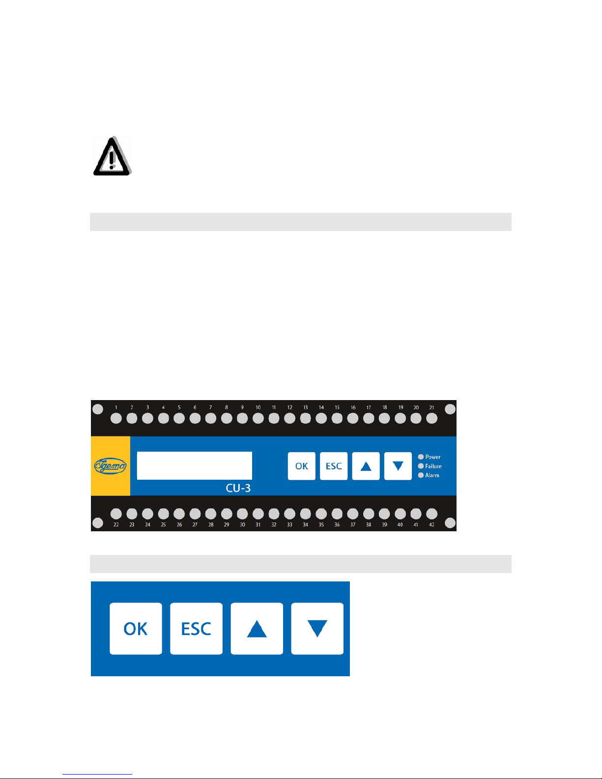
4.4Componentsofthecontrolunit(CU)
Thecontrolunitcontains:
1LCDdisplay(2-lineeach16characters)forcommunicationwiththeoperator
(programmingandinformationdisplay)
4buttonsforprogramming
3LEDsasstatusindication
1SPDTalarmoutputforfilllevelsignalling(fixed);thecorrespondingprobes(LWand/orHW)
canbefreelychosen
1SPDTerroroutput(fixed);outputisinstateofrest,ifanysystemerroroccurs
7SPDToutputsfreelycontrollable(seeassignmentplanChap.:5.2.2)
14mA..20mAoutputforloadsupto500Ω,notgalv.isolated
4.5Operation
OperationoftheEWLI-3Biscarriedoutbythe4buttonsoftheCU.ThisisdescribedinChap.6
“ConfigurationviaMenu”.
IGEMA
EWLI3-CU

9
4.6Errormessages
IntheLCDdisplayerrorsfromtheevaluatorandprobesaredisplayednumber-codedandinplaintext
abbreviations.
IfthereisaDUpresent(optional),errorsbyevaluatorandprobesare displayedinthe7-segment
displaynumber-codedand2-digit.
ForanalysisanderrorcorrectionseeChap.10.
4.7Overviewofthesystemproperties
-Upto32probes(minimum2probes)forquasi-continuouslevelmeasuring
-CanbeuseduptoPS=200bar//TS=367°C
-Doublepowersupplyforhighavailability(redundancy)withdisplayoffailureofonepowersupply
-Self-monitoringelectronicsforhighsystemsafetyduringmonitoringfunctions
-wirebreakagemonitoring
-Adjustableswitchingdelayonalloutputsforavoidingfalsesignals
-1alarmoutput(SPDT)forthereactionincaseoflowwaterand/oroverfilling
-1erroroutput(SPDT)forthedisplayof(electronic)systemerrors
-7userspecificandprogrammableoutputs(SPDT)enable:
*individualswitchpointse.g.hornwhenexceedingorfallingbelowafilllevel
*doubleswitchpointse.g.forapumpcontrol
Inthecaseofidenticalprogrammingoftwooutputsa“DPDToutput”ispossible.
-14mA..20mAoutputforloadsupto500Ω,notgalv.isolated
-Remoteindicator(DU,optional)with4mA..20mAoutputforloadsupto500Ω,notgalv.isolated,
asmanyasdesired

10
4.8Displayunit(DU)
Therearetwoversionsofthe(optional)displayunitDU:
-systemswithupto16probeshaveasingle-rowLED-display
-systemswith17upto32probeshaveadouble-rowLED-display
ForeachprobeaLEDindicatesthestateoftheprobe:
-green:probesubmergedinwater
-red:probeinsteam
-surplusLEDs(e.g.13,14,15,and16ifthesystemhas12probes)arenotactivatedandremain
dark
Theconditionofthesystemisindicatedvia3status-LEDs(identicaltotheLEDsoftheCU/seeChap.
4.2).
Ifadiscrepancyinthemeasurmentisdetected(waterabovesteam),theprobethatindicateswater
flashesgreen(seeChap.4.2).
IfaprobefailureisdetectedthecorrespondingLEDflashesred(seeChap.4.2).

11
5.AssemblyandInstallation
5.1Add-onhousing
Measuringunit
MU
Processconnection
Probes
Casing

12
5.1.1Installationdimensionsanddescriptions
A: Boilerconnectiondimensions
E: Displayarea
D: Minimumwaterlevel
T: Distancebetweenprobes
L: Lateraldismantlingdimensions

13
5.1.2Installation
Theadd-onhousingissuppliedfullywired.
Itisattachedviatheprocessconnectionsinaccordancewiththerules/regulationsontheboiler.
Becauseofthetemperature-dependentdensityofthemedium,itmustbeensured
thataflowthroughtheadd-onhousingwiththemediumisensured,e.g.througha
forcedcirculation(inclination).
5.2.ControlunitCU
The control unit and also the associated power unit are supplied in a plastic plug-in housing for
fittingintoswitchcabinets.ThehousingisdesignedforquickfittingwithaspringcatchfortheDIN
EN50022standard35mmcarrierrail.
Ensureprotectionclassinaccordancewithcurrentregulations
WithsnapfasteningforstandardDINEN5002235mmcarrierrail
Fixdeviceonstandardcarrierrailbymeansofthesnapfastening(4).
5.2.1Installationdimensionsanddescriptions
Frontview:
Sideview:
IGEMA
EWLI3- CU

14
5.2.2Powerconnection
Thedeviceterminalstripisliveduringoperation!!
Beforeworkingonthedevicedisconnectitfromthemains!!
If inductive equipment is connected, voltage peaks occur when switching off.
For this reason connected inductiveequipment(e.g.contactor)must be
providedadditionallywithanRCcircuit:e.g.0.1µF/100Ω.
The output contacts are only switched when both electronic circuits energise the
correspondingrelays(Chap.4.3)
Assignmentplan:
Upperbar/contacts1‒21(fortheoutputcontactstherestpositionisdisplayed):
Whenusingonlyone24Vsupply,contacts1and2mustbebridged.
AlarmOut
FailureOut
15
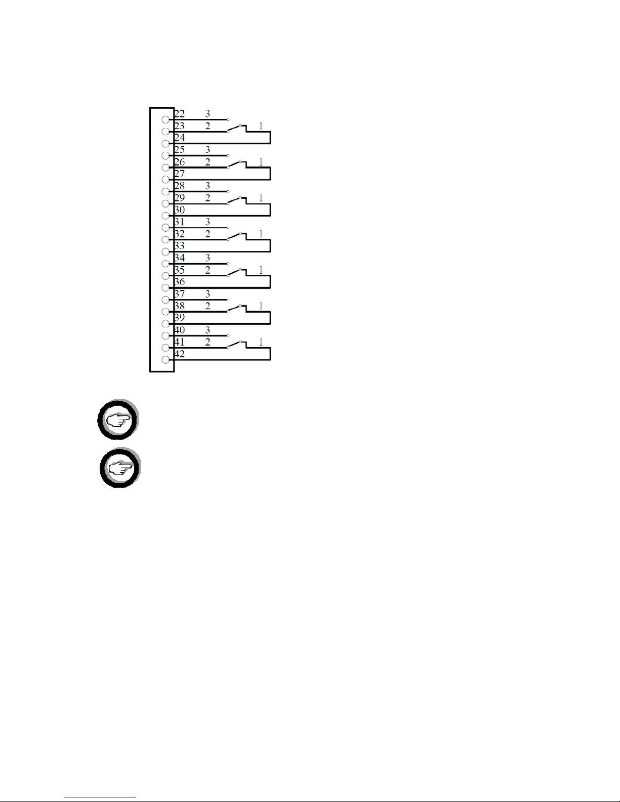
Lowerbar/contacts22‒42:(freelyprogrammableoutputchangecontacts)
(restpositiondisplayed)
TheCAN-Buscontrol cable has to be a 4-wire, twinstranded, shieldedcable(e.g..
UNITRONIC®FDPDeviceNetTMTHICK(PUR)//option:IGEMAArt.no.35-10058).
Forthecurrentloopinterface(4mA..20mA)ashieldeddatacable(2x0,34mm2or
2x0,75mm2)(e.g.UNITRONIC®PURCP)hastobeused.
Out1
Out2
Out3
Out4
Out5
Out6
Out7
16
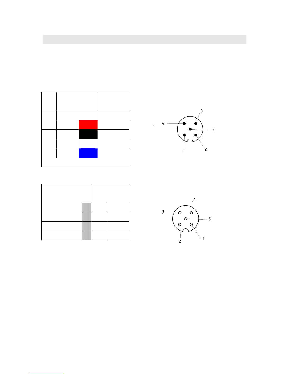
5.3.MeasuringunitMU
Themeasuringunitisfixedtotheadd-onhousingandtheprobesarefullywired.Theconnectionto
thecontrolunittakesplaceviaa5-pinplugatthebottomoftheswitchingcabinetofthemeasuring
unit.
Ifnoassembledcableisordered,theassemblingoftheenclosedplugsocketisdoneaccordingtothe
DeviceNetTMBUSsystem.
assignmentofterminalsontheMUcircuitboard:
connectingterminal signal
DeviceNetTM
2 o CANL
3 o CANH
4 o V-
5 o V+
PIN Leadcolor signal
DeviceNetTM
1 Drain
2 RD V+
3 BK V-
4 WH CANH
5 BU CANL
Screenfixedtohousing
plugsocketM12,5-pin,A-coded
plugM12,5-pin,A-coded
17
5.4DisplayunitDU(optional)
The(optional)displayunitisdesignedasswitchboardmountabledevice.
Forfastening,ascrewsystem(switchboard)oratop-hatrailadapterisavailable(seeAccessories).
TheDUissuppliedasstandardwith120Ωbusterminatingresistor(contact3‒contact4//CANL-
CANH)
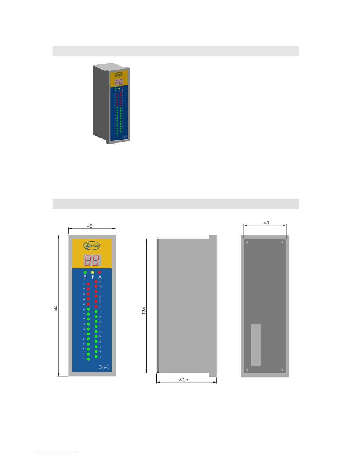
5.4.1Installationdimensionsanddescriptions

18
5.4.2Powerconnection
Aplug-inconnectorisledoutattherear.Theassignmentis:
*TheDUissuppliedasstandardwith120Ωbusterminatingresistor(terminator).
If the DU is not the last device (see Chap 5.5), it must be removed when fitting (the CAN-Bus).
IftheDUisthelastdevice,theCAN-Busmustsimplybeadded.
5.5Systemconnection
Anoverviewoftheelectricalconfigurationoftheoverallsystemisgivenbythefollowinggraphics:
(Theillustrationshowstheredundantconfigurationwith2powersuppliesand3optionalDUs.)
ThebusterminatingresistorisalreadyimplementedintheMU.Thusonesideofthebus(ontheleft
inthediagram)issealedoff.TheothersideofthebusmustbeterminatedonCANHandCANLon
thelastdeviceviaa120Ohmresistance.
OnlyIGEMAcomponentsbelongingtotheEWLI-3BsystemmaybeoperatedonthisCAN-Bus
controlcable(1xMU;1xCU,XxDU).Theshort-circuit-proof24VvoltageoftheCAN-Busis
120Ω*
Terminator
Terminator
Mainsadapter
Mainsadapter

19
designedexclusivelyforthesupplytothesystemandmustnotbeusedfortheexternalsupply
offurtherdevices.
Themaximumlengthofthebuslinecanbeatotalof500m.
Whenfitting,bearinmindthatthecablemustnotcomeintocontact with heat-
conductingparts.
The CU control unit can supply the measuring unit (MU) and up to 3 display units (DU). The
connectionoffurtherDUsispossible.Howeverthesemustthenbeprovidedwiththeirownseparate
andindependent24Vsupply(observeChap.9.2!).
6.ConfigurationviaMenu
ThemenuoftheEWLI-3Bisdividedintotwolevels:
Level1|Level2
Themenuisaccessedbypressingthe“OK”key.AmenuitemofLevel1willappearintheLCDdisplay.
Withthekeys“▲”or“▼”youcanchoosebetweenthemenuitemsoftherespectivelevel.Theupper
rowis“active”.
Bypressingthe“OK”keyyouwillgettothenextleveldownorconfirmtheentry.
Bypressingthe“ESC”keyyoucangettothenextleveluporoutofthemenuwithoutthecurrent
entrybeingsaved.(With“OK”confirmeddataarealreadysavedandremainso.)
ThemenulanguageisEnglish.
Automaticmenu exit after2minutesifno key operationiscarriedout(without saving /see
“ESC”).
Themenuconsistsof4items.Items1to3arepurelyforinformation!Whereasitem“1.1Probestate”
andaboveallitem“1.2Relaystate”areveryusefulforcheckingthecorrectprogrammingandthe
desiredswitchingoperations.
(Youfindexamplesforprogrammingintheattachment)

20
Diagram:
|---1.SystemInfo---
||-1.1.Probestate|
||-1.2.Relaystate|
||-1.3.MUsystemA|
||-1.4.MUsystemB|
|---2.Supply---
||-2.1.InputPin1|
||-2.2.InputPin2|
||-2.1.OutputPin3|
|---3.Version---
||-3.1.Control|
||-3.2.Measurement|
||-3.3.Display|
|---4.Settings---
||-4.1.Backlight|
||-4.2.Password|
|---|-----Afterenteringvalidpassword------------------
||-4.3.Relaysetup|
||-4.4.LLWAlarm|
||-4.5.HHWAlarm|
The password is: 123; It activates the menu items 4.3, 4.4 und 4.5 and its only
functionisthepreventionofunintentionalprogrammingofsystemfunctions.
Menudescription:
1.1Probestate: Thestateoftheprobesisdisplayed,“w”forwater,“s”forsteam;
For illogical states, for example water over steam, the submerged
probeisdisplayedincapitals(e.g.“W”).
1.2Probestate: Theswitchstateofthe9outputsisdisplayed“0”forrestposition(NO)
and“1”foractivated.
1.3/1.4MUSystemA/B: Temperatureoftherespectiveelectronicsofthemeasuringunit.
2.1InputPin1: Supplyvoltage1(theoretical24V)
2.2InputPin2: Supplyvoltage2(theoretical24V)
2.3OutputPin3: Can-Bus‒voltage(theoretical23.5V)
3.1Control: VersionnumberCU
3.1Measurement: VersionnumberMU
3.1Display: VersionnumberDU
Table of contents
Popular Touch Panel manuals by other brands


Extron electronics
Extron electronics TLP Pro 1230WTG user guide

weintek
weintek MT-600 Series Installation instruction

Winmate
Winmate GC Series quick start guide

PZRacing
PZRacing GearTronic2 GT400 user manual

Intel
Intel Platform Panel PC User manaul

Avery Weigh-Tronix
Avery Weigh-Tronix WI-130 Software user manual


