IGM MRBP.424321.001UM User manual

CO Ltd. I G M -D e te c to r
Address: 27 Engels Prospect,
building 5, litera A
Saint-Petersburg
194156, Russia,
Tel: 8 (800) 234-66-90
Website: www.igm-pribor.ru
E-mail: support@igm-pribor.ru
EMI-SSD-1M CONTROL UNIT
USER MANUAL
MRBP.424321.001UM
Saint-Petersburg
2020

C on t en t s
1 Description and operation ........................................................................................................... 4
1.1 Intended use .......................................................................................................................................4
1.2 Application scope................................................................................................................................4
1.3 Technical specifications ......................................................................................................................5
1.4 Construction and overall dimensions .................................................................................................6
1.5 Device and principle of operation.......................................................................................................9
1.6 Marking and sealing..........................................................................................................................10
1.7 Packaging ..........................................................................................................................................11
2 Safety precautions..................................................................................................................... 12
3 Correct use................................................................................................................................ 13
3.1 Operating hints .................................................................................................................................13
3.2 Operating limits.................................................................................................................................13
3.3 Preparation .......................................................................................................................................13
3.4 Getting started..................................................................................................................................15
4 Maintenance service ................................................................................................................. 17
4.1 General hints.....................................................................................................................................17
4.2 Maintenance routine ........................................................................................................................17
5 Storage and transportation........................................................................................................ 19
6 Utilization ................................................................................................................................. 19
Appendix A Pin assignment .......................................................................................................... 20
Appendix B Connection diagram................................................................................................... 22
Appendix C Modbus RTU Protocol description.............................................................................. 25

I n tr od uc t io n
3
MRBP.424321.001UM Version 1.0 27/01/2020
This user manual (UM) is intended to describe design, principle of operation and mainte-
nance service of control unit EMI SSD-1M (EMI SSD-1M). Mounting, tuning and maintenance service
of EMI SSD-1M must be carried out by suitably trained specialists after having studied this UM.
This UM is applicable to all current modifications of EMI SSD-1M.
Warning!
Study this UM before mounting and operating of EMI SSD-1M.
Operating not in accordance with the requirements of this UM may lead to the
failure of the control unit.
EMI SSD-1M identification when ordering:
EMI-SSD-1M-AB
EMI –manufacturer IGM –detector
SSD-1M –model
A –LoRa: 1 –present, 0 –not present
B –HART: 1 –present, 0 –not present
Example identification: EMI-SSD-1M-01 –manufacturer IGM-detector, model SSD-1M, with built-in
HART modem and without built-in LoRa Wi-Fi unit.

D es c ri p ti on a nd o p er a tio n
4
MRBP.424321.001UM Version 1.0 27/01/2020
1Description and operation
1.1 Intended use
1.1.1 EMI-SSD-1M is a multiple-line controller intended for:
-continuous analogue and digital signal reception from gas detectors;
-processing and storage of received data;
-data transferring to a higher lever system;
-external circuits switching;
-audio and light alarm in case of set threshold exceeding.
1.1.2 EMI SSD-M1 can be used as control unit within control system EMI-M1.
1.2 Application scope
1.2.1 Oil and gas fields, oil and gas processing plants, oil and gas storages, chemical indus-
tries etc.
Typical facilities demanding gas pollution control:
-raw materials loading/unloading areas;
-raw materials and manufactured goods storages;
-pump stations;
-compressor stations;
-working areas of plants etc.

D es c ri p ti on a nd o p er a tio n
5
MRBP.424321.001UM Version 1.0 27/01/2020
1.3 Technical specifications
1.3.1 EMI-SSD-1M technical specifications are shown in table 1.
Table 1
Specification
Value
Supply voltage
12-32 VDC
Power consumption
2,5 W (up to 120 W while supplying gas detectors from EMI-
SSD-1M)
Control
membrane keypad (8 buttons)
Data storage ability
plug-in SD card
Input signals:
Input signal type
-RS-485, Modbus (1-32 detectors);
-4-20 мА (1-8 detectors);
-Bell 202 Current, Hart-6 (1-8 detectors).
Inaccuracy
limit of permissible reduced error of current signal meas-
urement (4 - 20) mA:
-+15°С…+35°С = ± 0,2%;
--10°С…+15°С and +35°С…+50°С = ± 0,5%.
Output signals:
Digital output interface
RS-485 Modbus
Wireless communication standards
- Bluetooth 2.0
-LoRa
Relay (discreet) outputs
3 relays: Threshold 1, Threshold 2, Emergency.
16 Аat 250 WAC, 16 Аat 24 WDC
Indication
OLED display, 2 LEDs: alarm, work
Sound alarm
85 dB
1.3.2 Device elements isolation
Galvanically isolated elements scheme and galvanic insulation strength are shown on fig.1. In-
sulation strength value is stated for normal climatic conditions test, action time –1 minute.

D es c ri p ti on a nd o p er a tio n
6
MRBP.424321.001UM Version 1.0 27/01/2020
EMI-SSD-1M
Supply
1500 W
Microcontroller
Display
Relay
2500 W
RS-485
2500 W
Keypad
RS485
2500 W
channel 1
Current
loop 4-
20mA
2500 W
SD card
channel 2
channel 3
Bluetooth
channel 4
channel 5
LORA
channel 6
channel 7
channel 8
HART
Figure 1 EMI-SSD-1M elements isolation
Notice:
- EMI-SSD-1M galvanically isolated elements graphic symbol.
1.4 Construction and overall dimensions
1.4.1 Structurally, the device is made in a plastic case designed for fixing on a DIN rail. The
housing has a stepped shape.
EMI-SSD-1M overall dimensions are shown on fig. 2 and 3.
EMI-SSD-1M overview is shown on fig. 4 and 5.
EMI-SSD-1M weight –500 gr.

D es c ri p ti on a nd o p er a tio n
7
MRBP.424321.001UM Version 1.0 27/01/2020
Figure 2 –EMI-SSD-1M w/o LoRa antenna overall dimensions
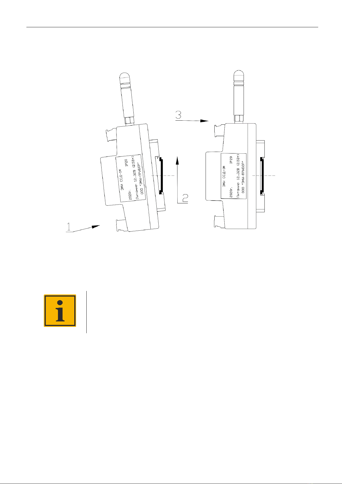
Figure 3 –EMI-SSD-1M with LoRa antenna overall dimensions
Notice:
Antenna is installed depending of LORA radio module presence.

D es c ri p ti on a nd o p er a tio n
8
MRBP.424321.001UM Version 1.0 27/01/2020
Figure 4 –EMI-SSD-1M front view
Figure 5 –EMI-SSD-1M back view

D es c ri p ti on a nd o p er a tio n
9
MRBP.424321.001UM Version 1.0 27/01/2020
1.5 Device and principle of operation
1.5.1 EMI-SSD-1M is able to connect 8 gas detectors simultaneously via «current loop» ana-
logue interface and «Bell 202» («HART» protocol) digital interface or 32 gas detectors via the RS-485
interface («Modbus RTU» protocol). In total up to 40 gas detectors can be connected to the device.
1.5.2 Data may be transferred to a higher level system via «RS-485» interface («Modbus
RTU» protocol), via wireless communication standards «LoRa» и «Bluetooth».
1.5.3 Data and events are archived on external SD card..
1.5.4 External circuits switching is carried out by 3 relays, shifting can be tuned.
1.5.5 EMI-SSD-1M channels tuning and configuration is carried out in control unit menu by
built-in key-pad and OLED-display, as well as by «Bluetooth».
1.5.6 Battery CR2032 for internal clock continuous operation is installed in EMI-SSD-1M.
1.5.7 Latches for fixing the device on a DIN rail are on the rear cover.
1.5.8 Indication alarm and control elements are on the upper front surface:
- OLED-display allows visually track changes in the values of variables from connected sen-
sors, and display a custom menu.
- two LED indicators:
a) «Operation»(green) –indicates that device is turned on;
b) «Failure»(red) –lights up in case of set threshold exceeding or connected detectors fail-
ure.
- piezoelectric radiator makes sound in case of set threshold exceeding or connect-
ed detectors failure.

D es c ri p ti on a nd o p er a tio n
10
MRBP.424321.001UM Version 1.0 27/01/2020
- 8 control and menu navigation buttons:
- turn on/turn off/reload;
- up;
- down;
- left;
- right;
- confirmation (main mode –cannel information request);
- cancel/back (main mode –menu request);
- emergency mute (handshaking).
On the lower front surface there are EMI-SSD-1M detachable joints (terminal blocks), the
purpose of which is described in Table A1 of Appendix A. Actuators, sensors, communication lines
and power supply are connected to these joints. Split design of the terminal blocks allows to perform
hot-swapping.
SD-card slot and antenna LоRa connector are located on the upper side surface of EMI-SSD-
1M in accordance with Figure A1 of Appendix A.
1.6 Marking and sealing
1.6.1 EMI-SSD-1M marking must contain:
- name EMI-SSD-1M;
- manufacturer trademark;
- electrical terminals and external connections identification;
- light indication;
- supply voltage and power consumption value;
- IP degree of protection;
- factory serial number;
- manufacture year.
1.6.2 Sealing

D es c ri p ti on a nd o p er a tio n
11
MRBP.424321.001UM Version 1.0 27/01/2020
EMI-SSD-1M is sealed by non-removable tags «WARRANTY». Seals «WARRANTY» locations-
rear cover, over the location of one of the screws.
1.7 Packaging
EMI-SSD-1M is packed in transport box of the manufacturer in compliance with GOST 23170-
78. The accompanying documents for the delivery set are also placed in the box.

S a f e ty pr e c au ti on s
12
MRBP.424321.001UM Version 1.0 27/01/2020
2Safety precautions
Warning!
It is prohibited to use EMI-SSD-1M in hazardous areas as well as in the atmos-
phere containing acids, alkalis, oils and other aggressive substances.
2.1 Any person who has studied this UM and has been briefed on safety precautions is ad-
mitted to operate EMI-SSD-1M.
2.2 While operation and maintenance general requirements GOST 12.3.019–80, «Safety
code for operation of electric installations of consumers», «Workplace safety rules during operation
of electric installations of consumers» and «Regulations for Electrical Installation» must be observed.
2.3 Any connections to EMI-SSD-1M and maintenance service must be carried out only when
the power supply of the device itself and of the devices connected to it is switched off.
2.4 Do not allow moisture ingress on the contacts of the output connectors and the internal
elements of EMI SSD-1M.
2.5 It is prohibited to use EMI-SSD-1M with any damages.
2.6 Repairing of EMI-SSD-1M must be carried out only by the manufacturer’s personnel or
persons authorized by the manufacturer for repairs.

C or r ec t u se
13
MRBP.424321.001UM Version 1.0 27/01/2020
3Correct use
3.1 Operation hints
3.1.1 EMI-SSD-1M operation must be carried out according to this UM.
3.1.2 Connection and disconnection of EMI-SSD-1M to analogue outputs as well as to digital
interface must be performed only after disconnecting power circuits.
Warning!
Manufacturer is not responsible for EMI-SSD-1M fault or for damage, resulting
from improper or not specified in this UM use of the device.
3.2 Operation limits
3.2.1 EMI-SSD-1M is not intended for operation in hazardous and corrosion environment.
3.2.2 Operating conditions:
- ambient temperature -10…+ 50 oC;
- RH < 95% w/o condensation;
- atmospheric pressure 80-120 kPa.
3.3 Preparation
3.3.1 Working place preparation
When placing EMI SSD-1M, it is necessary to take into account safety measures, presented in
section 2.
The workplace must ensure moisture, dirt and foreign objects protection. The preparation of
the mounting seat for installing the device is carried out in accordance with the overall dimensions
shown in Fig. 2 in section 1.4.
3.3.2 Mounting
Mount EMI-SSD-1M on DIN rail as follows:
1) install the device on the bottom part of DIN rail;
2) with a little effort, lift the device in the vertical direction until it stops, grasping its
lower part;
C or r ec t u se
14
MRBP.424321.001UM Version 1.0 27/01/2020
3) press the device with a slight force towards the DIN-rail until the latch locks (see fig.
6).
Figure 6 –EMI-SSD-1M mounting on DIN rail
Mount the wires in accordance with one of the connection diagrams given in Appendix B to
the mating parts of the terminal blocks included in the delivery set and connect them to the EMI SSD-
1M.
Notice:
Installation of external connections is carried out with a wire with a cross-
section of not more than 2.5 mm2. For stranded wires, use cable lugs.
3.3.3 Demounting
Disconnect mating parts of the terminal blocks.
Dismount EMI-SSD-1M according to fig. 7 as follow:
1) with a little effort, lift the device in the vertical direction until it stops, grasping its
lower part;
2) pull EMI SSD-1M by the upper part of the body in the direction from the DIN rail;
3) take EMI SSD-1M away from the DIN rail.

C or r ec t u se
15
MRBP.424321.001UM Version 1.0 27/01/2020
Figure 7 –EMI-SSD-1M dismounting of DIN rail
3.4 Getting started
Warning!
It is recommended to keep EMI-SSD-1M in a warm place for at least two hours
before getting started after storage or transportation at temperatures below 0
°C, if EMI-SSD-1M is supposed to operate in the environment with tempera-
tures above 0 °С.
3.4.1 Before powering EMI-SSD-1M on, connection accuracy and supply voltage level should
be checked:
- if the power wires are connected incorrectly, EMI SSD-1M will not function, but it will not fail;
- at a supply voltage below 12 V, the operation of EMI SSD-1M is not guaranteed (EMI SSD-1M
will not function, but it will not fail);
- at a supply voltage above 32 V EMI-SSD-1M may fail.
3.4.2 After powering on inner periphery is initializied and previous configuration is down-
loaded from EMI-SSD-1M memory (this process can take up to 5 s).
3.4.3 After EMI-SSD-1M loading it is necessary to tune it as follows:

C or r ec t u se
16
MRBP.424321.001UM Version 1.0 27/01/2020
- time selection;
- data transmission interface selection: RS-485, Lora, Bluetooth (it is possible to use all the
three interfaces);
- data transmission to the control device settings;
- data transmission to the connected detectors via RS-485 settings;
- current loop connection type selection for each of 8 channels;
- input of sensor position for each channel;
- target gas selection for each channel;
- measurement units selection for each channel;
- measurement range selection;
- blanking zone selection;
- alarm setting for each channel;
- data archiving on the SD card setting.
Detailed description for EMI-SSD-1M tuning and menu structure are described in the tuning
manual MRBP.424321.001I2.
Modbus RTU protocol description for data exchange between the device and the control de-
vice is given in the Appendix C.

M ai n t ena nc e s er vi c e
17
MRBP.424321.001UM Version 1.0 27/01/2020
4Maintenance service
Maintenance service is tasked to ensure EMI-SSD-1M normal operation over its lifetime.
4.1 General hints
4.1.1 Maintenance service must be carried out by qualified personnel only.
4.1.2 Personnel performing EMI SSD-1M maintenance should be guided by this UM and safe-
ty precautions in accordance with section 2.
4.1.3 While mounting personal protective equipment and special electrical tool with insulat-
ing properties up to 2000 V should be used.
4.2 Maintenance routine
4.2.1 EMI-SSD-1M maintenance service is carried out every 6 months and includes the fol-
lowing types of service:
- visual inspection (body, LEDs and graphic LCD display check);
- cleaning the device body, as well as its terminal blocks from dust, dirt and foreign ob-
jects;
- fixing on a DIN rail quality check;
- external connections quality check.
Deficiencies found during inspection should be immediately rectified.
4.2.2 2 EMI-SSD-1M performance check consists in measuring channels alarm conventional
operating current check and «Threshold 1», «Threshold 2», «Failure» control unit EMI-SSD-1M relays
actuation check using current calibrators, for example, Fluke 5522A.
The current calibrator is connected alternately to all 8 channels according to Appendix B. The
calibrator sets a current exceeding the set thresholds and monitors the corresponding relay opera-
tion using a multimeter in the «circuit continuity test» mode, for example, a MY68 Mastech multime-
ter.
For «Failure» alarm actuation of the tested channel check, it is necessary to break the cali-
brator-device circuit, check the corresponding relay operation using a multimeter in the « resistance
continuity» mode.
4.2.3 Battery replacement
EMI SSD-1M uses a plug-in battery type CR2032 to power the RTC.
The battery is to be replaced when at least one of the events occurs:

M ai n t ena nc e s er vi c e
18
MRBP.424321.001UM Version 1.0 27/01/2020
- LED «Failure» is flashing (flashes once for 300 ms every 3 seconds);
- 3 years passed since the battery replacement.
Battery replacement routine:
- turn off the power supply of the control unit and the devices connected to it;
- disconnect the terminals;
- remove the control unit from DIN rail;
- undo the 4 screws on the back of the device;
- alternately remove the hooks from the holes on one and the other side of the body and re-
move
- bottom cover.

S t o ra ge a n d tr a ns p o r ta ti on . U ti l i za ti o n
19
MRBP.424321.001UM Version 1.0 27/01/2020
5Storage and transportation
5.1.1 Transportation can be performed by all means of transportation in covered vehicles.
Fastening containers in vehicles must be carried out in accordance with the rules in force on appro-
priate types of transport.
5.1.2 Transportation conditions must correspond to conditions 5 in accordance with GOST
15150-69 at ambient temperatures from -25 to +55 °С in compliance with protective measures from
shocks and vibrations.
5.1.3 Transportation is carried out in a transport box individually or in containers.
5.1.4 Storage in containers conditions at the manufacturer's and consumer's warehouse
must
5.1.5 meet conditions 1 in accordance with ГОСТ 15150-69. The air must be free of aggres-
sive impurities.
5.1.6 Devices should be stored on racks.
6Utilization
EMI-SSD-1M is utilized according to the current national legislation.

20
MRBP.424321.001UM Version 1.0 27/01/2020
Appendix A
Pin assignment
Pin assignment is shown in table A.1 and figure A1.
Table A.1
Pin
№ of
the
contact
Circuit name
Purpose
X1…X8
1
+ Power sup-
ply
power supply output to the sensor positive contact (24 V). Con-
nected to the «+»of pin power supply X9 via reverse polarity
protection circuit and overcurrent protection circuit (max
1,25 Аper channel over the entire supply voltage range)
2
+ Signal
current loop positive contact 4-20 мА (to the sensor)
3
- Signal
Current loop negative contact 4-20 мА (to the sensor)
4
- Power supply
Power supply output to the sensor negative contact (0 V). Con-
nected to the «- power supply»pin X9.
X9
1
+ Power sup-
ply
Supply voltage input positive contact (recommended device
supply voltage 24 V, and permissible –12-32 VDC)
2
- Power supply
supply voltage input negative contact (0 V)
X10
1
RS485-A
noninverting driver output/receiver input
(to the control unit)
2
RS485-GND
common trunk (0 V). Galvanically isolated from pin power sup-
ply negative contact X9 (1500 V,1 minute)
(to the control unit)
3
RS485-B
inverting driver output/receiver input
(to the control unit)
X11
1
RS485-A
noninverting driver output/receiver input
(to the sensors)
2
RS485-GND
common trunk (0 V). Galvanically isolated from pin power sup-
ply negative contact X9 (1500 V,1 minute)
(to the sensors)
3
RS485-B
inverting driver output/receiver input
(to the sensors)
X12
1
NO Threshold
1
normally open threshold relay contact 1
2
Common
Threshold 1
threshold relay common contact 1
3
NC Threshold
1
normally closed threshold relay contact 1
X13
1
NO Threshold
2
normally open threshold relay contact 2
2
Common
Threshold 2
threshold relay common contact 2
3
NC Threshold
2
normally closed threshold relay contact 2
X14
1
NO Failure
normally open failure relay contact
Table of contents
Popular Control Unit manuals by other brands

Fantini Cosmi
Fantini Cosmi CH193VMC Instructions for use

SIGMA TEK
SIGMA TEK C-DIAS manual

effeff
effeff 1370 operating instructions

Keyautomation
Keyautomation CT-724 Series Instructions and warnings for installation and use

HydroQuip
HydroQuip 9700 Series Owner's operation guide

Alfalaval
Alfalaval SBV instruction manual


