IGM 141-MX48 User manual

Distributor:
IGM nástroje a stroje s.r.o.
Ke Kopanině 560, 252 67, Tuchoměřice
Czech Republic, EU
Phone: +420 220 950 910
E-mail: [email protected]
Website: www.igmtools.com
Power Feeder 230V
Operationg instructions
2022-09-15
141-MX48 Power Feeder 230V Manual EN v1.1.00 A4ob
141-MX48
www.igmtools.info
PDF ONLINE

-2-www.igmtools.com
Operating instructions EN
Please read this manual thoroughly and follow the safety instructions in it! Technical changes
and printing errors reserved!
Dear customer,
This manual contains important instructions and information for the installation and proper use of
MX48 Power feeder.
This manual is a part of the machine and therefore it should not be kept elsewhere than in the vicinity
of the machine so that you can be consulted at any time by you or other persons operating the
machine.
Please read and follow the safety instructions!
Carefully read these instructions before using the machine. Operation of the machine will
be simpler and you will also lower the risk of injury while eliminating the probability of
incorrect operation and possible damage to the machine. Because of our policy of constant
improvement, the design, construction or pictures may dier slightly. Should you discover
1. DECLARATION OF CONFORMITY
The undersigned: IGM nástroje a stroje s.r.o.
Address: Ke Kopanině 560
Tuchoměřice, Praha-západ, PSČ 252 67
Czech Republic, EU
Tel. +420 220 950 910
Certies
Product: Power Feeder
Model: MX48
Manufacturer: CO-MATIC Machinery Co., Ltd.,No.
473-16,
San Feng Road, Houli District, Taichung
City,Taiwan, R.O.C. 42156
We declare under our sole responsibility that the
product described in this manual is in conformity
with the following standards: EN ISO 12100, EN ISO
13857, EN 349, EN 953, EN 60204-1, EN ISO 11202,
TABLE OF CONTENTS page
1. DECLARATION OF CONFORMITY 2
2. WARRANTY SERVICE 3
3. SAFETY INSTRUCTIONS 3
3.1 Notice 3
3.2 General safety instructions 3
3.3 Risks 4
3.4
Important notice
4
3.5
Safety rules
4
4. SPECIFICATIONS OF THE MACHINE 4
4.1 Machine description 4
4.2 Technical data 4
4.3 The package includes 4
5.
TRANSPORT, UNPACKING AND ASSEMBLY
5
5.1 Transport and unpacking 5
5.2 Assembly 5
5.3 Tools Required 5
5.4 Installation steps 5
6. OPERATION CONTROL 6
6.1 Stand 6
6.2 Control- Joint 7
6.3 Feeding 7
7. POWER CONNECTION & GROUNDING 8
8. SPEED CONTROL 10
9. ROLLER REPLACEMENT 11
10. MAINTENANCE 11
11. FEEDER OPERATION INSTRUCTION 12
12. ASSEMBLY AND PARTS LIST 14

-3-www.igmtools.com
Operating instructions EN
EN 55014-1, EN 55014-2 podle s ustanoveními
směrnic 2006/42/EC, 2004/108/EC, 2006/95/EC,
2002/95/EC.
Signed: Ivo Mlej
Managing Director
2. WARRANTY SERVICE
The warranty is subject to Terms and Conditions and
Warranty Conditions of IGM nástroje a stroje s.r.o.,
the current version of which are available at www.
igmtools.com.
3. SAFETY INSTRUCTIONS
3.1 Notice
This machine is designed for work with wood and
wooden materials.
Proper use also includes compliance with the regular
operational and maintenance work described in this
manual.
The machine can be operated only by persons
familiar with the operation procedures, maintenance
and are aware of potential risks involved.
Comply with the minimum age limits specied by
law. The machine may only be used when in perfect
technical condition.
All safety and protective components must be
installed when operating the machine.
Besides these instructions, also adhere to the safety
instructions of your country and to the generally
recognized technical practices concerning the
operation of woodworking machinery.
The manufacturer or the supplier is not responsible
for any damage resulting from improper use.
Every user is responsible for their own actions.
The warranty cannot be claimed if any of the
following principles are broken:
- Unsuitable work environment: high humidity,
contamination.
- Damage caused by an improper assembly and/or
improper storage.
- Use of damaged machinery.
- Failure to follow the operating instructions:
transport, storage, assembly, putting into operation,
cleaning and maintenance of the machine.
- Use of unauthorized spare parts.
3.2 General safety instructions
The machine can pose danger when improperly
operated.
Completely read the operating instructions before
working with the machine and follow all the
instructions in this manual.
Keep this user manual clean and protect it from dirt
and moisture; in case of re-selling, pass the manual
onto the new owner.
Any alterations or changes to the machine are
prohibited.
Daily try out if the machine runs smoothly and check
the function of protective covers before operating the
machine. Replace any deciencies and immediately
remove any damaged parts like covers.
The machine may only be used when in perfect
technical condition.
Use a hairnet or a hat to protect long hair. Wear tight-
tting clothes, remove all bracelets, rings, necklaces or
ties. Wear work boots only, do not wear casual shoes
or sandals during work. Abide by the regulations for
personal protection.
Always wear safety eyewear. Always use hearing
protection. The tools are sharp and can cause severe
injury, use them with care.
Keep in mind the necessary space for operation when
installing and positioning the machine. The machine
must stand on a stable surface and must be adequately
lit.
Always use respiratory protection when working in a
dusty environment.
Make sure you have good lighting.
Make sure the power cord is not in your way when
working. Keep your work area clean. Never touch the
machine when it‘s running.
Make sure you are concentrating and paying attention.
Use caution. Never work under the inuence of drugs
and/or alcohol.
Make sure there are no children around when working
with the machine.

-4-www.igmtools.com
Operating instructions EN
4. SPECIFICATIONS OF THE MACHINE
4.1 Machine description
1
2
3
5
6
78910
11
12
14
13
15
4
Never leave the machine unattended. Always switch
the machine o when leaving the workspace.
Watch your ngers and other body parts when
working. Never walk away from a machine without
protective guards.
Do not place anything on the machine.
Electrical connections malfunctions can be repaired
by an electrician only. Damaged electric cord must be
replaced immediately.
Any adjustments and maintenance may be carried out
when the machine is disconnected from the power
source.
3.3 Risks
Risks may arise even during proper and prescribed use
of the machine.
The danger of a workpiece ying o. Beware of noise
and dust.
Wear eye, ear and dust protection.
Use a suitable dust extraction device! Watch out for
damaged electrical cords.
3.4 Important notice
Only use the feeder in an appropriate environment.
Keep your workspace well ventilated and lighted,
avoid wet or damp environments.
Only operate the machines under temperatures
ranging from +5°to +40°C. Humidity from 30% to 95%.
3.5 Safety rules
The tool must reach working speed before feeding.
Do not overload the machine by feeding material too
quickly.
ALWAYS keep your hands away from rotating parts.
Provide additional support and stability for larger
workpieces.
Always switch o the feeder rst, only then switch o
the machine that is being fed material.
Always disconnect the power cord before any repairs
or adjustments.
1 base
2 locking lever (turning)
3 height-adjustable arm
4 locking lever (height adjustment)
5 stand
6 height control (turning alters height)
7 locking lever (protrusion)
8 feeder arm
9 screws (positioning joint)
10 locking lever (turning)
11 locking lever (angle of the feeder)
12 motor
13 control wheel of arm protrusion (turning moves
the arm)
14 feeder grip
15 rollers housing
4.2 Technical data
Type MX48
Motor power (230V) 750W
Horizontal Movement 460mm
Vertical Movement 250mm
No. of rollers 4
Size of rollers 120x60mm
Feed speed 3.5-32m/min
Weight with stand 62kg
4.3 The package includes
feeder
feeder stand arm
quick adjustment joint
plan for base drilling 1:1 manual
-5-www.igmtools.com
Operating instructions EN
5. TRANSPORT, UNPACKING AND ASSEMBLY
5.1 Transport and unpacking
The machine is not assembled due to transport.
Remove the feeder from the packaging and place
on a at surface. Check for any apparent transport
damages, these could damage the machine or your
health.
5.2 Assembly
We recommend to greasing the metal parts before
assembly.
5.3 Tool Required
- Power drill, 10.2mm Drill, M12 Tapping (Tapper) Tool
kits.
- Open-end wrench 13“, 14“, 17“, 19MM
- Allen Key 4MM
- M12 x 50MM Long Screw and 4 sets of M12 Spring
washers attached with packages.
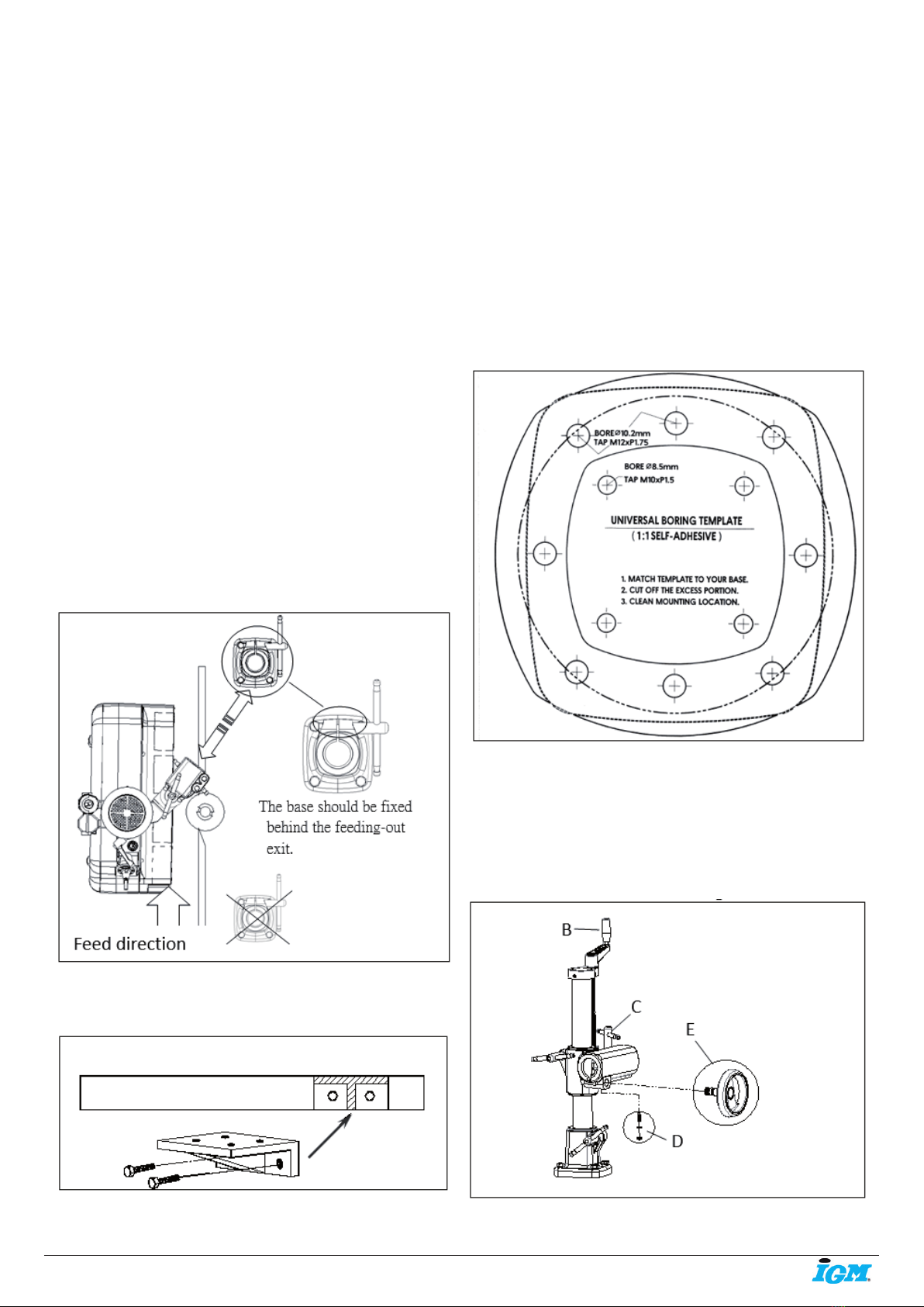
5.4 Installation Steps
NOTE: Ensure there is sucient weight support to
prevent power feeder tilted while Swing aside.
1. Conrmation of Power Feeder stand base
mounting position:
For small machine table, an extension bracket (no
provided) is recommended.
2. Locate boring position
For your boring convenience and accuracy, a SCALE
1:1 SELF-ADHESIVE DRILLING TEMPLATE is provided
and enclosed in the package.
Clean location free from oil. Tape SELF-ADHESIVE
DRILLING TEMPLATE to desire position. Mark it
with centre punch; Avoid table rib and support
underneath the table.
Prepare 4 sets of M12 bolts & spring washers (not
provided).
5.5 Assembling
NOTE: Get help! Feeder is heavy. Do not try to do it
on your own.
Fasten base to table attached with 4 sets of M12
screws, spring washer.
Insert “STAND” to BASE. Assemble Handle.

-6-www.igmtools.com
Operating instructions EN
Insert OVER-ARM into ELEVATING-BRACKET. Turn
wheel a few turns. Tighten LEVER.
Insert the extension tube (A) into cross slide vise,
push (B) hand-wheel into cross slide vise and
rotating while push-in, ensure the hand-wheel kit are
intermeshing with extension tube kit properly.
Lock the headless hex-screw in to cross slide vise
(C), the rotating the handle-wheel and insert it into
hand-wheel gear groove (D) to ensure the gears can
be rotating smoothly, lock the hex-screw to complete
the installation.
Install control-joint: To slip the end side of the
extension tube into swivel cone (A) and ensure the
alignment of the lever and extension tube centre line
(C) lock with 2 attached screw. (B)
NOTE: The parallelism of the feeder rollers can be
aected by the angle of swivel cone.
Adjust the motor suspension: Loosen the lever(A) to
push motor suspension to the left side of the table
horizontally.
NOTE: Motor suspension level can stable the feeder
and parallel to the worktable.
Power switch positioning: Due to the packaging and
shipping consideration, the power switch was placed
aside. Loosen the attached 4 Hex screw to move the
motor to the front for more convenient operation.
Machine body installation: Loosen the hex-screw(A)
and quick release grip (B), and take o the motor
clamp.

-7-www.igmtools.com
Operating instructions EN
Conrmation:
• Locked the hex-screw (A) and quick release handle
grip (B) to even the gap of two end. Loosen the quick
release lever to rotate the machine body.
• Feeder angle adjustment, Loosen the stand handle
(A) and lower the feeder to adjust the rollers and
worktable until them horizontally.(B)
• Feeder roller level positioning: Lower feeder to table,
alignment“slight o”is acceptable.
- oset by indendent suspension.
• Loosen the handle grip (A), adjusting the motor
suspension level (B)
• Loosen two attached screws(C), and adjust the
motor suspension angle (D).
To complete the installation: Conrm all the handle
and screws are locked properly.
6. OPERATION CONTROL
6.1 Stand
Over-Arm rotation: Loosen lever. (A)
Over-Arm extension: Loosen Lever (B),
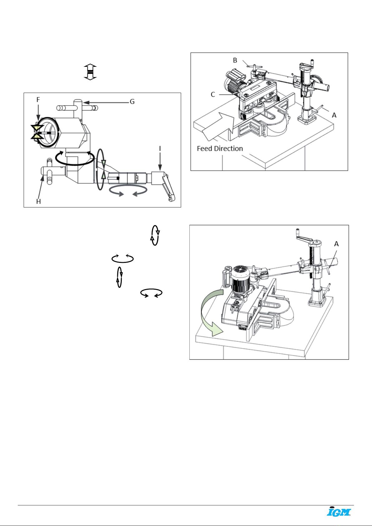
-8-www.igmtools.com
Operating instructions EN
rotate side-wheel. (C)
Over-Arm elevation: Loosen Lever (D), rotate
TOP-Wheel. (E)
6.2 Control- Joint
Arm-bracket: Loosen 2 attached screws (F)
Angle Joint: Loosen Lever (G)
Motor clamp: Loosen Lever (H)
Machine body: Loosen quick release (I)
6.3 Feeding
Loosen Level (A), then swing the feeder aside then
locked the lever til tight
NOTE: Ensure there is sucient weight support to
prevent power feeder tilted while Swing aside.
Loosen LEVER (B), rotate the machine to left side 90°
(vertical to the ground), rollers faced to right, motor
to left then lock the lever.
Loosen LEVER (C), rotate the machine 90° (Parallel to
the ground) power switch on top, roller at the bottom
the lock the lever.
Loosen LEVER (A), push the machine back to
worktable, postion the roller opposite to the guide
plate then lock the lever.
Lock all ther lever properly to complete the
adjustment.
NOTICE: The purpose of elevating kits tolerance gap is
to allow smooth operation while elevating the feeder;
Please pull back machine body to feed-in direction
after elevating adjustment and lock the hand lever to
tight at the meantime (A).
7. POWER CONNECTION AND GROUNDING
NOTE: Read the motor specication to ensure
thepower source and voltage is compatible. (Range:
±5%)
Ensure power switch is (OFF) before connect the
power source.
Requirement:
• Connected to the repectively non-fuse circuit or
motor circuit breaker.
• The external power switch cord cannot be less than
12AWGl.
• Switch required wired in compliance with your
national or local electrical regulation.

-9-www.igmtools.com
Operating instructions EN
Using the extension cable if needed: 30M or under
using 12AWG cable, 46M or above using 10AWG
cable.
Ensure all the grounding wires connected properly;
impropriate connection may cause the damage to the
motor.
Ensure the groupding wire of the motor (green
or yellow) connected techinician for any further
assistance.
Please contact professional technician for any further
assistance.
Rated current reference:
• 34/38/44/48/04/MX

-10-www.igmtools.com
Operating instructions EN
8. SPEED CONTROL
Notice: cut out the power before adjustment
Appropriate feeding speed rate and well sharped
cutting blade can cause the procedure process quality
and eciency.
Determinate the correct feeding speed by the
hardness of the work-piece, material and the desired
cutting procedure.
Listen attentively while feeder rotating and re-check
the sample after procedure process then adjust
setting to desired result.
Maintain the cutting blade and keep it sharpe all the
time.
Speed shifting: Cut out the power before shifting.
Rotate the rollers while switch the speed to allow the
clutch and derailleur get engaged properly.
Derailleur and gear settle
• Model 34/44/04
(A) +Derailleur control(Fig 16-1)
• Model 38/48 (3PH)
(A) +(C)+ Derailleur control (Fig 16-2)
• Model 38/48 (1PH)
(B) +(C)+Derailleur control (Fig 16-2)
• Model MX
(A) +Derailleur(Fig 16-3)

-11-www.igmtools.com
Operating instructions EN
Gear replacement instruction.
Loosen two attached screws to take o the cover.
Loosen the Hex screw to replace the gear set.
NOTE: The hub of the gear should be turned inward to
avoided possible interference.
NOTE: Optional gear set available
34/44/04/54 model speed(4+4=8)
38/48/68model speed(8+8=16)
9. Roller replacement
Notice: cut o the power source before operation.
Loosen 2 attached M8 screws.
Replace with brand new rollers then tighten the
screws to complete the replacement.
Notice: Conrm all the screws are locked properly
after rst operation.
The rubbers have been tested by high standard QC
control and durability test.
• Its traction friction and durability is incomparable
to other brands. Please replace with Co-matic made
Roller.
10. MAINTENANCE
Notice: Cut o the power source before operation.
Rollers:
Grease rollers and chains every 200 hours or 30 days
through ttings by using grease gun.
Chain wheel and chain should be maintained
regularly.
Recommended Grease:
• SHELL Alvania (SHELL Alvania R. 2);
• (SHELL GADUS S2 V220 2);

-12-www.igmtools.com
Operating instructions EN
• (MOBILUX EP 2);
• (FUCHS RENOLIT EP 2);
• (BP ENERGREASE MM-EP 2)
Turbine oil:
Exchange turibine oil rst 200 hours of 30 day while
rst starts the machine. Change oil after 1000 working
hours or 90 days after purchase of new feeder.
Using same brand of turbo oil or equivalent oil as
following:
• MOBIL - MOBILGEAR 630;
• SHELL - OMALA 150;
• BP - ENGERGOL GR-SP 150
Turbine oil replacement:
Refer to page 7: operation and adjustment please pay
attention to the balance of the feeder and worktable
while moving the feeder aside, then ip it over and
open the oil plug to allow the oil ow out, follow the
instruction to ll up the turbo oil.
Turbine oil lled up standard
• 38/48 300CC (38mm, 1-1/2“)
• MX 200CC (38mm, 1-1/2“)
Using wind gun to maintain the feeder after every
operation.
Model MX: Using tool to pry open inside of dust
collector ; Please seal up with tape while not in use.
11. FEEDER OPERATION INSTRUCTION
Jointer operation:
• Rollers & cutting blade:
Pic. 11-1
• Feeder position & guiding plate:

-13-www.igmtools.com
Operating instructions EN
Pic. 11-2
• Feeding pressure & Work-piece:
Pic. 11-3
Table-saw operation:
• Rollers & cutting blade:
Pic. 11-4
• Feeder position & guiding plate (pic. 11-2).
• Feeding pressure & Work-piece (pic. 11-3).
Manual operation
• Rollers & cutting blade:
• Feeder position & guiding plate (pic. 11-2)
• Feeding pressure & Work-piece: light pressure.
NOTE: The space between feed-in rollers and the
guide plate sould be at least 3~5mm wider than
Feed-out rollers to ensure the roller can fully cover
and give enough presssure to the work-piece.

-14-www.igmtools.com
Operating instructions EN
12. MX48B HOUSING ASSEMBLY
-15-www.igmtools.com
Operating instructions EN
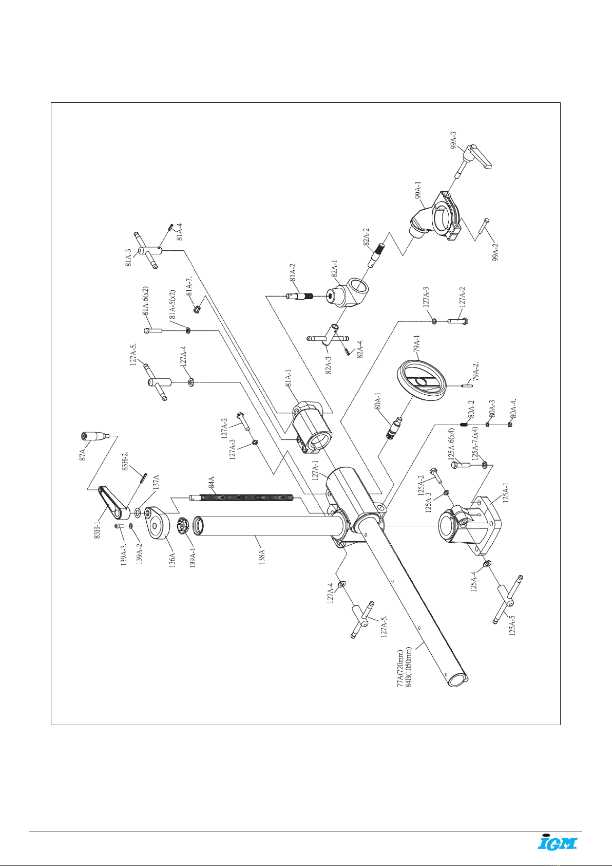
HEAVY-DUTY UNIVERSAL STAND ASSEMBLY

IGM nástroje a stroje s.r.o., Ke kopanině 560,
Tuchoměřice, 252 67, Czech Republic, E.U.
+420 220 950 910,www.igmtools.com
© 2022 IGM nástroje a stroje s.r.o.
Operating instructions EN
Part No. Code No. Description QTY
B076203 B076203 Bearing 1
02G 02G Housing Frame Kit 1
02G-1 C020037 Housing Frame 1
02G-2 A500302 Bushing 4
02G-3 A500301 Bushing 1
02G-4. A500347 Bushing 4
03A 03A Roller Supporter Kit 4
03A-1 C020333A Roller Supporter 1
03A-2 A500309 Sprocket 1
03A-3 S060616 Cap Screw 2
03A-4. S060840 Cap Screw 2
03G 03G Sprocket Case Kit 4
03G-1 C020349A Sprocket Case 1
03G-2 N950004 Spring 1
03G-3 A500359 Bushing 1
03G-4. U010052 Case Cap 1
04A K330026 Chain 4
04G 04G Sprocket Shaft Kit 3
04G-1 G320023 Sprocket Shaft 1
04G-2 T315106 Grease Nipple 1
04G-3. N510015 Snap Ring 1
05G 05G Main Sprocket Shaft Kit 1
05G-1 G320025 Main Sprocket Shaft 1
05G-2 T315106 Grease Nipple 1
05G-3 N011225 Flat Washer 1
05G-4. N11012H Nut 1
06G 06G Roller Spindle Kit 4
06G-1 T315106 Grease Nipple 1
06G-2 G320028 Roller Spindle 1
06G-3 N030012 Spring Washer 1
06G-4 N510020 Snap Ring 1
06G-5. S601250 Hex Screw 1
07G A500308 Bushing 4
08G C120005 Worm Gear 1
09G C120011 Worm Gear 1
10G 10G Worm Gear Shaft Kit 1
10G-1 G320026 Wormgear Shaft 1
10G-2 K420612 Key 1
10G-3 N011225 Flat Washer 1
10G-4. N11012H Nut 1
12G 12G GEAR SET 1
12G-1 A500344 Gear 1
12G-2. A500345 Gear 1
14G U010078 Housing Cover 1
15G U010087 Knob 2
16G U010014 Brush 2
18G 18G Roller Cover Kit 1
18G-1 U010080 Roller Cover 1
18G-2. S500512 PH. Screw 4
21A 21A Oil-Cap Kit 1
21A-1 U010008 Oil Cap 1
21A-2. Q010012 "O" Ring 1
27A 27A Transmission Kit 1
27A-1 A500303 Sprocket 2
27A-2 K330040 Chain 2
27A-3 A500307 Double-Sprocket 4
27A-4. K330062 Chain 1
35A 35A Gear Kit 1
35A-1 A500310 Gear 1
35A-2. A500311 Gear 1
45M1 45M1 Motor w/ Switch 1
45M3 45M3 Motor w/ Switch 1
46A 46A Switch Box 1
47A 47A Switch Kit 1
114G 114G Wormgear Box Cover Kit 1
114G-1 Q010065 "O" Ring 1
114G-2 C020350 Wormgear Box Cover 1
114G-3 Q021701 Oil Seal 1
114G-4. S060616 Cap Screw 3
RO121 RO121 Roller tire 4
Part No. Code No. Description QTY
77A E580002A Over Arm Kit 1
79A 79A Handwheel Kit 1
79A-1 U010082 Handwheel 1
79A-2. N810636 Lock Pin 1
80A 80A Pinion Kit 1
80A-1 G020001 Pinion 1
80A-2 G000007 Screw 1
80A-3 N030008 Spring Washer 1
80A-4. N11008R Nut 1
81A 81A Over Arm Cone Kit 1
81A-1 A250403 Over Arm Cone 1
81A-2 G020005 Stud 1
81A-3 G020007A Handle 1
81A-4 N810622 Lock Pin 1
81A-5 N030010 Washer 2
81A-6 S601050 Screw 2
81A-7. U010119 Cord Sheath 1
82A 82A Swivel Cone Kit 1
82A-1 A200304 Swivel Cone 1
82A-2 G020005 Stud 1
82A-3 G020007A Handle 1
82A-4. N810622 Lock Pin 1
83H 83H Handle Kit 1
83H-1 U010139A Handle w/ Bushing 1
83H-2. N810636 Lock Pin 1
84A G320090 Elevating Screw 1
84B E580003A Over Arm Kit 1
87A U010011 Handle-Grip 1
99A 99A Motor Clamp kit 1
99A-1 A200305 Motor Clamp 1
99A-2 S600850 Screw 1
99A-3. T060003 Pull Handle 1
125A 125A Base Kit 1
125A-1 A250401 Column Base 1
125A-2 S601275 Hex Screw 1
125A-3 N050012 Lock Washer 1
125A-4 N011225 Washer 1
125A-5 G020010A Handle 1
125A-6 S601250 Hex Screw 4
125A-7. N030012 Spring Washer 4
127A 127A Elevating Bracket Kit 1
127A-1 A250402 Elevating Bracket 1
127A-2 S601275 Hex Screw 2
127A-3 N050012 Lock Washer 2
127A-4 N011225 Washer 2
127A-5. G020006A Handle 2
136A C020110A Column Cape 1
137A G150031 Washer 1
138A E580013A Vertical Column Kit 1
139A 139A Fastener Kit 1
139A-1 U010279 Fastener 1
139A-2 N015816 Flat Washer 1
139A-3. S900825 Cap Screw 1
MX48 HOUSING PARTS LIST HEAVY-DUTY STAND PARTS LIST
Table of contents
Other IGM Industrial Equipment manuals

Popular Industrial Equipment manuals by other brands


FLENDER
FLENDER FASTEX IC220 Assembly and operating instructions

Venmar
Venmar AVS HRV EKO 1.5 quick start guide

Zimmer
Zimmer GPH8000 Series Installation and operating instructions

Toshiba
Toshiba CV-10HB instruction manual

ABB
ABB HT846542 Operation manual

Siemens
Siemens SIRIUS 3RH21 Series Original operating instructions