IGM 141-DC30 User manual

Distributor:
IGM nástroje a stroje s.r.o.
Ke Kopanině 560, 252 67, Tuchoměřice
Czech Republic, EU
Phone: +420 220 950 910
E-mail: [email protected]
Website: www.igmtools.com
Easy power feeder
Operationg instructions
2022-07-11
141-DC30,DC40 IGM Easy Power Feader Manual EN v2.7.00 A4ob
141-DC30,DC40
www.igmtools.info
PDF ONLINE

-2-www.igmtools.com
Operating instructions EN
Please read this manual thoroughly and follow the safety instructions in it! Technical changes
and printing errors reserved!
Dear customer,
This manual contains important instructions and information for the installation and proper use of
DC30 and DC40 Power feeders.
This manual is a part of the machine and therefore it should not be kept elsewhere than in the vicinity
of the machine so that you can be consulted at any time by you or other persons operating the
machine.
Please read and follow the safety instructions!
Carefully read these instructions before using the machine. Operation of the machine will
be simpler and you will also lower the risk of injury while eliminating the probability of
incorrect operation and possible damage to the machine. Because of our policy of constant
improvement, the design, construction or pictures may differ slightly. Should you discover
1. DECLARATION OF CONFORMITY
The undersigned: IGM nástroje a stroje s.r.o.
Address: Ke Kopanině 560
Tuchoměřice, Praha-západ, PSČ 252 67
Czech Republic, EU
Tel. +420 220 950 910
Certifies
Product: Power Feeder
Model: DC30 and DC40
Manufacturer: CO-MATIC Machinery Co., Ltd.,No.
473-16,
San Feng Road, Houli District, Taichung
City,Taiwan, R.O.C. 42156
We declare under our sole responsibility that the
product described in this manual is in conformity
with the following standards: EN ISO 12100, EN ISO
13857, EN 349, EN 953, EN 60204-1, EN ISO 11202,
TABLE OF CONTENTS page
1. DECLARATION OF CONFORMITY 2
2. WARRANTY SERVICE 3
3. SAFETY INSTRUCTIONS 3
3.1 Notice 3
3.2 General safety instructions 3
3.3 Risks 4
3.4
Important notice
4
3.5
Safety rules
4
4. SPECIFICATIONS OF THE MACHINE 4
4.1 Machine description 4
4.2 Technical data 4
4.3 The package includes 4
5.
TRANSPORT, UNPACKING AND ASSEMBLY
5
5.1 Transport and unpacking 5
5.2 Assembly 5
5.2.1 Fastening to a machine 5
5.2.2. Assembly 5
5.3 Electrical connection 6
6. SETUP AND ADJUSTMENT 6
6.1 Basic movements of the feeder 6
6.1.1 Feeding from the side 6
6.1.2 Feeding at an angle 6
6.2 Control panel features 7
7. OPERATING THE MACHINE 7
8. MAINTENANCE AND CONTROL 7
8.1 Replacing rollers 7
8.2 Greasing 7
8.3 Transmission fluid replacement 8
9. MALFUNCTION ASSISTANCE 8
9.1 Error messages 8
10. PROTECTION OF THE ENVIRONMENT 8
11. ACCESSORIES SPARE PARTS 8

-3-www.igmtools.com
Operating instructions EN
EN 55014-1, EN 55014-2 podle s ustanoveními
směrnic 2006/42/EC, 2004/108/EC, 2006/95/EC,
2002/95/EC.
Signed: Ivo Mlej
Managing Director
2. WARRANTY SERVICE
The warranty is subject to Terms and Conditions and
Warranty Conditions of IGM nástroje a stroje s.r.o.,
the current version of which are available at www.
igmtools.com.
3. SAFETY INSTRUCTIONS
3.1 Notice
This machine is designed for work with wood and
wooden materials.
Proper use also includes compliance with the regular
operational and maintenance work described in this
manual.
The machine can be operated only by persons
familiar with the operation procedures, maintenance
and are aware of potential risks involved.
Comply with the minimum age limits specified by
law. The machine may only be used when in perfect
technical condition.
All safety and protective components must be
installed when operating the machine.
Besides these instructions, also adhere to the safety
instructions of your country and to the generally
recognized technical practices concerning the
operation of woodworking machinery.
The manufacturer or the supplier is not responsible
for any damage resulting from improper use.
Every user is responsible for their own actions.
The warranty cannot be claimed if any of the
following principles are broken:
- Unsuitable work environment: high humidity,
contamination.
- Damage caused by an improper assembly and/or
improper storage.
- Use of damaged machinery.
- Failure to follow the operating instructions:
transport, storage, assembly, putting into operation,
cleaning and maintenance of the machine.
- Use of unauthorized spare parts.
3.2 General safety instructions
The machine can pose danger when improperly
operated.
Completely read the operating instructions before
working with the machine and follow all the
instructions in this manual.
Keep this user manual clean and protect it from dirt
and moisture; in case of re-selling, pass the manual
onto the new owner.
Any alterations or changes to the machine are
prohibited.
Daily try out if the machine runs smoothly and check
the function of protective covers before operating the
machine. Replace any deficiencies and immediately
remove any damaged parts like covers.
The machine may only be used when in perfect
technical condition.
Use a hairnet or a hat to protect long hair. Wear tight-
fitting clothes, remove all bracelets, rings, necklaces or
ties. Wear work boots only, do not wear casual shoes
or sandals during work. Abide by the regulations for
personal protection.
Always wear safety eyewear. Always use hearing
protection. The tools are sharp and can cause severe
injury, use them with care.
Keep in mind the necessary space for operation when
installing and positioning the machine. The machine
must stand on a stable surface and must be adequately
lit.
Always use respiratory protection when working in a
dusty environment.
Make sure you have good lighting.
Make sure the power cord is not in your way when
working. Keep your work area clean. Never touch the
machine when it‘s running.
Make sure you are concentrating and paying attention.
Use caution. Never work under the influence of drugs
and/or alcohol.
Make sure there are no children around when working
with the machine.

-4-www.igmtools.com
Operating instructions EN
4. SPECIFICATIONS OF THE MACHINE
4.1 Machine description
1
2
3
5
6
78
9
10
11
12 14
13
15
17
16
4
pic.1
Never leave the machine unattended. Always switch
the machine off when leaving the workspace.
Watch your fingers and other body parts when
working. Never walk away from a machine without
protective guards.
Do not place anything on the machine.
Electrical connections malfunctions can be repaired
by an electrician only. Damaged electric cord must be
replaced immediately.
Any adjustments and maintenance may be carried out
when the machine is disconnected from the power
source.
3.3 Risks
Risks may arise even during proper and prescribed use
of the machine.
The danger of a workpiece flying off. Beware of noise
and dust.
Wear eye, ear and dust protection.
Use a suitable dust extraction device! Watch out for
damaged electrical cords.
3.4 Important notice
Only use the feeder in an appropriate environment.
Keep your workspace well ventilated and lighted,
avoid wet or damp environments.
Only operate the machines under temperatures
ranging from +5°to +40°C. Humidity from 30% to 95%.
3.5 Safety rules
The tool must reach working speed before feeding.
Do not overload the machine by feeding material too
quickly.
ALWAYS keep your hands away from rotating parts.
Provide additional support and stability for larger
workpieces.
Always switch off the feeder first, only then switch off
the machine that is being fed material.
Always disconnect the power cord before any repairs
or adjustments.
1 base
2 locking lever (turning)
3 height-adjustable arm 4 locking lever (height
adjustment)
5 stand
6 height control (turning alters height) 7 locking lever
(protrusion)
8 feeder arm
9 screws (positioning joint) 10 locking lever (turning)
11 locking lever (angle of the feeder)
12 angle locking pin 13 control display
14 motor
15 control wheel of arm protrusion (turning moves
the arm)
16 feeder grip
17 roller
4.2 Technical data
Type DC30 DC40
Motor power (400V) 500W 500W
Arm reach 460mm 460mm
Max. workpiece height 250mm 250mm
No. of rollers 3 4
Size of rollers 120x60mm 120x60mm
Feed speed 2-22m/min 2-22m/min
Weight with stand 53kg 56kg
4.3 The package includes
feeder
feeder stand arm
quick adjustment joint
plan for base drilling 1:1 manual
-5-www.igmtools.com
Operating instructions EN
5. TRANSPORT, UNPACKING AND ASSEMBLY
5.1 Transport and unpacking
The machine is not assembled due to transport.
Remove the feeder from the packaging and place
on a flat surface. Check for any apparent transport
damages, these could damage the machine or your
health.
5.2 Assembly
We recommend to greasing the metal parts before
assembly.
5.2.1 Fastening to a machine
- Mounting the base. The feeder is supplied with a 1:1
template that facilitates the mounting of the feeder
onto a base.
1. Unpack the feeder base and adjust it according to
the mounting template.
opening on the side of the arm (8.1, pic.7). Insert the
cable into the sleeve up to the double insulation.
It‘s necessary to take the cable apart from the
terminal plate - Only an electrician with a proper
permission is allowed to do that. Mount the joint
end and so far tighten only with one screw.
De-grease the surface with rubbing alcohol and put
TAP
M12 x P1.75
BORE 10.3-10.5mm
BORE 8.5-8.7mm
UNIVERSAL BORING TEMPLATE
TAP
M10 x P1.5
(1:1
SELF-ADHESIVE
)
1.
MATCH TEMPLATE TO YOUR BASE
。
2.
CUT OFF THE EXCESS PORTION
。
3.
CLEAN MOUNTING LOCATION
。
SCREWS NOT INCLUDED
F
F
Heavy Duty
pic.2
2. Prepare 4 bolts and spring washers (not included).
Bolt size - M10, length = feeder base (thickness) +
table top (thickness)
3. Select position of the base to avoid ribbing on the
bottom of the table.
5.2.2. Assembly
- Fasten the base of the feeder to the table top using
four M12 bolts, place the stand into the base. Screw
the handle into the lever using the nut under the
handle.
(Obr. 4)
4-M12
pic.3
(Obr. 5)
pic.4
(Obr. 6)
1
2
3
4
pic.5
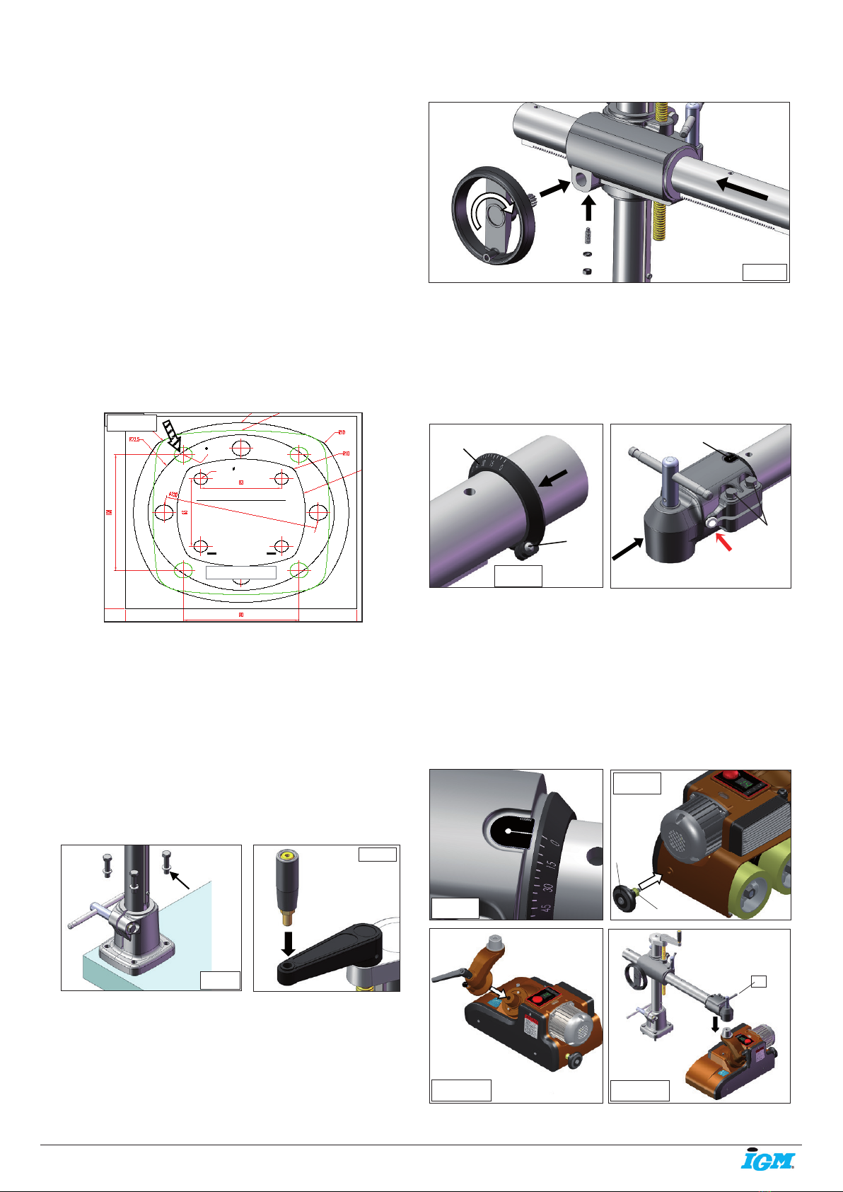
Insert the arm (1, pic.5) into the height-adjustable
holder. Mount the control wheel 4 so that the pinion
2 fits into the teeth of the feeding comb. Screw the
locking screw 3 from the bottom side and tighten
with a contra nut against the screw.(pic.5) Insert the
scale ring (R, pic.6) on the arm of the feeder and slide
further away from the edge. Insert the cable into the
(Obr.
7)
M4
R
pic.6
(Obr. 8)
S
8.1
pic.7
2
on the sticker with a scale (S, pic.7 and 8).
Mount the handle (1, pic.9) into the feeder but
don‘t tighten too much, it should rotate. Mount the
positioning joint onto the pin on the feeder and
screw in using the locking lever. (pic.10)
Place the feeder on your workbench. Move the joint
end towards the pin screwed into the arm. Mount
on the pin and tighten the locking lever (1, pic.11).
Tighten the screws on the joint ending (2, pic.7).
(Obr. 10)
1
2
pic.9
(Obr. 9)
pic.8
pic.10 pic.11
1

-6-www.igmtools.com
Operating instructions EN
5.3 Electrical connection
WARNING: Make sure the electrical connection
corresponds to the motor specification (see engine
cover.) WARNING: Make sure the switch is in the
„OFF“ position before turning on the feeder.
A power feeder is an auxiliary machine that
cooperates with your spindle moulder, table saw or a
planer.
If you need to use an extension cord; use a 18AWG x
4C when not exceeding 5 metres and a 16AWG x 4C
when over 5 metres.
6. SETUP AND ADJUSTMENT
- Place a 3-4 mm high pad under the output roller
and slowly run the feeder down until the input roller
lies on the surface and the output roller is touching
the pad. Now tighten the screws (K, pic.13) and set
the scale ring to zero. Tighten the locking pin (H), this
secures stronger downforce on the infeed roller.
6.1 Basic movements of the feeder
6.1.1 Feeding from the side
- Release the locking lever (A) and turn the feeder off the
workbench.
- Release the lever (H), grab the handle of the feeder and
lift the locking pin, turn the feeder to a vertical position.
Turn it back on the workbench and tighten all the levers.
- The workpiece must be leaning on a guiding fence
when feeding. The rollers must push the workpiece
against the fence. The difference between the distance
of the feeder and the fence should be greater on the
infeed roller by 3-4 mm than on the outfeed roller (pic.
15).
6.1.2 Feeding at an angle
- Release the locking lever (A) and turn the feeder off the
workbench.
- Release screws (K) on the end of the arm, turn the
positioning joint and set up the required angle (S), and
then tighten screws (K). (pic.13)
- Release levers (F and G), pull out the locking pin and
align the feed so that all rollers are in the same height
over the workbench, then tighten all the levers (pic. 14).
- The workpiece must be leaning on a guiding fence
when feeding. The rollers must push the workpiece
against the fence. The difference between the distance
of the feeder and the fence should be greater on the
infeed roller by 3-4 mm than on the outfeed roller (pic.
15).
pic.12
1
- For rotation around the axis of the base:
release lever (A), and turn the feeder to the
requested position.
- To extend or compress the arm of the
feeder: release the lever (B) and
rotate (C).
- To alter the height: release the lever (D)
and turn the handle (E).
- To rotate the feeder: release the lever
(F) and turn the whole feeder.
- To adjust the angle of the feeder: release
lever (G). Pull out the locking pin (H) and
use a handle (1, pic.9) to turn the feeder.
G
F
Obr. 19
pic.14
Obr. 20
X+3~4mm
X
podávání
pic.15
pic.13
-7-www.igmtools.com
Operating instructions EN
6.2 Control panel features
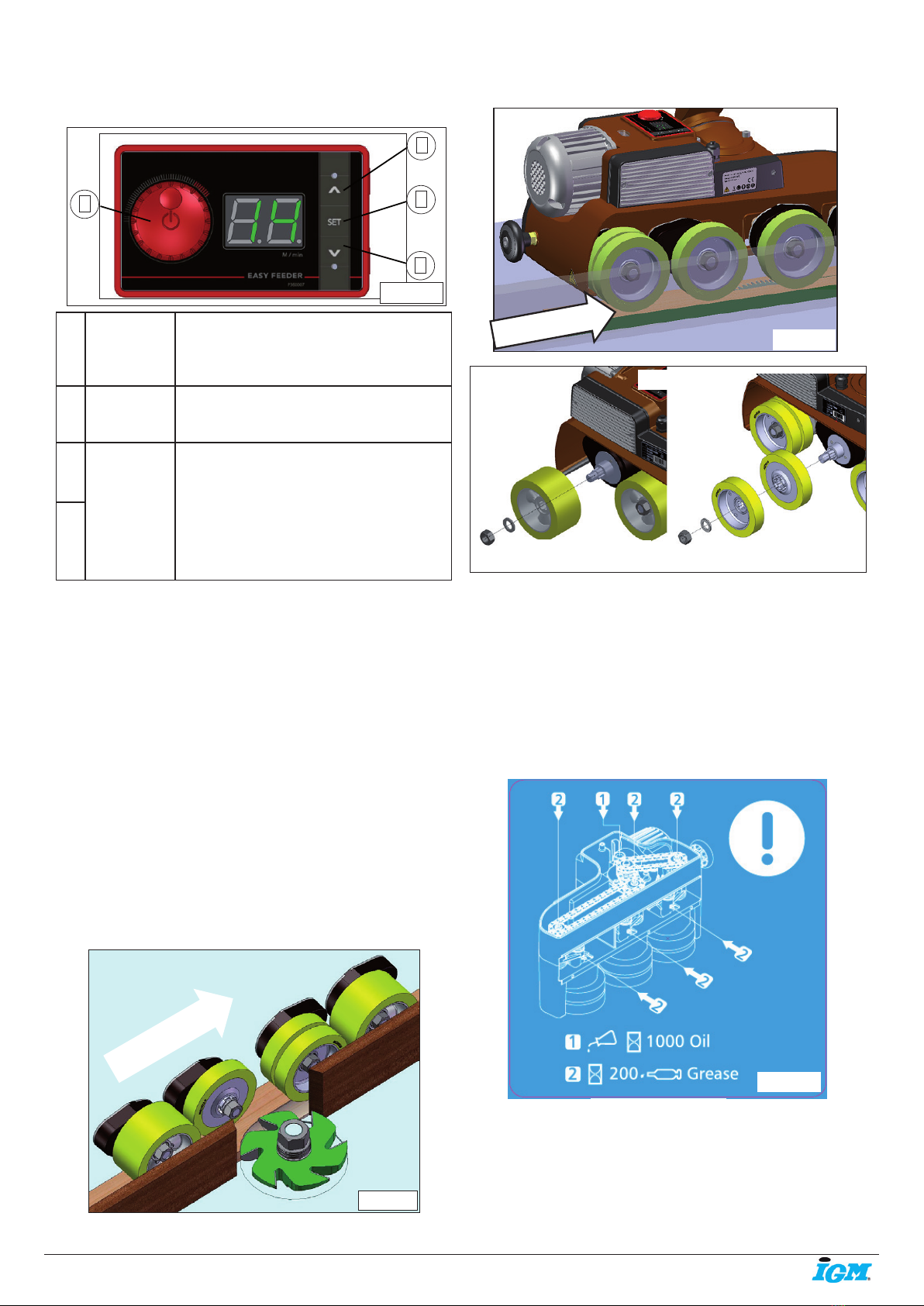
8.2 Greasing
- The wheels and chains should be greased every 200
hours or 30 days using a grease gun, see section 2, the
location of grease on the displayed label (pic.20).
- Gears and chains: grease regularly.
- Recommended greases: (Shell – Alvania Grease
R2, SHELL GADUS S2 V220 2, MOBILUX EP 2; FUCHS
RENOLIT EP 2; BP ENERGREASE MM-EP 2
and other)
1. Vypínač
s nastavení
m rychlosti
3. Tlačítko směru podávání
2. Tlačítko nastavení
4. Tlačítko směru podávání
1
3
2
4
pic.16
1
Switch
and feed
speed
Speed in the range of 2-22 m/min
Press to turn the feed on and off
2Settings
button
Press to set up the desired feed
speed
3Feed
direction
button
Change of feed direction during
work: press the direction button
twice. The opposite direction will
run at the lowest speed. Press the
on/off switch twice for the original
setting.
4
7. OPERATING THE MACHINE
After switching the machine on, let the feeder reach
its full speed before feeding any material.
8. MAINTENANCE AND CONTROL
8.1 Replacing rollers
- You can choose out of two types of rollers:
Ø120 x 60 mm (141-R12060) and
Ø120 x 25 mm (141-R12025).
- The outfeed roller can be removed when working
with larger routers (pic.17).
- The infeed roller can be removed to avoid contact of
the saw blade with the feeder (pic.18).
- Use various roller combinations for different
conditions and operations.
pic.17
feed direction
pic.18
feed direction
Sada kol
Jedno kolo
pic.19
Obr. 24
pic.20
One roller Set of rollers

IGM nástroje a stroje s.r.o., Ke kopanině 560,
Tuchoměřice, 252 67, Czech Republic, E.U.
+420 220 950 910,www.igmtools.com
© 2022 IGM nástroje a stroje s.r.o.
Operating instructions EN
8.3 Transmission fluid replacement 9. MALFUNCTION ASSISTANCE
9.1 Error messages
E1 - Motor will not start: Check that there isn‘t
anything stuck in the feeder.
E2 - Drive mechanism temperature is too high.
E3 - Engine temperature is too high.
• After removing a probable malfunction - restart the
main switch.
• If you are not sure why a problem occurred, please
contact technical support.
10. PROTECTION OF THE ENVIRONMENT
Protect the environment.
Your machine contains materials that can be recycled.
Please, let specialized institutions handle the
machine.
11. ACCESSORIES SPARE PARTS
IGM Spare roller D120x60 for DC30-DC40 Feeders
141-R12060
IGM Narrow spare roller D120x25 for DC30-DC40
Feeders
141-R12025
IGM Swivel Cone Kit 0 - 90° set for Feeders DC30-DC40
141-KS
- Oil change after 200 hours of operation (30 days)
of a new machine. Afterwards, replace oil every 1000
hours (6 months). The mentioned horizon is based on
the assumption of an everyday 8-hour service.
- The oil indicator is next to the display. Put the feeder
to the displayed position (see pic.22) to see the oil
status.
- Rotate the feeder away from your workbench into
free space, open the cover, turn the feeder upside
down, release the oil cap and let some oil out. When
all the oil is gone, place the feeder to a vertical
position and pour in the transmission fluid according
to the oil indicator.
- Recommended gear oil: MOBIL Mobilgear 630,
Shell/Omala 150 BP, Energol GR-XP 150, and other
equivalents.
- Clean the machine after every use (dust, shavings
etc.).
Obr. 25
pic.21
Obr. 26
pic.22
This manual suits for next models
1
Table of contents
Other IGM Industrial Equipment manuals

Popular Industrial Equipment manuals by other brands


MyBinding
MyBinding SealerSales KF-300F instruction manual

Thomas
Thomas SAR 460 SA G DIGIT Use and maintenance manual

Graco
Graco HIGH-FLO Viscount II 300 Series Instructions-parts list

Vaughan
Vaughan ROTAMIX SYSTEM Installation, operation & maintenance instructions

Festo
Festo EGC-TB-KF operating instructions

Vahle
Vahle SMGM-BCC System manual

Manntek
Manntek DCC operating manual

Cee
Cee 1300CSX Operator user manual

RAMMER
RAMMER S 83 STD Operation and maintenance manual

Utile
Utile 700 Series Installation, operation & maintenance instructions

Allied Systems
Allied Systems LONG REACH CCHA Installation maintenance and service manual

Clemco
Clemco SCW-2048 owner's manual