Advantech iDAQ-731 User manual

User Manual
iDAQ-731, iDAQ-751,
iDAQ-763D
Digital I/O and Relay Industrial
DAQ Modules

iDAQ-731_751_763D User Manual ii
Copyright
The documentation and the software included with this product are copyrighted 2021
by Advantech Co., Ltd. All rights are reserved. Advantech Co., Ltd. reserves the right
to make improvements in the products described in this manual at any time without
notice. No part of this manual may be reproduced, copied, translated, or transmitted
in any form or by any means without the prior written permission of Advantech Co.,
Ltd. The information provided in this manual is intended to be accurate and reliable.
However, Advantech Co., Ltd. assumes no responsibility for its use, nor for any
infringements of the rights of third parties that may result from its use.
Acknowledgments
Intel and Pentium are trademarks of Intel Corporation.
Microsoft Windows and MS-DOS are registered trademarks of Microsoft Corp.
All other product names or trademarks are properties of their respective owners.
Product Warranty (2 years)
Advantech warrants the original purchaser that each of its products will be free from
defects in materials and workmanship for two years from the date of purchase.
This warranty does not apply to any products that have been repaired or altered by
persons other than repair personnel authorized by Advantech, or products that have
been subject to misuse, abuse, accident, or improper installation. Advantech
assumes no liability under the terms of this warranty as a consequence of such
events.
Because of Advantech’s high quality-control standards and rigorous testing, most
customers never need to use our repair service. If an Advantech product is defective,
it will be repaired or replaced free of charge during the warranty period. For out-of-
warranty repairs, customers will be billed according to the cost of replacement mate-
rials, service time, and freight. Please consult your dealer for more details.
If you believe your product is defective, follow the steps outlined below.
1. Collect all the information about the problem encountered. (For example, CPU
speed, Advantech products used, other hardware and software used, etc.) Note
anything abnormal and list any onscreen messages displayed when the prob-
lem occurs.
2. Call your dealer and describe the problem. Please have your manual, product,
and any helpful information readily available.
3. If your product is diagnosed as defective, obtain a return merchandise authori-
zation (RMA) number from your dealer. This allows us to process your return
more quickly.
4. Carefully pack the defective product, a completed Repair and Replacement
Order Card, and a proof of purchase date (such as a photocopy of your sales
receipt) into a shippable container. Products returned without a proof of pur-
chase date are not eligible for warranty service.
5. Write the RMA number clearly on the outside of the package and ship the pack-
age prepaid to your dealer.
Part No. 2001073100 Edition 1
Printed in China November 2021

iii iDAQ-731_751_763D User Manual
Declaration of Conformity
CE
This product has passed the CE test for environmental specifications when shielded
cables are used for external wiring. We recommend the use of shielded cables. This
type of cable is available from Advantech. Please contact your local supplier for
ordering information.
Test conditions for passing also include the equipment being operated within an
industrial enclosure. In order to protect the product from damage caused by electro-
static discharge (ESD) and EMI leakage, we strongly recommend the use of CE-
compliant industrial enclosure products.
FCC Class A
This equipment has been tested and found to comply with the limits for a Class A dig-
ital device, pursuant to part 15 of the FCC Rules. These limits are designed to pro-
vide reasonable protection against harmful interference when the equipment is
operated in a commercial environment. This equipment generates, uses, and can
radiate radio frequency energy and, if not installed and used in accordance with the
instruction manual, may cause harmful interference to radio communications. Opera-
tion of this equipment in a residential area is likely to cause harmful interference. In
such cases, users are required to correct the interference at their own expense
警告使用者
這是甲類測試產品,在居住的環境中使用時,可能會造成射頻干擾,在這種情況下,
使用者會被要求採取某些適當的對策。
Technical Support and Assistance
1. Visit the Advantech website at www.advantech.com/support to obtain the latest
product information.
2. Contact your distributor, sales representative, or Advantech's customer service
center for technical support if you need additional assistance. Please have the
following information ready before calling:
–Product name and serial number
–Description of your peripheral attachments
–Description of your software (operating system, version, application software,
etc.)
–A complete description of the problem
–The exact wording of any error messages

iDAQ-731_751_763D User Manual iv
Warnings, Cautions, and Notes
Document Feedback
To assist us with improving this manual, we welcome all comments and constructive
criticism. Please send all such feedback in writing to [email protected].
Packing List
Before system installation, check that the items listed below are included and in good
condition. If any item does not accord with the list, contact your dealer immediately.
iDAQ-731
–iDAQ-731 x 1
–20-pin terminal block x 2
–Startup Manual x 1
iDAQ-751
–iDAQ-751 x 1
–Startup Manual x 1
iDAQ-763D
–iDAQ-731 x 1
–20-pin terminal block x 2
–Startup Manual x 1
Warning! Warnings indicate conditions that if not observed can cause personal
injury!
Caution! Cautions are included to help prevent hardware damage and data
losses. For example,
“Batteries are at risk of exploding if incorrectly installed. Do not attempt
to recharge, force open, or heat the battery. Replace the battery only
with the same or equivalent type as recommended by the manufacturer.
Discard used batteries according to the manufacturer's instructions.”
Note! Notes provide additional optional information.

v iDAQ-731_751_763D User Manual
Safety Instructions
1. Read these safety instructions carefully.
2. Retain this user manual for future reference.
3. Disconnect the equipment from all power outlets before cleaning. Use only a
damp cloth for cleaning. Do not use liquid or spray detergents.
4. For pluggable equipment, the power outlet socket must be located near the
equipment and easily accessible.
5. Protect the equipment from humidity.
6. Place the equipment on a reliable surface during installation. Dropping or letting
the equipment fall may cause damage.
7. The openings on the enclosure are for air convection. Protect the equipment
from overheating. Do not cover the openings.
8. Ensure that the voltage of the power source is correct before connecting the
equipment to a power outlet.
9. Position the power cord away from high-traffic areas. Do not place anything over
the power cord.
10. All cautions and warnings on the equipment should be noted.
11. If the equipment is not used for a long time, disconnect it from the power source
to avoid damage from transient overvoltage.
12. Never pour liquid into an opening. This may cause fire or electrical shock.
13. Never open the equipment. For safety reasons, the equipment should be
opened only by qualified service personnel.
14. If any of the following occurs, have the equipment checked by service person-
nel:
–The power cord or plug is damaged.
–Liquid has penetrated the equipment.
–The equipment has been exposed to moisture.
–The equipment is malfunctioning, or does not operate according to the user
manual.
–The equipment has been dropped and damaged.
–The equipment show obvious signs of breakage.
15. Do not leave the equipment in an environment with a storage temperature of
below -20 °C (-4 °F) or above 60 °C (140 °F) as this may damage the compo-
nents. The equipment should be kept in a controlled environment.
16. CAUTION: Batteries are at risk of exploding if incorrectly replaced. Replace only
with the same or equivalent type as recommended by the manufacturer. Discard
used batteries according to the manufacturer’s instructions.
17. In accordance with IEC 704-1:1982 specifications, the sound pressure level at
the operator's position does not exceed 70 dB (A).
DISCLAIMER: These instructions are provided according to IEC 704-1 standards.
Advantech disclaims all responsibility for the accuracy of any statements contained
herein.

iDAQ-731_751_763D User Manual vi
Wichtige Sicherheishinweise
1. Bitte lesen sie Sich diese Hinweise sorgfältig durch.
2. Heben Sie diese Anleitung für den späteren Gebrauch auf.
3. Vor jedem Reinigen ist das Gerät vom Stromnetz zu trennen. Verwenden Sie
Keine Flüssig-oder Aerosolreiniger. Am besten dient ein angefeuchtetes Tuch
zur Reinigung.
4. Die NetzanschluBsteckdose soll nahe dem Gerät angebracht und leicht
zugänglich sein.
5. Das Gerät ist vor Feuchtigkeit zu schützen.
6. Bei der Aufstellung des Gerätes ist auf sicheren Stand zu achten. Ein Kippen
oder Fallen könnte Verletzungen hervorrufen.
7. Die Belüftungsöffnungen dienen zur Luftzirkulation die das Gerät vor über-
hitzung schützt. Sorgen Sie dafür, daB diese Öffnungen nicht abgedeckt
werden.
8. Beachten Sie beim. AnschluB an das Stromnetz die AnschluBwerte.
9. Verlegen Sie die NetzanschluBleitung so, daB niemand darüber fallen kann. Es
sollte auch nichts auf der Leitung abgestellt werden.
10. Alle Hinweise und Warnungen die sich am Geräten befinden sind zu beachten.
11. Wird das Gerät über einen längeren Zeitraum nicht benutzt, sollten Sie es vom
Stromnetz trennen. Somit wird im Falle einer Überspannung eine Beschädigung
vermieden.
12. Durch die Lüftungsöffnungen dürfen niemals Gegenstände oder Flüssigkeiten in
das Gerät gelangen. Dies könnte einen Brand bzw. elektrischen Schlag aus-
lösen.
13. Öffnen Sie niemals das Gerät. Das Gerät darf aus Gründen der elektrischen
Sicherheit nur von authorisiertem Servicepersonal geöffnet werden.
14. Wenn folgende Situationen auftreten ist das Gerät vom Stromnetz zu trennen
und von einer qualifizierten Servicestelle zu überprüfen:
–Netzkabel oder Netzstecker sind beschädigt.
–Flüssigkeit ist in das Gerät eingedrungen.
–Das Gerät war Feuchtigkeit ausgesetzt.
–Wenn das Gerät nicht der Bedienungsanleitung entsprechend funktioniert
oder Sie mit Hilfe dieser Anleitung keine Verbesserung erzielen.
–Das Gerät ist gefallen und/oder das Gehäuse ist beschädigt.
–Wenn das Gerät deutliche Anzeichen eines Defektes aufweist.
15. VOSICHT: Explisionsgefahr bei unsachgemaben Austausch der Batterie.Ersatz
nur durch densellben order einem vom Hersteller empfohlene-mahnlichen Typ.
Entsorgung gebrauchter Batterien navh Angaben des Herstellers.
16. ACHTUNG: Es besteht die Explosionsgefahr, falls die Batterie auf nicht fach-
männische Weise gewechselt wird. Verfangen Sie die Batterie nur gleicher oder
entsprechender Type, wie vom Hersteller empfohlen. Entsorgen Sie Batterien
nach Anweisung des Herstellers.
17. Der arbeitsplatzbezogene Schalldruckpegel nach DIN 45 635 Teil 1000 beträgt
70dB(A) oder weiger.
Haftungsausschluss: Die Bedienungsanleitungen wurden entsprechend der IEC-
704-1 erstellt. Advantech lehnt jegliche Verantwortung für die Richtigkeit der in die-
sem Zusammenhang getätigten Aussagen ab.

vii iDAQ-731_751_763D User Manual
Safety Precautions - Static Electricity
Follow these simple precautions to protect yourself from harm and the products from
damage.
To avoid electrical shock, always disconnect the power from the PC chassis
before manual handling. Do not touch any components on the CPU card or
other cards while the PC is powered on.
Disconnect the power before making any configuration changes. A sudden rush
of power after connecting a jumper or installing a card may damage sensitive
electronic components.

iDAQ-731_751_763D User Manual viii

ix iDAQ-731_751_763D User Manual
Contents
Chapter 1 Start Using IDAQ-731/751/763D..........1
1.1 Product Overview...................................................................................... 2
Figure 1.1 iDAQ-731.................................................................... 2
Figure 1.2 iDAQ-751.................................................................... 2
Figure 1.3 iDAQ-763D ................................................................. 3
1.2 Product Features....................................................................................... 3
1.2.1 Power Input................................................................................... 3
1.2.2 BoardID......................................................................................... 3
1.2.3 Plug and Play Device.................................................................... 3
1.3 Driver Installation ...................................................................................... 3
Figure 1.4 XNavi Installer ............................................................ 4
1.4 Software Utility .......................................................................................... 4
1.5 Software Development Using DAQNavi SDK ........................................... 4
1.6 Application Software DAQNavi MCM........................................................ 5
1.7 FPGA Code Update .................................................................................. 5
1.8 Ordering Information ................................................................................. 5
1.9 Accessories............................................................................................... 5
Chapter 2 Installation and Field Application ......7
2.1 Installation ................................................................................................. 8
Figure 2.1 Installing iDAQ modules into the iDAQ chassis.......... 8
2.2 Signal Connection and Pin Assignment .................................................... 9
2.2.1 Isolated Digital Input Connection .................................................. 9
Figure 2.2 Digital input signal connection.................................... 9
2.2.2 Isolated Digital Output Connection ............................................. 10
Figure 2.3 Digital output signal connection................................ 10
Figure 2.4 Sink (NPN) type digital output signal connection...... 10
Figure 2.5 Source (PNP) type digital output signal connection. 11
2.2.3 TTL Digital Input.......................................................................... 12
Figure 2.6 Digital input signal connection.................................. 12
Figure 2.7 Digital input signal connection using a switch with inter-
nally pulled-down...................................................... 13
2.2.4 TTL Digital Output....................................................................... 13
Figure 2.8 Digital output signal connection................................ 13
2.2.5 Solid-state Relay (SSR) Output Connection............................... 14
Figure 2.9 Solid-state relay output signal connection................ 14
2.2.6 Pin Assignment........................................................................... 15
Figure 2.10Pin assignment of iDAQ-731 .................................... 15
Figure 2.11Pin assignment of iDAQ-751 .................................... 15
Figure 2.12Pin assignment of iDAQ-763D.................................. 17
Chapter 3 Function Details.................................19
3.1 Function Details ...................................................................................... 20
3.2 Trigger and Timing Signal Output ........................................................... 20
3.2.1 Digital Trigger.............................................................................. 20
Figure 3.1 Rising edge active digital trigger............................... 20
Figure 3.2 Falling edge active digital trigger.............................. 20
3.3 Digital Input ............................................................................................. 21
3.3.1 Digital Input Functions ................................................................ 21
Figure 3.3 Digital input rising edge interrupts. ........................... 21
Figure 3.4 Digital input falling edge interrupts. .......................... 21

iDAQ-731_751_763D User Manual x
Figure 3.5 Digital input both edges interrupts............................ 21
Figure 3.6 Digital input pattern match interrupt for pattern
“10xx0100”. .............................................................. 22
Figure 3.7 Digital input debounce filter...................................... 22
3.3.2 Instant Digital Input Acquisition................................................... 23
Figure 3.8 Instant digital input acquisition. ................................ 23
3.3.3 Buffered Digital Input Acquisition................................................ 23
Figure 3.9 Digital input buffered (hardware-timed) acquisition.. 23
3.4 Configuration for Buffered Digital Input Acquisition ................................ 24
3.4.1 One-buffered Digital Input Acquisition ........................................ 24
Figure 3.10Post-trigger acquisition............................................. 24
Figure 3.11Post-trigger acquisition with delay............................ 24
Figure 3.12Pre-trigger acquisition. ............................................. 25
Figure 3.13About-trigger acquisition........................................... 25
3.4.2 Streaming Digital Input Acquisition............................................. 26
Figure 3.14Streaming acquisition. .............................................. 26
3.4.3 Retriggerable Digital Input Acquisition........................................ 26
Figure 3.15Post-trigger acquisition with retrigger. ...................... 26
Figure 3.16Pre-trigger acquisition with retrigger......................... 27
Figure 3.17About-trigger acquisition with retrigger..................... 27
Figure 3.18Streaming acquisition with retrigger ......................... 27
3.5 Digital Output .......................................................................................... 28
3.5.1 Static Digital Output Update ....................................................... 28
Figure 3.19Static digital output update. ...................................... 28
3.5.2 Buffered Digital Output Waveform Generation ........................... 28
Figure 3.20Buffered digital output waveform generation............ 28
Figure 3.21Start and stop of the digital output waveform genera-
tion............................................................................ 29
Figure 3.22Start and stop of the digital output waveform generation
with delay. ................................................................ 29
3.5.3 Digital Output Fail-Safe Function................................................ 29
3.6 Configuration for Buffered Digital Output Generation ............................. 30
3.6.1 One-Buffered Digital Output Generation..................................... 30
Figure 3.23One-buffered generation. ......................................... 30
Figure 3.24One-buffered generation with delay. ........................ 30
3.6.2 Streaming Digital Output Generation.......................................... 31
Figure 3.25Streaming generation. .............................................. 31
3.6.3 Retriggerable Digital Output Generation..................................... 31
Figure 3.26One-buffered generation with retrigger. ................... 31
Figure 3.27Streaming generation with retrigger. ........................ 32
3.7 Device Description and Configuration..................................................... 33
Figure 3.28Device description shown in Navigator. ................... 33
Chapter A Specifications.................................... 35
A.1 Isolated Digital Input (iDAQ-731) ............................................................ 36
A.2 TTL Digital Input (iDAQ-751) .................................................................. 36
A.3 Universal Digital Output (iDAQ-731) ....................................................... 37
A.4 TTL Digital Output (iDAQ-751)................................................................ 37
A.5 Solid-State Relay (SSR) Output.............................................................. 37
A.6 General ................................................................................................... 38
A.7 Function Block ........................................................................................ 39
Chapter B System Dimensions.......................... 41
B.1 iDAQ Modules......................................................................................... 42

Chapter 1
1Start Using IDAQ-731/
751/763D

iDAQ-731_751_763D User Manual 2
1.1 Product Overview
This chapter provides an overview of Advantech industrial data acquisition (iDAQ)
module for iDAQ-731, iDAQ-751 and iDAQ-763D, ranging the product lineups, fea-
tures, driver, utility and accessories.
The iDAQ-731, iDAQ-751 and iDAQ-763D are digital I/O modules. The function for
these models are isolated digital I/O, TTL I/O and solid-state relay (SSR) respec-
tively.
All of the iDAQ modules could be used in all kinds of iDAQ chassis. In the following
sections, the detailed use instruction and functions will be described.
Figure 1.1 iDAQ-731
iDAQ-751
Figure 1.2 iDAQ-751
iDAQ-763D

3 iDAQ-731_751_763D User Manual
Chapter 1 Start Using IDAQ-731/751/763D
Figure 1.3 iDAQ-763D
1.2 Product Features
1.2.1 Power Input
The power input of all the iDAQ I/O modules comes from iDAQ chassis through the
DB 15-pin connector. The iDAQ I/O modules would be powered on when the power
of iDAQ chassis is connected. For the power consumption information, please refer
to A4. General for detail information.
1.2.2 BoardID
A board ID can be assigned to the iDAQ chassis by the rotary switch and slot num-
ber. The board ID will be shown in the software and can be used to distinguish mod-
ules. The number shown around the rotary switch is in hexadecimal format. For
example, “A” represent 10 in decimal format, and “F” represents 15 in decimal for-
mat. The number assigned to each iDAQ module follows a rule combining the Chas-
sisID and slot number. Refer to section 3.4 for all the detailed information.
1.2.3 Plug and Play Device
iDAQ modules are hot-swappable in iDAQ chassis. The modules are recognized
instantly in the software when they’re plugged into the iDAQ slots, the same when
they are unplugged. Therefore, it’s strongly recommended not to perform this while
the system is in acquisition mode - the system should be in idle mode.
1.3 Driver Installation
The driver package could be found on Advantech Support Portal (https://www.advan-
tech.com/support). Search for iDAQ on the support portal, then the corresponded
driver/SDK package could be found. You’ll get the XNavi installer after the download
session finishes.
Execute the installer, then it will guide you through the session. You can choose the
device and software components you’d like to install in the system (figure 1.4). After
the selection, click on “start” to begin the installation.

iDAQ-731_751_763D User Manual 4
Figure 1.4 XNavi Installer
1.4 Software Utility
Advantech offers device drivers, SDKs, third-party driver support and application
software to help fully exploit the functions of your iDAQ system. All these software
packages are available on Advantech website: http://www.advantech.com/.
The Advantech Navigator is a utility that allows you to set up, configure and test your
device, and later stores your settings in a proprietary database.
1. To set up the I/O device for your card, you could first run the Advantech Naviga-
tor program (by accessing Start/Programs/Advantech Automation/DAQNavi/
Advantech Navigator). The settings could also be saved to
2. You can then view the device(s) already installed on your system (if any) on the
Installed Device tree view. If the software and hardware installation are com-
pleted, you will see iDAQ modules in the Installed Devices list.
1.5 Software Development Using DAQNavi SDK
DAQNavi SDK is the software development kit for programming applications with
Advantech DAQ products. The necessary runtime DLL, header files, software man-
ual and tutorial videos could be installed via XNavi installer. They could be found
under C:\Advantech\DAQNavi (default directory) after the finishing the installation.

5 iDAQ-731_751_763D User Manual
Chapter 1 Start Using IDAQ-731/751/763D
1.6 Application Software DAQNavi MCM
DAQNavi MCM is an application software focusing on high-speed data acquisition,
data monitoring and network access. It provides graphical interface for users to
achieve DAQ configuration, data pre-processing, feature extraction, user-defined for-
mula calculation and the output settings to upload data. All the settings could also be
saved to a project file for further parameter management. On top of that, the datalog-
ging function is also available in DAQNavi/MCM. All the data could be saved not only
in local storage, but also in remote storage.
By introducing the DAQNavi/MCM, the DAQ system could become an IoT-solution-
ready edge device. For more information, please search for DAQNavi/MCM on the
Advantech Support Portal (https://www.advantech.com/support).
1.7 FPGA Code Update
The FPGA can also be updated via the interface in Navigator. However, it isn’t normal
to make an FPGA update. Advantech strongly suggests you to consult your technical
support before starting an FPGA update.
1.8 Ordering Information
iDAQ-731-AE 16-ch IDI and 16-ch Universal IDO iDAQ module
iDAQ-751-AE 48-ch TTL Digital I/O iDAQ Module
iDAQ-763D-AE 16-ch SSR iDAQ module
1.9 Accessories
All of the followings are the accessories for iDAQ-751
PCL-10162-1E DB-62 Shielded Cable, 1m
PCL-10162-3E DB-62 Shielded Cable, 3m
ADAM-3962-AE DB-62 Wiring Terminal, DIN-rail Mount

iDAQ-731_751_763D User Manual 6

Chapter 2
2Installation and Field
Application
iDAQ-731_751_763D User Manual 8
2.1 Installation
This section provides guides from module installation to signal wiring for the iDAQ
modules.
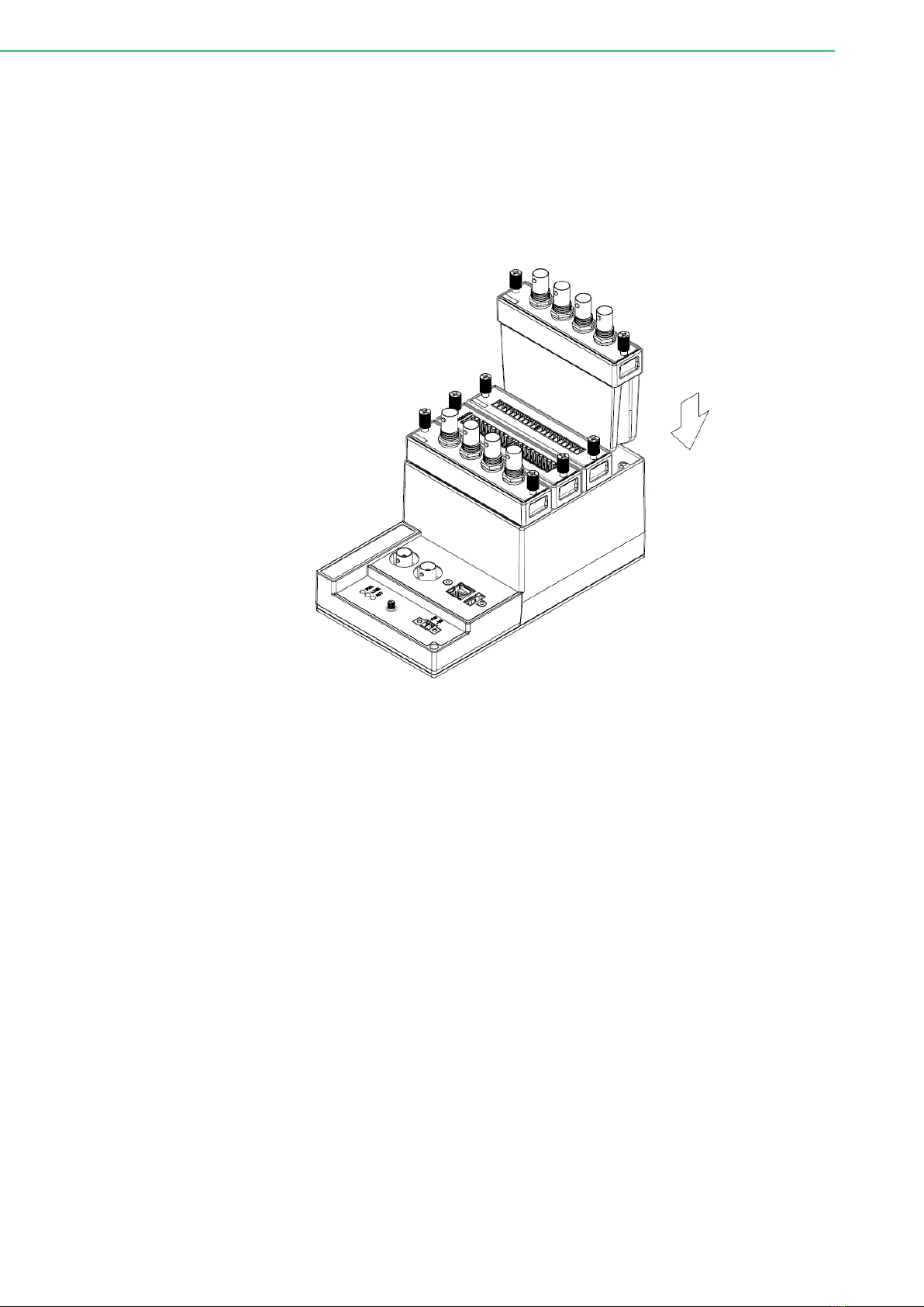
Below are the steps to insert the iDAQ modules into the iDAQ chassis.
1. Insert the module and follow the guide rail to the end.
2. Fix the two screws tight onto the chassis.
Figure 2.1 Installing iDAQ modules into the iDAQ chassis

9 iDAQ-731_751_763D User Manual
Chapter 2 Installation and Field Application
2.2 Signal Connection and Pin Assignment
2.2.1 Isolated Digital Input Connection
A digital input channel senses the state of the external sensor or switch, and passes
it through a galvanic isolator to the internal circuit. Figure 2.2 shows the digital input
signal connection.
Figure 2.2 Digital input signal connection.
There are several digital input common (DICOM) pins which are shorted together
inside the device. All digital input signals are referenced to DICOM. Therefore, the
negative terminal of the external voltage sources should be connected to DICOM for
proper operation.
If the input voltage is within OFF or ON state logic level, a logic low (0) or high (1) will
be sensed, respectively. If the input voltage is between the OFF and ON state logic
levels, the result is undetermined, which may be low or high. User should ensure the
ON/OFF state voltages of the sensors or switches meet the required values. Do not
input a voltage higher than the maximum value of ON state logic level or lower than
the minimum value of OFF state logic level. The device may be damaged under such
circumstance. Refer to A1. Isolated Digital Input (iDAQ-731) for OFF and ON state
logic level for the device.
Each digital input channel is equipped with a galvanic isolator, which can withstand a
large continuous voltage between external side and internal side. This prevents inter-
nal circuit from damaging when such fault condition happens.
iDAQ-731_751_763D User Manual 10
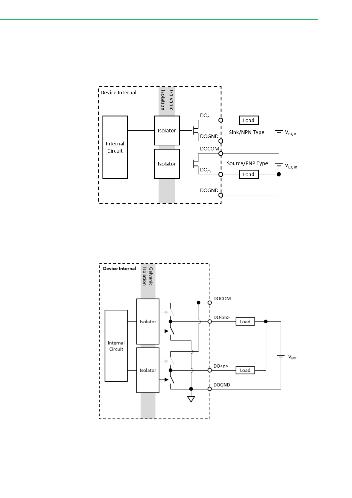
2.2.2 Isolated Digital Output Connection
A digital output channel sends a signal through a galvanic isolator to control the ON/
OFF state of a MOSFET switch. The state of the MOSFET switch then decides if the
load is conducting or not. The universal digital output channel supports both sink
(NPN) type and source (PNP) type connection as shown in Figure 2.3.
Figure 2.3 Digital output signal connection.
For a sink type digital output, the current which flows through the load is sunk by the
digital output (DO) terminal, and returns to the external source through the digital out-
put ground (DOGND) terminal. This is shown in Figure 2.4.
Figure 2.4 Sink (NPN) type digital output signal connection.
This manual suits for next models
2
Table of contents
Other Advantech Industrial Equipment manuals


Popular Industrial Equipment manuals by other brands


nystrom
nystrom CRAE4-BS Installation, operation and maintenance manual

Vega
Vega PLICSMOBILE Series operating instructions

Bastian Solutions
Bastian Solutions Shoe Sorter Installation and maintenance instructions

goodnature
goodnature AA-375R owner's manual

NetterVibration
NetterVibration NWE Series operating instructions

Utilicor
Utilicor MTC-100 Operator's manual


