Kwik Lok 086B-100 User manual

086B 02 18
TYPE SERIAL NO.
MODEL
EXECUTIVE OFFICE P.O. BOX 9548 YAKIMA, WA. 98909
TELEPHONE: 1-800-688-5945 or (509) 248-4770
FAX: (509) 457-6531
Internet: www.kwiklok.com
CORPORATION
®
®
TYPE 086B
SEMIAUTOMATIC
BAG CLOSER
INSTRUCTION
MANUAL

TYPE 086B CLOSER
TABLE OF CONTENTS
I SPECIFICATIONS.............................................1.1 - 1.4
II OPERATION......................................................2.1 - 2.7
III ADJUSTMENTS................................................3.1 - 3.16
IV TROUBLESHOOTING.......................................4.1 - 4.5
V PARTS IDENTIFICATION..................................5.1 - 5.25
VI WIRING..............................................................6.1 - 6.2
APPENDIX
BAG LENGTH FORMULA......................................A
BAGNECK TRIMMER OPERATION/PARTS..........B - E
SUGGESTED SPARE PARTS................................F
WARRANTY............................................................G
RETURNED MATERIALS AUTHORIZATION.........H
SECTION HEADING PAGE
GENERAL SAFETY INFORMATION
Be sure the following safety instructions are read, understood and become a part of daily practice when
operating or maintaining the closer.
1. Do not attempt to operate the closer until you understand its function. Study the manual carefully.
2. Keep all foreign material away from the drive system.
3. Keep fingers out of the closer and printer and away from any moving parts.
4. The printer cover must be in the closed position before applying power to and operating the closer / printer.
Electrical power should be disconnected from the closer while the printer cover is open.
5. Disconnect the power cord before making any adjustments or maintenance. Moving the switch to the “STOP”
position does not remove power from many electrical components, nor does it disable the motor.
All adjustments, except as noted, are to be made with power disconnected.
6. The closer is normally operated from a counter or table. While the closer is very stable when operated from a
flat a solid surface, care should be taken not use it in a way that could cause it to tip or fall from the operating
surface.
Kwik Lok 086B Models 100, 200, 200P, 600, 600P Closers are and certified.
The 086B Model 700P is not certified.
For technical support during regular business hours, call your local Kwik Lok distributor. For 24/7 technical support call
Kwik Lok Corporation at 1 800-688-5945 if you are in the continental U.S. For those outside the U.S., please dial + 1-
509-248-4770.
086B 02 18
®2018 KWIK LOK CORPORATION - ALL RIGHTS RESERVED
Kwik Lok® and Striplok® are Trademarks of Kwik Lok Corporation
The shape of the closure is protected by trademark registrations in many countries around the world.

SECTION I
Specifications
P 1.1
A. The 086B machine has various model options avail-
able. Models with the suffix “P” include printers.
Model 100 utilizes Series RJ (medium duty) clo-
sures.
Model 200 utilizes Series R (medium duty) and se-
ries S (heavy duty) closures with no adjustments re-
quired.
Model 200P utilizes Series RL, SL, RLP, and SLP
closures. With the addition of the optional label con-
version kits, Models 200 and 200P have the ability to
use closure - labels.
Models 600 and 600P are designed for use with an
ARC binding machine.
Model 700P is a closure - printer separator.
Refer to the Specification Chart for details on all
models.
B. The system will close a wide range of product size
variations. The Striplok closures are available in
many closure opening sizes to accommodate a large
number of variations in bag width and film material
thickness.
Upon request and upon receipt of sample bags,
the factory will gladly recommend the proper closure
opening sizes. Use the bag length formula
found in the appendix of this manual to help
determine the proper bag length needed.
C. A suggested spare parts inventory is listed in the
appendix. To save valuable time, it is recommend-
ed that an adequate supply of these parts be kept
on hand for needed repairs.
THE TYPE 086B
MACHINE SEMIAUTOMATICALLY
CLOSES PLASTIC BAGS
WITH THE STRIPLOK®CLOSURE
OR CLOSURE - LABEL.
086B 02 18

SECTION I
Specifications
P 1.2
PREFIX PRINTER TYPE
086B 100 No Printer Series RJ Medium Duty 30
086B 200 No Printer Series R & S Medium & Heavy
Dut
y
30
086B 600 No Printer Series L & U Medium & Heavy
Dut
y
30
086B 200P B, C, D, E Series RL & SL
RLP & SLP
Medium & Heavy
Duty 30
086B 600P B, C, D, E Series L & U Medium & Heavy
Duty 30
086B 700P B, C, D, E Series RL & SL
RLP & SLP
Medium & Heavy
Duty 54
TYPE
MODEL PLASTIC
THICKNESS
SPEED
(Bags/Min)
CLOSURE
*CONVERSION KITS
With the addition of the optional label conversion kits,
Models 200 and 200P have the ability to use closure - la-
bels. Three conversion kits are available:
Z0086071 KIT - L LABEL CONVERSION - MODEL 200
AND 200P ONLY
Z0086072 KIT - U LABEL CONVERSION - MODEL 200
AND 200P ONLY
Z0086073 KIT - CR LABEL CONVERSION - MODEL
200 AND 200P ONLY
**Model 600 and 600P are equipped with the necessary
parts needed to use both the Series “L” and “U” closure -
labels.
***Model 700P runs continuously, printing and dispens-
ing separated closures for hand applying to bagged
products.
PRINTER TYPE
B: Band Printer - non European
C: Band Printer - Europe
D: Type Block Printer - non European
E: Type Block Printer - Europe
*
*
**
**
***
1. The 086B Model P prints on closures or closure -
labels as defined in the chart above.
The printer uses a type band printhead or a block
with grooved rubber type. Contact your distributor or
Kwik Lok Corporation for printing supplies.
2. The standard closer is supplied with a table top
stand including feet, suction cups or a combination
of the two. An optional floor stand is available as well
as mounting brackets for an Oliver Slicer.
ADDITIONAL OPTIONS:
Bag Trimmer kits
Oliver Slicer mounts
Mount post
Floor Stand
3. The 086B is available for use with the following
electrical power:
115VAC, 60 Hz, 1 amp, single phase
220 - 250VAC, 50/60 Hz, 0.38 amp, single phase
086B 02 18
086B SEMIAUTOMATIC BAG CLOSING
MACHINE SPECIFICATIONS

SECTION I
Specifications
P 1.3
The following is a list of available printer
part numbers, closer models used on and their description.
PRINTER PART NUMBER MODEL PRINTER TYPE (DESCRIPTION)
P18-00098 PB Date band (USA and countries other than
Japan, European countries and Canada)
P18-00099 PB Numerical band (USA and countries other
than Japan, European countries and Canada)
P18-00100 PB Date band (Canada)
P18-00101 PB Date band (Mexico [Spanish])
P18-00102 PB Date Band (Europe and Russia)
P18-00120 PB Numerical band (Canada)
Contact®band PC Contact band (available in Europe only)
00-001138 PD Block - 2 line
00-001138 PE Block - 2 line (utilizes a contact ink roll
available in Europe only)
086B 02 18

SECTION I
Specifications
P 1.4
TYPE 086BP PRINT AREAS
CLOSURE AND CLOSURE - LABELS ARE SHOWN AT FULL SCALE
086B 02 18

SECTION II
Operation
P 2.1
A. OPERATING SEQUENCE:
(Figure 2.1)
The closer is ready to run when the closure is in
closing position, with both the power switch and the
run switch in the ”ON” position, and the ”READY”
light is on. When the closed bag and closure are re-
moved from the closure track, the machine com-
pletes the closing cycle placing the next closure in
the closing position. The machine is again ready for
the next bag. During the completion of the closing
cycle the ”READY” light will go off momentarily.
If no closure is available to move into the closing
position, the machine will continue to cycle and the
”READY” light will flash repeatedly until the run
switch is turned to the ”STOP” position.
The 086B Model 700P operating sequence is differ-
ent from the other 086B Models in that it prints,
feeds, and breaks off the closure continuously while
the run switch is in the “RUN” position. The closer
will stop cycling when the run switch is in the “STOP”
position or the last closure is manually removed from
the track assembly. When a new strip of closures is
inserted into the track and the “RUN” switch is in the
run position, a press of the green button, located on
the side access cover, will begin the continous cycle
of the machine.
THE PRINTER COVER MUST ALWAYS BE IN THE
CLOSED POSITION WHEN OPERATING THE
CLOSER.
The power switch and light must be off to cut
off power to the two sensor switches. Utilizing
the power switch instead of the run switch may
result in the machine not stopping in the neutral
position as required for loading the closure
strip. Use the power switch when clearing the
machine of debris or preforming minor service
work.
1. Plug in the closer.
2. Press the power switch to ”ON”.
3. Slide the closure strip into the closure track until
the strip stops (refer to Part B, LOADING A
ROLL OF CLOSURES in this section).
4. Press the run switch to ”RUN”. A closure will
move into the closing position, if one is not
already there, and the ”READY” light goes on
indicating the closer is ready for use.
5. Close the bag and remove it from the closer
(refer to Part E, CLOSING BAGS in this
section).
6. The closer cycles, prints a closure (If a printer
Model) and positions a new closure into the
closing position, ready for the next bag. The
”READY” light will go off momentarily as the clo-
sure is loading.
7. If no closure is available to move into the
closing position, the machine will continously
cycle and the ”READY” light will flash on and off
repeatedly until the run switch is pressed to
”STOP”. Closures can now be loaded into the
machine.
Figure 2.1
Power switch
Ready light
Run switch
086B 02 18

SECTION II
Operation
P 2.2
B. LOADING A ROLL OF CLOSURES:
1. Cycle the closer until the closures stop
advancing. Avoid cycling the closer more than
necessary when there is no closure in the
closing position. This will avoid a buildup of ink
residue on the closure track.
2. Move the run switch to “STOP” so the
mechanism is properly positioned.
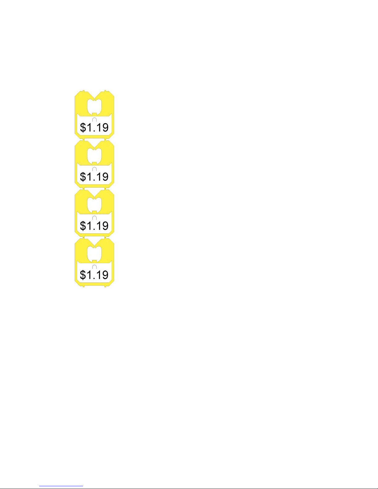
3. When closing with closures, insert the closure
hub into a new roll of closures. Be certain the
closures feed forward from the bottom of the
roll.
When closing with labels, insert the closure hub
so that the label of the closure is right side up
when the closure strip is in the closure track.
4. Install the hub and roll.
5. Open the printer cover and check to see if there
is any ink residue on the bottom of the closure
track within the printing area. Use a soft cloth
or tissue to wipe any ink off the closure track
so the ink will not smear on the underside of
the closure.
6. Remove the masking tape and feed the end of
the strip into the closure track until the first
closure has passed the check and is against
the stop. Close the printer cover.
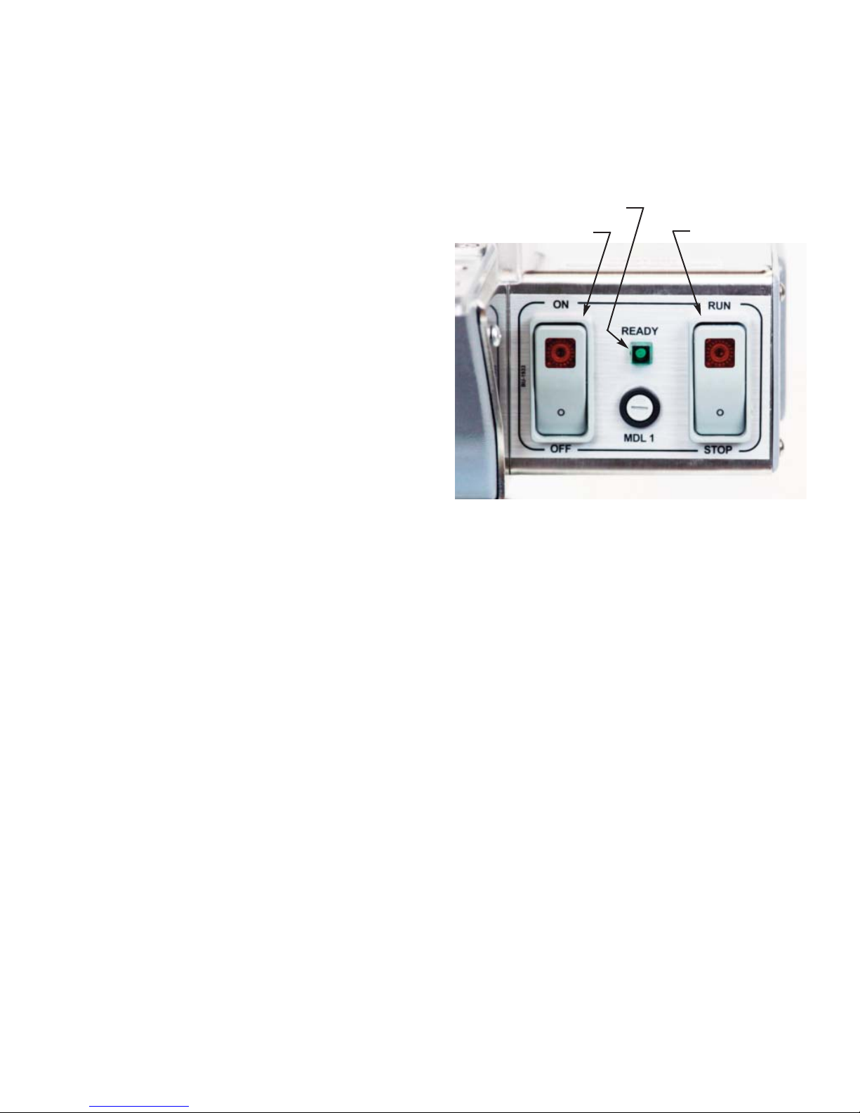
7. With the Power switch in the ”ON” position,
press the run switch to “RUN”. The closer will
cycle once and move a closure into the closing
position. Remove the first three unprinted
closures by hand. The closer is now ready to
close bags.
C. PREPARING THE PRINTER:
Figure 2.2 & 2.3
(If the machine is a non printer Model, skip to
Part E, CLOSING BAGS)
1. Open the printer cover.
2. Select the print image.
a. For the band printer, rotate the top of the print-
head toward the front of the closer so the
selected type characters can be easily viewed
through the window on the top of the print head.
Slide the selector knob out to select the desired
band and rotate the knob to select the desired
character. When finished, rotate the bandhead
back against the spacer.
b. For the typeholder block, remove the knurled
knob and slide the printer block off the shaft and
spring pin. Place the selected type in the
grooves that are the farthest away from the
holes in the mounting block. For normal viewing
on the closure the bottom edge of the characters
should be toward the middle of the block. Cen-
ter the type from side to side. Replace the block
on the shaft and pin so the type is close to the
ink roll arm. If the type or typeholder block is not
installed correctly, the type will not be inked
properly.
3. Unscrew the knob (Ink roll) and position the ink
roll between the knob and the cam follower.
4. Mate the ink roll to the end of the cam follower
and screw in the knob to secure it. Under most
conditions the ink roll can be left on the printer
until the ink is used up. The ink roll will not dry
out.
5. Close the printer cover.
6. Cycle the printer and discard the unprinted
closures.
086B 02 18

SECTION II
Operation
P 2.3
D. ADJUSTING THE PRINT FORCE:
Figure 2.2 & 2.3
DO NOT USE EXCESSIVE PRINT FORCE TO
COMPENSATE FOR PRINTING IMPERFECTIONS.
The operator can adjust the print force.
Always operate the printer with the minimum print
force that will produce acceptable printing. A quarter
turn of the knob is a large adjustment. If a
significant change in print quality is not noticed,
return to the previous setting and refer to Section III,
Adjustments and Section IV, Trouble Shooting to
correct any problems.
When the ink roll will no longer adequately ink the
type, replace it. Do not attempt to extend the life of
the ink roll by increasing the printing force.
To increase the print force, turn the knob counter-
clockwise. If the effort to turn the knob suddenly de-
creases, the maximum print force has been reached.
To decrease the print force, turn the knob clock-
wise.
E. CLOSING BAGS:
Figure 2.4
1. Grasp the bag as shown. Spin the bag to twist
the bag neck. Twisting the bag helps the
material to enter the closure smoothly.
2. The lower hand should form a “V” to trap all of
the bag material. This helps to completely
insert the bag material into the closure opening.
3. Do not jam the bag material straight into the
closure opening. The top hand should lead the
bottom hand. Follow up with the lower hand
until all of the bag neck is in the closure. A tight
package is accomplished by holding the
contents of the bag snugly up against the
underside of the closure track.
4. Remove the closed bag with a horizontal
motion.
086B 02 18
Figure 2.2
View window
Rotate printhead
Knob
(print force)
Selector
knob
Spacer
Typeholder block
Knurled knob
Figure 2.3
Knob
(Ink roll)

SECTION II
Operation
P 2.4
F. SETUP:
Figure 2.5 - 2.7
Refer to the Specifications section for additional de-
tails on model setup.
The Model 100 is set up to run Series RJ closures.
The standard configuration for Models 200 and 200P
is to utilize closures with optional conversion kits.
They are also capable of using L closure - labels, U
closure - labels, or CR closure - labels. The conver-
sions are simple to execute and can easily be done
by the user. The closer can be converted back to
the standard configuration.
The only tool needed for the conversion is a 3mm
hex wrench, which is included with the closer. A tool
holder on the back of the closer frame next to the
power cord connection provides a convenient place
to keep the wrench. The closer comes with two re-
movable shims. One or two of the shims may need
to be removed for a specific configuration. There
are two studs located inside the closer stand to hang
the shims when not in use.
Top plate
mounting hole
(4 places)
Top plate
Frame spacer
Roll supports
Support mounting
holes
Closure hub
Figure 2.5
Figure 2.6
Bracket
(Printer mounting)
Model
100 only
Model
100 only
Roll support
bracket
086B 02 18
Figure 2.4

SECTION II
Operation
P 2.5
G. CONVERSION PROCEDURE:
Figure 2.5 - 2.8
Remove the closure or closure - label strip and hub
from the closer. The closer can be easily cleared of
closures or closure - labels by pressing the Lok pick
and stop down. The closer can be more easily
cleared of the closure strip by breaking the strip and
then running the closer until the closure track is
empty.
DISCONNECT THE CLOSER FROM POWER.
The roll supports can be positioned in three different
locations (Widths) to accommodate the three hubs
available. Threaded holes are located in the closer
top plate (Closer with no printer) or on the roll sup-
port bracket (Closer with printer). The support
mounting holes to be used depends on which Clo-
sure / Closure - label is to be used.
CLOSURE TO SERIES L CLOSURE - LABEL
CONVERSION:
1. The roll supports are not relocated.
2. From the front of the closer, identify and remove
the right M5 button head screw securing the
right lok guide shim to the track (Figure 2.8 Shim
Position Series L Closure - Label). There are
two threaded holes in the closer stand to keep
unused M5 screws.
3. Remove the right shim and hang it on the studs
located inside of the closer stand.
4. Insert the L label hub into a roll of L closure - la-
bels and place them in the closer.
5. Insert the closure - label strip, label side up, into
the closure track. Feed the strip into the track
until the strip engages the closure stop.
U closure - label
roll support position
RJ closure
roll support position
Figure 2.7
GREEN indicates mounting position of roll supports.
The hole patterns shown apply to 086B (without printer) and 086BP (printer) closers. The roll support bracket
(for the optional printer Figure 2.6) has the same pattern of holes to correctly position the roll supports.
CR closure - label
roll support position
R, S, RL and SL closures
and L closure - label
roll support position
086B 02 18

SECTION II
Operation
P 2.6
CLOSURE TO SERIES CR CLOSURE - LABEL
CONVERSION:
1. Remove the two M5 screws securing the two lok
guide shims. There are two threaded holes in
the closer stand to keep unused M5 screws.
2. Remove both shims (Figure 2.8 Shim Position
Series CR and U Closure - Label) and hang
them on the studs located inside of the closer
stand.
3. Remove the two frame spacer mounting screws
and remove the spacer from between the two
roll supports.
4. Remove the four screws securing the two roll
supports to the closer.
5. Fasten the CR closure - label spacer between
the two roll supports with the two M5 screws that
were used for the previous spacer.
6. Align the mounting holes of the roll supports to
the appropriate threaded holes on the closer
(Figure 2.7).
7. Fasten the two roll supports to the closer using
the four M5 screws that were removed earlier.
8. Insert the CR closure - label hub into a roll of CR
series closure - labels and place them in label
side up.
9. Insert the end of the closure - label strip, label
side up, into the closure track. Feed the strip
into the track until the strip engages the closure
stop.
086B 02 18
Shim position (1 Shim)
Series L Closure - Label
Shim position (No shims)
Series CR and U Closure - Label
Shim position (2 Shims)
Series R, S, RL, and SL shim position
00-001564 Shim -
right lok guide
00-001584 Shim -
left lok guide
Shim mounting
screws
Figure 2.8
Lok track shim position

SECTION II
Operation
P 2.7
086B 02 18
CLOSURE TO SERIES U CLOSURE - LABELS
CONVERSION:
1. Remove the two M5 screws securing the two
shims (Figure 2.8 Shim position Series CR and
U Closure - Label). There are two threaded
holes in the closer stand to keep unused M5
screws.
2. Remove both shims and hang them on the studs
located inside of the closer stand.
3. Remove the two frame spacer mounting screws
and remove the spacer from between the two
roll supports.
4. Remove the four screws securing the two roll
supports to the closer.
5. Fasten the U closure - label spacer between the
two roll supports with the two M5 screws that
were used for the previous spacer.
6. Align the mounting holes of the roll supports to
the appropriate threaded holes on the closer
(Figure 2.7).
7. Fasten the two roll supports to the closer using
the four M5 screws that were removed earlier.
8. Insert the U closure - label hub into a roll of U
series closure - labels and place them in the
closer.
9. Insert the end of the closure - label strip, label
side up, into the closure track. Feed the strip
into the track until the strip engages the closure
stop.

This page intentionally blank.

SECTION III
Adjustments
P 3.1
THE FOLLOWING ADJUSTMENTS ARE TO BE
PERFORMED WITH THE CLOSER ELECTRICAL
POWER DISCONNECTED.
A. CLOSURE TRACK ASSEMBLY REMOVAL:
Figures 3.1 - 3.3
Some of the adjustments described in this section
require removal of the closure track assembly.
1. Remove the access cover.
2. Disconnect the two gold colored closure stop
springs from the spring anchor screw. When the
springs are reattached be careful not to stretch
them.
3. Disconnect the ink roll arm spring (Printer Model
only).
4. Remove the flat head mounting screws which at-
tach the closure track assembly to the closer
main frame. Note the closure track assembly
can be removed from the closer without remov-
ing the ink roll assembly or the printer cover
from the closure track (Printer Model only).
When remounting the track assembly, tighten
the mounting screws evenly.
5. Lift the closure track assembly slightly and
depress the tip of the pick to disengage it from
the closure track.
6. Lift the closure track assembly slightly off the
frame and disconnect the two wire leads from
the sensor lever limit switch.
To remount the closure track assembly, reverse the
above procedure. Before closing the access cover,
check to see that there are no pinched wires or
wires routed close to moving parts.
Figure 3.2
Figure 3.1
Roll support
Closure
stop
Closure stop
springs (2)
Closure stop
mount
Closure stop
drive pins (2)
086B 02 18
Spring anchor screw
Electrical
enclosure
Closer frame
Roll
support
bracket
Closure
track
assembly
Access cover
Closure track
mounting
screws (6)
Printer assembly

SECTION III
Adjustments
P 3.2
B. TOP CLOSURE TRACK REMOVAL:
Figure 3.1
The top of the closure track can be removed
from the closer while the closure track assembly
remains attached to the closer mainframe. This can
be done to expose the slot that the closures move
through. The closure track can be inspected and
cleaned if needed.
1. Disconnect the 0S-006 spring from the ink roll
arm of the printer assembly (Printer Model only).
2. Remove the flat head screws from the track.
Note the different screw lengths upon
removal.
3. Remove the top track from the remaining lok
track assembly.
C. REMOVE THE FRONT SHIELD:
Some of the adjustments described in this section
require removal of the front shield.
DISCONNECT POWER
1. Remove the side access cover from the closer
frame.
2. Remove the two self tapping phillips screws
used to fasten the sides of the shield to the
closer frame
3. Loosen (turn clockwise) the two shield mounting
screws on the underside of the closer frame.
4. Press lightly from the inside of the closer frame
on the backside of the shield to remove it.
086B 02 18
086B Stop mount
position (Models 200,
600, 700)
Stop mount screws (2)
Closure stop
tip centered
086B Stop mount
position (Model 100)
Figure 3.3
CHECK AND CLOSURE
STOP (Model 100)
CHECK AND CLOSURE STOP
(Models 200, 600, 700)
Check
Stop mount
Check
Check mounting
position (Models 200,
600, 700)
Check mounting
position (Model 100)
Check mounting
position (Model 100)
Check mounting
position (Models 200,
600, 700)

SECTION III
Adjustments
P 3.3
D. CHECK POSITION:
Figure 3.3
The check stops the closure strip from moving
backward while the pick retracts.
Refer to Figure 3.3 to further understand the check
mounting position. For this adjustment the closure
track must be removed from the closer.
For models 200, 600, and 700 the check is mounted
in the back mounting holes (farthest from the front of
the closure track). For Model 100, the check is
mounted in the front mounting holes.
1. With the check mounted in the correct holes,
and the mounting screws loose, slide the check
forward toward the front of the closure track to
the end of the mounting slots and tighten the
mounting screws.
E. CLOSURE STOP POSITION:
Figure 3.3 and 3.4
The end closure is separated from the closure strip
while the closure stop limits the travel of the second
closure in the strip as the pick continues to advance
the first closure. As with the position of the check,
the stop mount is located in a specific way
depending on the closer model being adjusted.
1. The stop mount is mounted as shown.
2. Be sure the beveled edges of the mount are
facing the closure stop.
The closure stop tip must be centered in the slot
located in the bottom track for it.
3. Slightly loosen the stop mount mounting screws.
4. Move the closure stop tip side to side until it is
centered in the slot.
5. Tighten the mounting screws.
6. Turn the closure track assembly over so it is
right side up. Again check the position of the
closure stop tip as this is the way the track as-
sembly is oriented during operation. Readjust if
needed.
086B 02 18
Closure stop
setscrew
Beveled edges of
the stop mount
Closure stop
Figure 3.4
(Stop mount is positioned for Models 200, 600, 700) Figure 3.5

SECTION III
Adjustments
P 3.4
F. CLOSURE STOP SET SCREW ADJUSTMENT:
Figure 3.5 and 3.6
When properly adjusted, the closure stop set screw
sets the height of the closure stop. As the closure
strip advances, the second closure in the strip is
stopped. The leading closure continues to move
forward and is then separated from the closure strip.
1. Remove any closures from the track assembly.
2. Locate the top of the set screw.
3. Turn the sets crew in or out to lower or raise the
tip of the closure stop until it is 1/8” (3mm) below
the top of the top track. If the tip of the
stop will not raise as the set screw is turned out,
the stop may be bowed. If so, the stop must be
removed from the machine and the part
straightened. It is recommended that remove-
able threadlocker be used on the set screw.
G. LOK SENSOR SPRING:
Figure 3.7
The lok sensor spring is designed to apply force
to the lok sensor tip keeping it against the side of
the closure, as well as upward against the underside
of the closure track. For the spring to operate
correctly, it must be mounted as shown in Figure
3.7.
H. SENSOR LEVER STOP ADJUSTMENT:
Figure 3.7 - 3.9
The lok sensor stop is a bushing which limits the
travel of the sensor lever when no closures are
present. The bushing is secured under an M5
socket head screw. The bushing (sensor lever
stop) can be adjusted to set the lok sensor stop
position. When no closures are present, the lok
sensor tip should be centered below the inspection
hole in the top track (Figure 3.8).
1. Loosen the mounting screw and move the
bushing as needed.
2. Retighten the mounting screw.
086B 02 18
Lok sensor spring anchor
Lok sensor
Top track
Figure 3.7
Sensor lever spring (0S-012)
Bushing (lok sensor stop)
1/8” (3mm)
Top track
Closure stop
Bottom track
Closure stop set screw
Figure 3.6

SECTION III
Adjustments
P 3.5
I. LOK SENSOR SWITCH ADJUSTMENT:
Figure 3.9
The sensor switch detects whether or not there is a
closure in closing position. When a closure moves
into the closing position, the sensor switch stops the
motor at the end of the cycle. When the closure is
removed, the switch starts the motor.
1. Check to see if the sensor lever stop is adjusted
correctly, refer to Part H, this section.
2. Turn the closure track upside down.
3. Feed a short strip of closures (4 or 5) through
the track until the leading edge of the first
closure just slides past the lok sensor then
back out until the closure is free of the lok sen-
sor. Continue to slide the strip back and forth
while listening for an audible “click” indicating
that the lok sensor switch is turning on and off.
If the strip of closures moves forward so far that
it can’t back up, push it out of the front of the
track and start over. Adjust if needed as follows.
4. Slightly loosen the two mounting screws in the
sensor block (Figure 3.9).
086B 02 18
Locate tip of the pick here
(Models 200, 600, 700)
Lok sensor
tip (All models)
Lok sensor
tip (All models)
Figure 3.8
Micro switch
(Lok sensor)
Switch adjustment
screws (2) Sensor
block
Check
Lok sensor
Bushing (Lok
sensor stop)
Figure 3.9
Locate tip of the pick
here (Model 100)

SECTION III
Adjustments
P 3.6
5. Move the switch and sensor block toward or
away from the lok sensor. Listen for an
audible ”click” of the switch as it turns on and
off.
6. Tighten the mounting screws when the switch
actuates as described above.
086B 02 18
Top plate
Closure track
Closure track
mounting screws (4)
Cam switch
Closer cam
Pick assembly
Motor mounting
screws (3)
Motor mounting
plate
Access cover
Motor
Top plate mounting
screws (4)
Pick spring
Electrical enclosure
cover
Electrical enclosure
Motor fan
Figure 3.10
This manual suits for next models
5
Table of contents
Other Kwik Lok Industrial Equipment manuals
Popular Industrial Equipment manuals by other brands

Siemens
Siemens Sivacon S8 operating instructions

handtmann
handtmann 09513 operating manual

BONFIGLIOLI
BONFIGLIOLI 700C Series Installation and service manual

Endress+Hauser
Endress+Hauser Cleanfit P CPA471 operating instructions

Jäger
Jäger Z80-K440.21 S5A ER16 vs/IP manual

Sacmi
Sacmi Imola CHS Series instruction manual