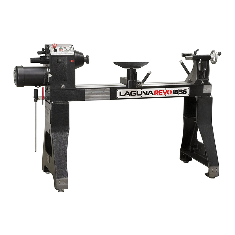
IGM LAGUNA Revo 1836 User manual

Producent
Laguna Tools Inc
2072 Alton Pkwy
Irvine, CA 92606,
USA
Phone: +1 800-234-1976
Website: www.lagunatools.com
Distributor
IGM nástroje a stroje s.r.o.
Ke Kopanině 560, 252 67, Tuchoměřice
Czech Republic, EU
Tel: +420 220 950 910
www.igmtools.com
2021-12-17
151-1836 LAGUNA Woodturning Lathe Manual EN v1.9 A4ob
Woodturning lathe
(Operating Instructions EN)
REVO 1836
www.igmtools.info
PDF ONLINE

-2-www.igmtools.com

-3-www.igmtools.com
Contents
1. Declaration of conformity
1.1 Warranty
2. About this manual
3. Specications
3.1 Parts of the machine
3.2 Technical data
3.3 Noise emission
4. General safety
4.1 Safety Rules
4.2 Electrical connections
5. Receiving your machine
5.1 Unpacking and transport
5.2 Receiving the lathe
5.3 Locating your machine
6. Assembly and setup
6.1 Assembling the legs to the bed of the lathe
6.2 Cleaning the machine
6.3 Fitting the rotating centre
6.4 Fitting the drive centre into the head stock
6.5 Fitting the face plate
6.6 Lathe controls
6.7 Variable speed adjustment knob
6.8 High / low speed
6.9 Indexing the spindle
7. Maintenance
8. Troubleshooting
1. Declaration of conformity
We declare that this product is in
compliance with the Directives and Standards
on page 2 of this manual.
1.1 Warranty
IGM Tools & Machinery strives to always
deliver high-quality machinery. The warranty is
governed by the valid terms and conditions of
IGM Tools & Machinery available at
www.igmtools.com.
2. About this manual
This manual is intended to thoroughly cover the
setup up, maintenance, and proper adjustments
of your new purchase. Aside from the
proceeding general safety considerations,
this manual DOES NOT cover woodworking
or metalworking techniques that are possible
with this product and the appropriate safety
precautions necessary for safe practices.
3. Specications
Wood turning lathes are typically used to shape
wood into cylindrical proles. Objects made on
a wood lathe include such items as furniture
legs, lamp posts, baseball bats, bowls and
other ornamental forms. Wood lathe tooling
consists of xtures and securing devices for the
work piece, a moveable tool rest, and hand-
held cutting tools.
3.1 Parts of the machine
The lathe consists of a number of major parts,
which are discussed in this manual. Take the
time to read this section and become familiar
with the machine.
Identication
There is a plate at the back of the machine
listing all the manufacturing data, including
the serial number, model, etc.
Lathe Bed
The bed is a heavy steel welded construction.
Pic. 1
Underside of lathe bed
Pic. 2
Lathe legs
The Legs are cast iron, and their heavy
construction gives the machine a low centre of
gravity and ensures that it is very stable. The
legs are supplied with adjustable feet to allow
the machine to be levelled.
Legs with adjustable feet assembled.
Pic. 3
Head stock
The head stock is cast iron and houses the
variable speed control and motor. The spindle
can be locked in 14 / 36 and 48 positions.
Headstock removed from the bed
Pic. 4
Headstock attached to bed
Pic. 5
Tail stock
The tail stock is of cast iron construction, and
the spindle has a travel of 4 1/2 in. It can
accommodate centres and other tools which
have a number 2 Morse Taper. The tail stock
can be moved to any position on the lathe bed
and locked to suit the job at hand.
Tail stock viewed from the back.
Pic. 6
EN - English
Operating instructions (Translation of original)
Dear Woodworker,
Thank you for your purchase and welcome to the Laguna Tools group of discerning woodworkers. We understand that you have a
choice of where to purchase your machines and appreciate the condence you have in the Laguna Tools brand.
Every machine manufactured by Laguna Tools has been carefully designed and well thought through from a woodworker’s perspective.
Through hands-on experience, Laguna Tools is constantly working hard to make innovative, precision products. Products that inspire
you to create works of art, are a joy to run and work on, and encourage your performance.

-4-www.igmtools.com
Tail stock viewed from the front
Pic. 7
Tool rest
The tool rest can be moved to any position on
the lathe bed and locked to suit the job at hand.
The tool rest has a tall prole to allow the bowl
turner to turn steep angles. The leading edge
is made from 6 mm hardened steel.
Tool rest assembled to the bed
Pic. 8
Tool rest
Pic. 9
Electrical system
220V: The electrical control system (VFD) is
housed at the back of the head stock, The VFD
converts single phase 220v to three phase.
There is a speed readout at the front of the
lathe with controls to ne adjust the rpm of
the spindle. A power cord with 220V plug is
provided.
Tail stock travel 115 mm
Tail stock removal Self-ejecting
Tail stock taper MK2
Faceplate 76 mm
Bed material Steel
Weight (net/ship) 194 kg / 206 kg
3.3 Noise emissions
Equivalent A-weighted Sound pressure level
according to EN ISO 3746: 75.66 dB(A).
Uncertainty, K in decibels: 4.0 dB (A) according
to EN ISO 4871 The gure quoted is emission
levels and are not necessarily safe working
levels. Whilst there is a correlation between the
emission and exposure levels, this cannot be
used reliably to determine whether or not further
precautions are required. Factors that inuence
the actual level of exposure of the workforce
include characteristics of the work room, the
other sources of noise, etc. i.e. the number of
machines and other adjacent processes. Also
the permissible exposure level can vary from
country to country, This information, however,
will enable the user of the machine to make a
better evaluation of the hazard and risk.
Pic. 13
4. General safety
“WARNING“: For Your Own Safety Read
Instruction Manual before Operating Lathe
4.1 Safety Rules
(a) Wear eye protection.
(b) Do not wear gloves, a necktie, or loose
clothing.
(c) Tighten all locks before operating.
(d) Rotate work piece by hand before applying
power.
(e) Rough out work piece before installing on
faceplate.
(f) Do not mount split work piece or one
containing a knot.
(g) Use lowest speed when starting new work
piece.
• Keep guards in place and in working order.
• Remove adjusting keys and wrenches. Form
habit of checking to see that keys and adjusting
wrenches are removed from tool before turning
it on.
• Keep work area clean. Cluttered areas and
benches invite accidents.
• Don‘t use in a dangerous environment. Don‘t
use power tools in damp or wet locations, or
expose them to rain. Keep work area well
lighted.
VFD with cover open
Pic. 10
Power cord
Pic. 11
Tool storage
A tool storage bracket which can be mounted
on either leg.
Tool storage bracket
Pic. 12
3.2 Technical data
Motor Induction, 1420 rpm, 1,5 kW, S1
Voltage 230V, 50 Hz, 1 Ph.
3 phase output
Recommended breaker size 16 A, tripping
characteristic C (16/1/C).
Swing over bed 457 mm
Swing over banjo 343 mm
Outboard swing max. 813 mm
Distance between centres 914 mm
Floor to spindle centre 1054 mm
Floor to bed height 826 mm
Dim. W x D x H 1524 x 660 x 1194 mm
Tool rest 305 mm
Speed range high: 135 – 3500 rpm
Speed range low: 50 – 1300 rpm
VFD Delta
Spindle M33 x 3.5 mm, righthanded
Spindle taper MK 2
Spindle lock Spring loaded
Spindle indexing 14 / 36 / 48 with lock
Head stock and tail stock bore 9,5 mm

-5-www.igmtools.com
• Keep children away. All visitors should be kept
at a safe distance from the work area.
• Make your workshop kid proof with padlocks,
master switches, or by removing starter keys.
• Don‘t force tool. It will do the job better and
safer at the rate for which it was designed.
• Use right tool. Don‘t force tool or attachment
to do a job for which it was not designed.
• Use proper extension cord. Make sure your
extension cord is in good condition. When using
an extension cord, be sure to use one heavy
enough to carry the current your product will
draw. An undersized cord will cause a drop
in line voltage resulting in loss of power and
overheating.
• Wear proper apparel do not wear loose
clothing, gloves, neckties, rings, bracelets, or
other jewellery which may get caught in moving
parts. Non-slip footwear is recommended. Wear
protective hair covering to contain long hair.
• Always use safety glasses. Also use a face
or dust mask if cutting operation is dusty.
Everyday eyeglasses only have impact resistant
lenses, they are not safety glasses.
• Secure work. Use clamps or a vice to hold the
work when practical. It‘s safer than using your
hand and it frees both hands to operate the tool.
• Don‘t overreach. Keep proper footing and
balance at all times.
• Maintain tools with care. Keep tools sharp
and clean for best and safest performance.
Follow instructions for lubricating and changing
accessories.
• Disconnect tools before servicing and when
changing accessories, such as blades, bits,
cutters, and the like.
• Reduce the risk of unintentional starting. Make
sure power switch is in the o position before
plugging the machine in.
• Use recommended accessories. Consult the
owner‘s manual for recommended accessories.
The use of improper accessories may cause
risk of injury to persons.
• Never stand on tool serious injury could
occur if the tool is tipped or if the cutting tool is
unintentionally contacted.
• Check damaged parts. Before further use of
the tool, a guard or other part that is damaged
should be carefully checked to determine that
it will operate properly and perform its intended
function - check for alignment of moving parts,
binding of moving parts, breakage of parts,
mounting, and any other conditions that may
aect its operation. A guard or other part that
is damaged should be properly repaired or
replaced.
• Direction of feed. Feed work into a blade or
cutter against the direction of rotation of the
blade or cutter only.
• Never leave tool running unattended. Turn
power o. Don‘t leave tool until it comes to a
complete stop.
Location of warning signs
Pic. 14
Locking the lathe
It is strongly recommended that the lathe is
never be left unattended in the unlocked
condition.
To lock the machine it is recommended that a
cover (not supplied) is made to lock the control
panel. We have supplied two concepts for
locking the panel (see below). The cover can
be made from wood or plastic.
First, push down the emergency stop. Then
lock the cover together by putting padlocks [not
included] on the two handles on the control
panel. To safeguard your machine from
unauthorized operation and accidental starting
by young children, the use of padlocks is
strongly recommended.
Pic. 15
Pic. 16
4.2 Electrical connections
Make sure that the power supply meets
the machine‘s requirements (230V). We
recommend using a 16 A breaker, tripping
characteristic C (16/1/C). Note.: Perform
adjustments with the help of a qualied
electrician.
VFD with cover open
Pic. 17
Wooden safety cover Padlocks
Padlocks
Emergency stop switch
Plastic safety cover
Other manuals for LAGUNA Revo 1836
1
This manual suits for next models
1
Table of contents
Other IGM Lathe manuals
