Ignite B6A800101 Manual

7513187enUS (A)
March 2023
Printed in USA
Original Instructions
© 2023 Ignite Attachments.
All Rights Reserved.
Operation & Maintenance Manual
Sweeper
Sweeper 72” S/N: B6A800101 & Above


1
FOREWORD............................................................................................................................................................3
MANUFACTURER.............................................................................................................................................3
North America ...............................................................................................................................................3
SERIAL NUMBER LOCATION ...........................................................................................................................3
Attachment Serial Number ...............................................................................................................................3
ATTACHMENT IDENTIFICATION .......................................................................................................................4
FEATURES AND ACCESSORIES ......................................................................................................................4
Standard Items..............................................................................................................................................4
Options And Accessories.................................................................................................................................4
SAFETY AND TRAINING RESOURCES....................................................................................................................5
SAFETY INSTRUCTIONS..................................................................................................................................5
Safe Operation Is The Operator’s Responsibility ................................................................................................... 5
Safe Operation Needs A Qualified Operator.........................................................................................................5
Use Safety Rules ...........................................................................................................................................5
Call Before You Dig ........................................................................................................................................5
Silica Dust Exposure.......................................................................................................................................6
FIRE PREVENTION...........................................................................................................................................6
Maintenance.................................................................................................................................................6
Operation.....................................................................................................................................................6
Electrical......................................................................................................................................................6
Hydraulic System...........................................................................................................................................6
Fueling ........................................................................................................................................................7
Starting........................................................................................................................................................7
Spark Arrester Exhaust System.........................................................................................................................7
Welding And Grinding .....................................................................................................................................7
Fire Extinguishers ..........................................................................................................................................7
PUBLICATIONS AND TRAINING RESOURCES .................................................................................................8
ATTACHMENT SIGNS (DECALS) ......................................................................................................................9
OPERATING INSTRUCTIONS ................................................................................................................................ 11
DAILY INSPECTION........................................................................................................................................ 11
Inspecting The Attachment Mounting Frame ...................................................................................................... 11
Inspecting The Machine Quick Coupler............................................................................................................. 11
GUTTER BRUSH OPERATION (IF EQUIPPED) ................................................................................................ 12
OPERATING PROCEDURE WITH LOADERS................................................................................................... 13
Approved Models And Requirements ............................................................................................................... 13
Machine / Attachment Setup........................................................................................................................... 13
Entering And Exiting The Machine ................................................................................................................... 14
Installing The Attachment .............................................................................................................................. 15
Hydraulic Quick Couplers .............................................................................................................................. 19
Control Functions......................................................................................................................................... 20
Operation With The Loader ............................................................................................................................ 20
Removing The Attachment............................................................................................................................. 24
LIFTING THE ATTACHMENT........................................................................................................................... 25
TRANSPORTING THE ATTACHMENT ON A TRAILER ..................................................................................... 26
Fastening The Attachment On A Trailer............................................................................................................. 26
TRANSPORTING THE ATTACHMENT AND MACHINE ON A TRAILER............................................................. 27
Transporting The Attachment And Machine On A Trailer ....................................................................................... 27
PREVENTIVE MAINTENANCE............................................................................................................................... 28
TABLE OF CONTENTS

2
MAINTENANCE SAFETY WARNINGS ............................................................................................................. 28
TROUBLESHOOTING ..................................................................................................................................... 29
Troubleshooting Chart................................................................................................................................... 29
REMOVING AND INSTALLING THE BRISTLES ............................................................................................... 30
REMOVING AND INSTALLING THE CHAIN ..................................................................................................... 33
REMOVING AND INSTALLING THE CUTTING EDGE....................................................................................... 35
LUBRICATION LOCATIONS............................................................................................................................ 36
ATTACHMENT STORAGE AND RETURN TO SERVICE ................................................................................... 36
Attachment Storage...................................................................................................................................... 36
Return To Service ........................................................................................................................................ 36
SWEEPER SPECIFICATIONS ................................................................................................................................ 37
WARRANTY .......................................................................................................................................................... 38
ATTACHMENT / IMPLEMENT WARRANTY...................................................................................................... 38
TABLE OF CONTENTS

3
MANUFACTURER
North America
Ignite Attachments
2741 20th Avenue South
Moorhead, MN 56560
SERIAL NUMBER LOCATION
Attachment Serial Number
Figure 1
C208295
Always use the serial number (Item 1) when requesting
service information or when ordering parts. Early or later
models (identification made by serial number) may use
different parts, or it may be necessary to use a different
procedure in doing a specific service operation [Figure 1].
FOREWORD

4
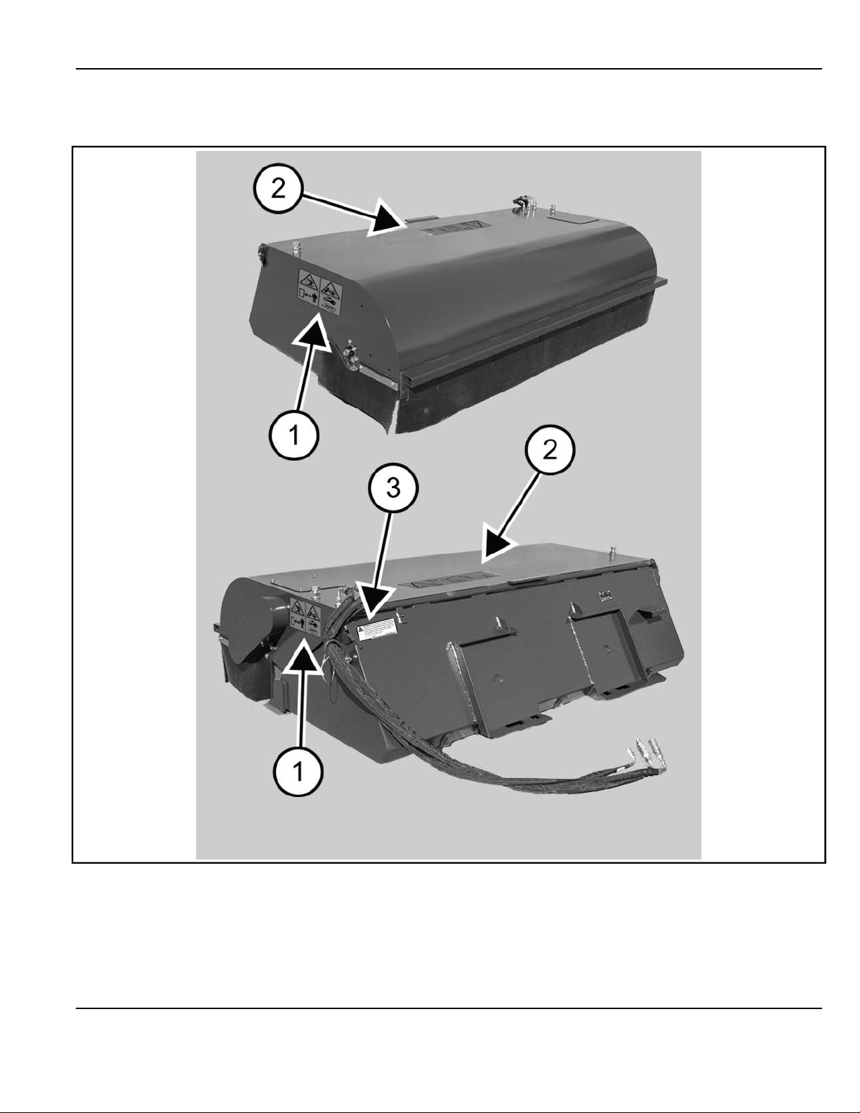
ATTACHMENT IDENTIFICATION
C209917a
Ref. Description
1 Skirt
2 Shaft Bearing
3 Bristle Depth Adjustment
C209917a
Ref. Description
1 Chain Drive Cover
2 Hydraulic Motor Access Panel
3 Mounting Frame
4 Hydraulic Quick Couplers
FEATURES AND ACCESSORIES
Standard Items
The attachment is equipped with the following standard
items:
• Polypropylene Bristles
• Reversible Cutting Edge
Options And Accessories
Below is a list of Options and Accessories available for
your attachment. See your Ignite Attachments dealer for
other available options and accessories.
• Gutter Brush (Right side only)
FOREWORD

5
SAFETY INSTRUCTIONS
Safe Operation Is The Operator’s
Responsibility
Safety Alert Symbol
This symbol with a warning statement means:
“Warning, be alert! Your safety is involved!” Carefully
read the message that follows.
DANGER
The signal word DANGER on machine signs and in
the manuals indicates a hazardous situation which, if
not avoided, will result in serious injury or death.◂
D-1002
WARNING
The signal word WARNING on the machine and in the
manuals indicates a potentially hazardous situation
which, if not avoided, could result in serious injury or
death.◂
W-2044
IMPORTANT
This notice identifies procedures which must be
followed to avoid damage to the machine.◂
I-2019
The machine and attachment must be in good operating
condition before use.
Safe Operation Needs A Qualified Operator
For an operator to be qualified, he or she must not use
drugs or alcoholic drinks which impair alertness or
coordination while working. An operator who is taking
prescription drugs must get medical advice to determine
if he or she can safely operate a machine.
Use Safety Rules
• Read and follow instructions in the machine and the
attachment’s Operation & Maintenance Manual
before operating.
• Check for underground lines before operating
attachment (if applicable).
• In addition to the design and configuration of
equipment, hazard control, and accident prevention
are dependent upon the awareness, concern,
prudence, and proper training of personnel involved
in the operation, transport, maintenance, and
storage of equipment.
• Check that the attachment is securely fastened to
the machine.
• Make sure all the machine controls are in the neutral
position before starting the machine.
• Operate the attachment only from the operator’s
position.
• Operate the attachment according to the Operation
& Maintenance Manual.
• When learning to operate the attachment, do it at a
slow rate in an area clear of bystanders.
• DO NOT permit personnel to be in the work area
when operating the machine and attachment.
• The attachment must be used ONLY on approved
machines. Visit igniteattachments.com for an
updated list of approved attachments for each
machine model.
• DO NOT modify equipment or add attachments that
are not approved by the manufacturer.
• DO NOT make any adjustments or repairs on the
machine or attachment while the engine is running.
• Keep shields and guards in place. Replace if
damaged.
Call Before You Dig
P200081
Dial 811 (USA Only)
Dial 1-888-258-0808 (USA & Canada)
When you call, you will be directed to a location in your
state / province / city for information about buried lines
(telephone, cable TV, water, sewer, gas, etc.).
SAFETY AND TRAINING RESOURCES

6
Silica Dust Exposure
NA3504
Silica dust can cause lung disease and is known to the
state of California to cause cancer.
Cutting or drilling concrete containing sand or rock
containing quartz may result in exposure to silica dust.
Do not exceed Permissible Exposure Limits (PEL) to
silica dust as determined by OSHA or other job site Rules
and Regulations. Use a respirator, water spray, or other
means to control dust.
FIRE PREVENTION
NA3505
Maintenance
The machine and some attachments have components
that are at high temperatures under normal operating
conditions. The primary source of high temperatures is
the engine and exhaust system. The electrical system, if
damaged or incorrectly maintained, can be a source of
arcs or sparks.
Flammable debris (leaves, straw, etc.) must be removed
regularly. If flammable debris is allowed to accumulate, it
can cause a fire hazard. Clean often to avoid this
accumulation. Flammable debris in the engine
compartment is a potential fire hazard.
The operator’s area, engine compartment, and engine
cooling system must be inspected every day and cleaned
if necessary to prevent fire hazards and overheating.
All fuels, most lubricants, and some coolant mixtures are
flammable. Flammable fluids that are leaking or spilled
onto hot surfaces or onto electrical components can
cause a fire.
Operation
Do not use the machine where exhaust, arcs, sparks, or
hot components can contact flammable material,
explosive dust, or gases.
Electrical
P200082
Check all electrical wiring and connections for damage.
Keep the battery terminals clean and tight. Repair or
replace any damaged part or wires that are loose or
frayed.
Battery gas can explode and cause serious injury. Use
the procedure in the Operation & Maintenance Manual for
connecting the battery and for jump starting. Do not jump
start or charge a frozen or damaged battery. Keep any
open flames or sparks away from batteries. Do not
smoke in battery charging area.
Hydraulic System
Check hydraulic tubes, hoses and fittings for damage and
leakage. Never use open flame or bare skin to check for
SAFETY AND TRAINING RESOURCES

7
leaks. Hydraulic tubes and hoses must be properly routed
and have adequate support and secure clamps. Tighten
or replace any parts that show leakage.
Always clean fluid spills. Do not use gasoline or diesel
fuel for cleaning parts. Use commercial nonflammable
solvents.
Fueling
P200084
Stop the engine and let it cool before adding fuel. No
smoking! Do not refuel a machine near open flames or
sparks. Fill the fuel tank outdoors.
Ultra Low Sulfur Diesel (ULSD) poses a greater static
ignition hazard than earlier diesel formulations with
higher sulfur content. Avoid death or serious injury from
fire or explosion. Consult with your fuel or fuel system
supplier to ensure the delivery system is in compliance
with fueling standards for proper grounding and bonding
practices.
Starting
Do not use ether or starting fluids on any engine that has
glow plugs or an air intake heater. These starting aids
can cause explosion and injure you or bystanders.
Use the procedure in the Operation & Maintenance
Manual for connecting the battery and for jump starting.
Spark Arrester Exhaust System
The spark arrester exhaust system is designed to control
the emission of hot particles from the engine and exhaust
system, but the muffler and the exhaust gases are still
hot.
Check the spark arrester exhaust system regularly to
make sure it is maintained and working properly. Use the
procedure in the Operation & Maintenance Manual for
cleaning the spark arrester muffler (if equipped).
Welding And Grinding
Always clean the machine and attachment, disconnect
the battery, and disconnect the wiring from the controllers
before welding. Cover rubber hoses, battery, and all other
flammable parts. Keep a fire extinguisher near the
machine when welding.
Have good ventilation when grinding or welding painted
parts. Wear a dust mask when grinding painted parts.
Toxic dust or gas can be produced.
Dust generated from repairing nonmetallic parts such as
hoods, fenders, or covers can be flammable or explosive.
Repair such components in a well-ventilated area away
from open flames or sparks.
Fire Extinguishers
P200083
Know where fire extinguishers and first aid kits are
located and how to use them. Inspect the fire
extinguisher and service the fire extinguisher regularly.
Obey the recommendations on the instructions plate.
SAFETY AND TRAINING RESOURCES

8
PUBLICATIONS AND TRAINING
RESOURCES
The following publications are also available for your
Ignite Attachments product. Access them online at
Igniteattachments.com.
Figure 2
C219947
Operation & Maintenance
Manual
Complete instructions on
the correct operation and
the routine maintenance
of your attachment.
7513187
For the latest information on products and Ignite
Attachments, visit our website at www.igniteattachments.
com.
SAFETY AND TRAINING RESOURCES
9
ATTACHMENT SIGNS (DECALS)
Figure 3
C214930b
Follow the instructions on all the attachment signs (decals) that are on the attachment. Replace any damaged attachment
signs and be sure they are in the correct locations. Attachment signs are available from your Ignite Attachments
representative.
SAFETY AND TRAINING RESOURCES

10
REF. DECAL HAZARD AND INSTRUCTIONS (IF
APPLICABLE)
1 Warning Decal (7130144)
This decal is located on the sides of the sweeper. WARNING
GENERAL HAZARD
Flying objects and rotating parts can cause
injury or death.
• Stay at least 3m (10ft) away.
• Stop engine before cleaning or servicing.
• Keep all guards in place.◂
W-3155
2 Warning Decal (7459481)
This decal is located on the top of the sweeper.
7459481
WARNING
TIPPING HAZARD
Failure to follow instructions can cause
serious injury or death.
Lift restrictions may apply to your machine
when using the attachment / implement. See
the Operation & Maintenance Manual for more
information. Lower the attachment /implement
to the ground and stop the machine before
cleaning, servicing, or repairing. Carriers with
lift restrictions should not exceed 0,3 m (1 ft)
from the ground.◂
W-3142
3 Emissions Warning (73536420IG)
This decal is located on the back of the sweeper.
73536420IG
SAFETY AND TRAINING RESOURCES
11
DAILY INSPECTION
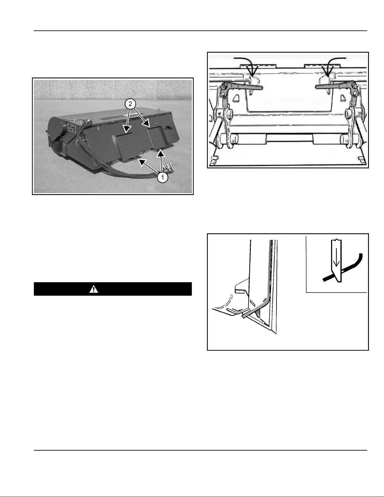
Inspecting The Attachment Mounting Frame
Figure 4
C208294a
Inspect the attachment wedge mounts (Item 1), mounting
flange (Item 2) [Figure 4], and all welds on the attachment
for wear and damage each time the attachment is
removed from the machine.
Frequently inspect the sweeper to ensure that all
components are secure, that all bolts and nuts are
thoroughly tightened, and that loose materials are not
wrapped around the bristles.
Inspecting The Machine Quick Coupler
WARNING
CRUSHING HAZARD
Failure to secure attachment coupler wedges can
allow attachment to come off and cause serious
injury or death.
Both wedges must extend through the holes in the
attachment mounting frame. Levers must be fully
down and locked.◂
W-2715-EF
Figure 5
NA3448a
• Lower down the quick coupler levers until they are
fully engaged in the locked position [Figure 5]
(wedges fully extended through the attachment
mounting frame holes).
The levers and wedges must move freely [Figure 5].
Figure 6
NA3450A
The wedges must extend through the holes in the
attachment mounting frame, securely fastening the
attachment to the machine quick coupler [Figure 6].
If the wedge does not contact the lower edge of the
hole, the attachment will be loose and can come off
the quick coupler.
OPERATING INSTRUCTIONS
12
Figure 7
NA13065S
• Inspect the attachment mounting frame.
(See Inspecting The Attachment Mounting Frame on
Page 11)
• Replace any parts that are damaged, bent, or
missing [Figure 7].
• Keep all fasteners tight.
• Look for cracked welds.
• Contact your Ignite Attachments representative for
replacement parts.
• Lubricate the wedges.
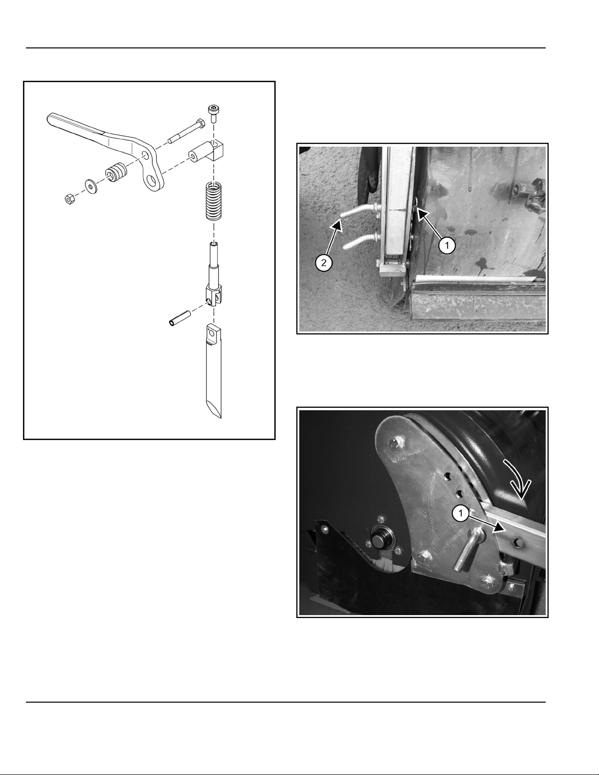
GUTTER BRUSH OPERATION (IF
EQUIPPED)
NOTE: The gutter brush kits are available for the right
side of the sweeper.
Figure 8
C210206a
1. Remove the retaining pin (Item 1)[Figure 8].
2. Remove the transport pin (Item 2) [Figure 8].
Figure 9
C210207a
3. Lower the gutter brush arm (Item 1) [Figure 9] into
the operating position.
4. Reinstall the transport pin (Item 2) and the retaining
pin (Item 1) [Figure 9] back to the original position for
OPERATING INSTRUCTIONS
13
storage when the gutter brush is in the lowered
position.
NOTE: Your attachment model kit may vary, but the
procedure is the same.
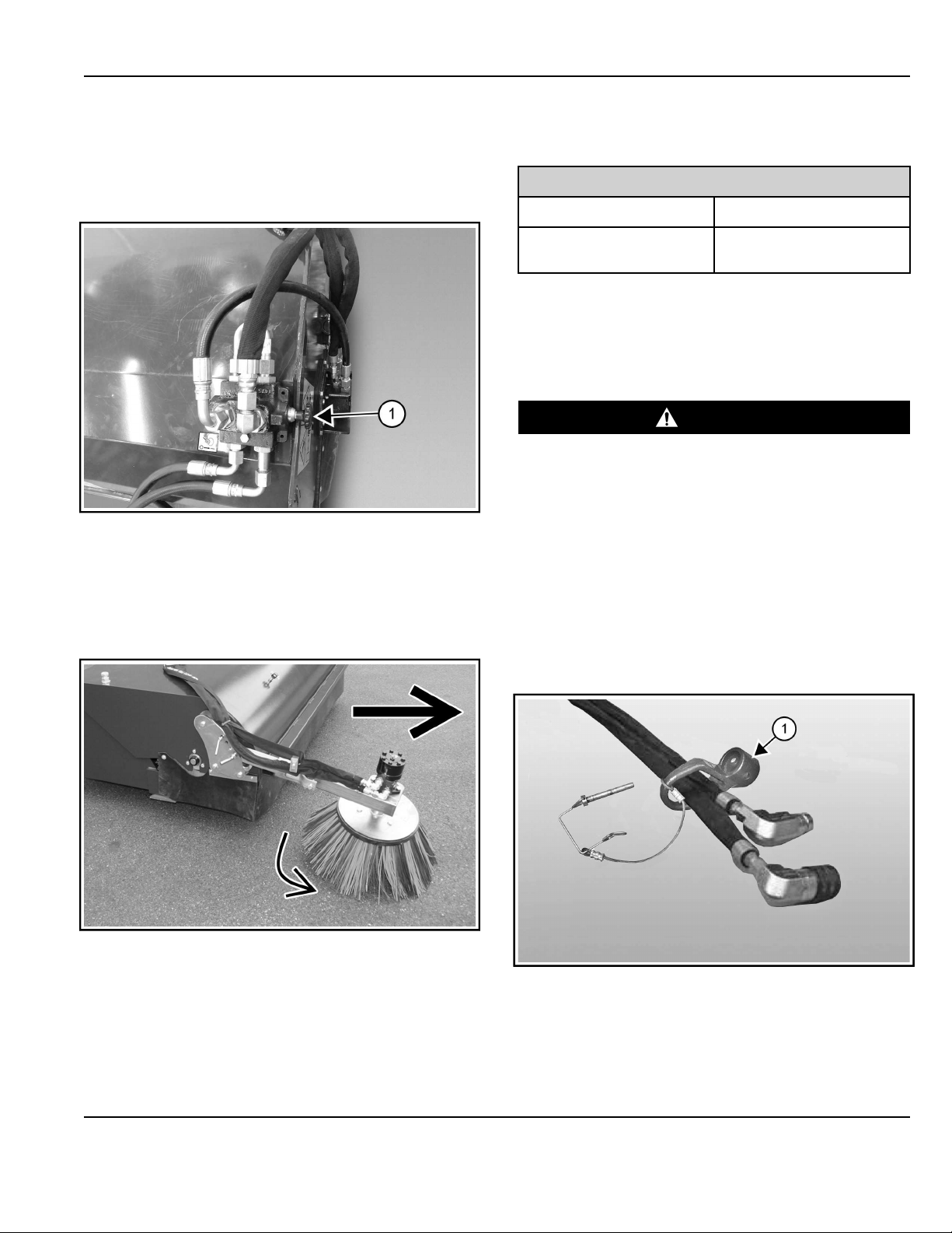
Figure 10
C208360a
5. Pull the knob (Item 1) [Figure 10] into the ON
position.
The gutter brush will start to turn with the sweeper
brush when the auxiliary hydraulics are engaged.
Figure 11
C210208a
6. The gutter brush is designed to sweep debris from a
curb or gutter out in front of the sweeper with the
sweeper in a forward travel direction [Figure 11].
NOTE: If the sweeper is used in the reverse mode
(scraping / sweeping) for any length of time, the
gutter brush should be turned off and lifted to the
transport position or removed from the sweeper.
OPERATING PROCEDURE WITH LOADERS
Approved Models And Requirements
Sweeper 72”
Hydraulic Flow 15.9 – 30.4 gal/min
Hydraulic Pressure
Range/Max
2466 – 3481 PSI
The chart shows the approved sweeper model for
machines based on hydraulic flow and pressure.
Warranty on this attachment is void if used on a non-
approved carrier. Contact your Ignite Attachments
representative for a current list of approved carriers.
WARNING
MODIFICATION AND INSUFFICIENT INSTRUCTIONS
HAZARD
Use of unapproved attachments / implements or
improperly sized attachments / implements can
cause serious injury or death.
Attachments / implements and buckets for safe loads
of specified densities are approved for each model.
Never use attachments / implements or buckets
which are not approved by . ◂
W-2709
Machine / Attachment Setup
Removable Hose Guide (If Equipped)
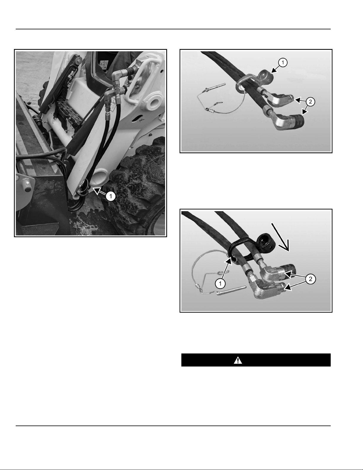
Figure 12
C213364a
Some attachments are factory equipped with a
removable hose guide (Item 1) [Figure 12] installed on
the hydraulic hoses. The removable hose guide is factory
installed for use with machines equipped with a mounting
post (Item 1) [Figure 13].
OPERATING INSTRUCTIONS
14
Figure 13
C213363c
Shown is the removable hose guide (Item 1) [Figure 12]
correct orientation for a machine.
NOTE: The removable hose guide orientation may need
to be changed for correct installation onto the
machine.
NOTE: If your machine is not equipped with a removable
hose guide post, the removable hose guide can
be removed from the hydraulic hoses.
Figure 14
C213364a
NOTE: If the couplers (Item 2) were removed, reinstall at
this time [Figure 14].
To change the removable hose guide (Item 1) [Figure 14]
orientation, slide the removable hose guide off the hoses.
Figure 15
P-88456a
NOTE: It may be necessary to remove the hose couplers
(Item 2) [Figure 15].
Entering And Exiting The Machine
WARNING
GENERAL HAZARD
Failure to follow instructions can cause serious
injury or death.
• Fasten seat belt, start, and operate only from the
operator’s seat.
• Never wear loose clothing when working near
machine.◂
W-2135
OPERATING INSTRUCTIONS
15
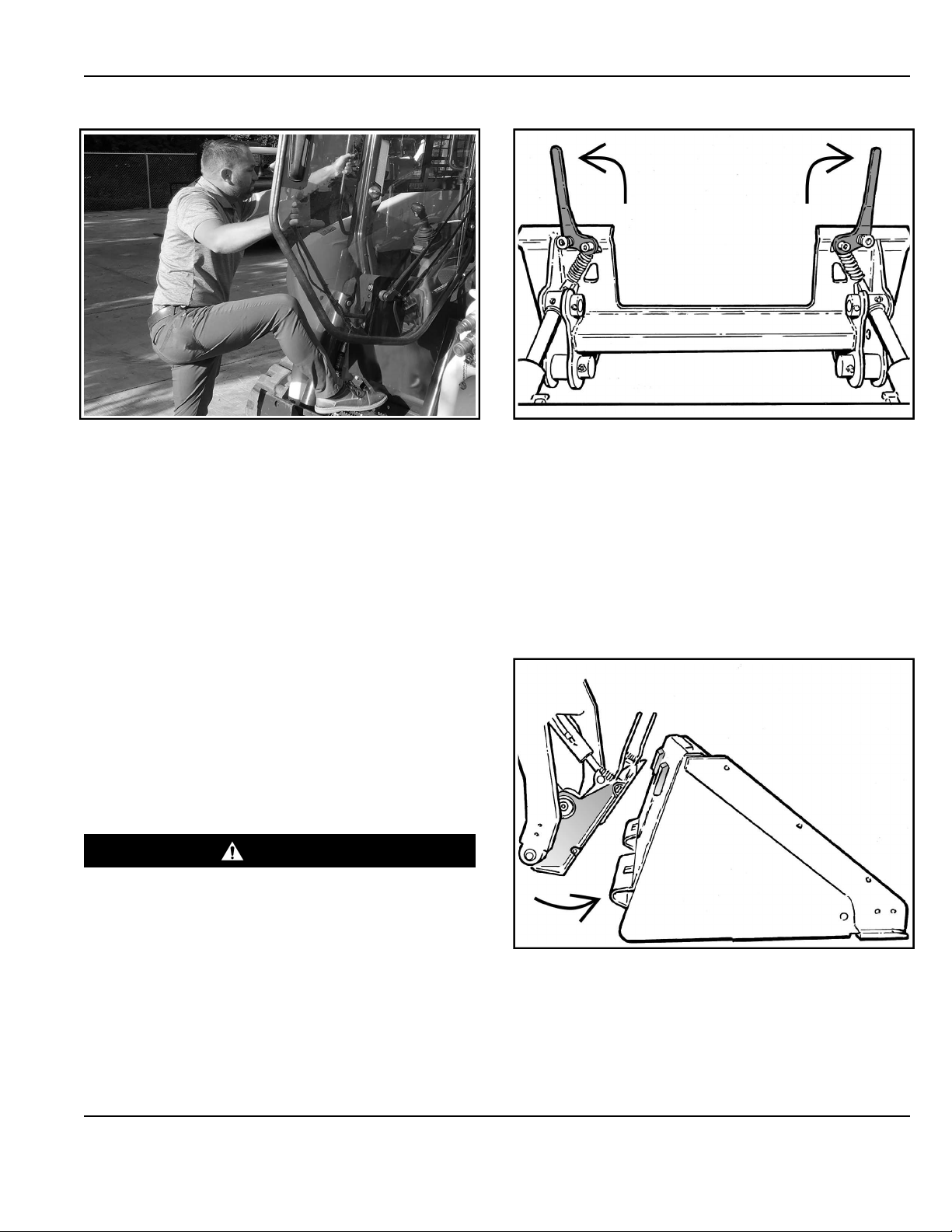
Figure 16
C216077a
• Use the attachment / implement steps (if equipped),
grab handles, and safety treads (on the machine and
frame) to get in and out of the machine, maintaining
a three-point contact at all times [Figure 16]. Do not
jump.
• See the machine’s Operation & Maintenance Manual
for detailed instructions on entering and exiting the
machine.
Installing The Attachment
Installing With Non-powered Machine Quick Coupler
The illustrations and instructions provided explain how to
install a bucket attachment onto a machine. Follow these
same instructions if you are installing different
attachments such as a grapple, snow pusher, sweeper,
etc.
The attachment mounting frame for the attachment has a
top flange that is designed to receive the top edge of the
machine quick coupler and the lower part of the frame is
designed to receive the quick coupler wedges.
WARNING
GENERAL HAZARD
Failure to obey warnings can cause serious injury or
death.
Obey all warnings on the machine and in the
manuals.◂
W-2744
Always inspect the machine’s quick coupler and the
attachment mounting frame before installation. (See the
machine’s Operation & Maintenance Manual.)
(See Daily Inspection on Page 11)
Figure 17
NA3445A
1. Pull the quick coupler levers up until they are fully
raised (wedges fully raised) [Figure 17].
2. Enter the machine.
3. Turn the machine on.
4. Release the parking brake.
5. Lower the lift arms and tilt the machine quick coupler
forward.
Figure 18
NA3446a
6. Drive the machine slowly forward until the top edge
of the quick coupler is completely under the top
flange of the attachment [Figure 18].
NOTE: Be sure the quick coupler levers do not hit
the attachment.
OPERATING INSTRUCTIONS

16
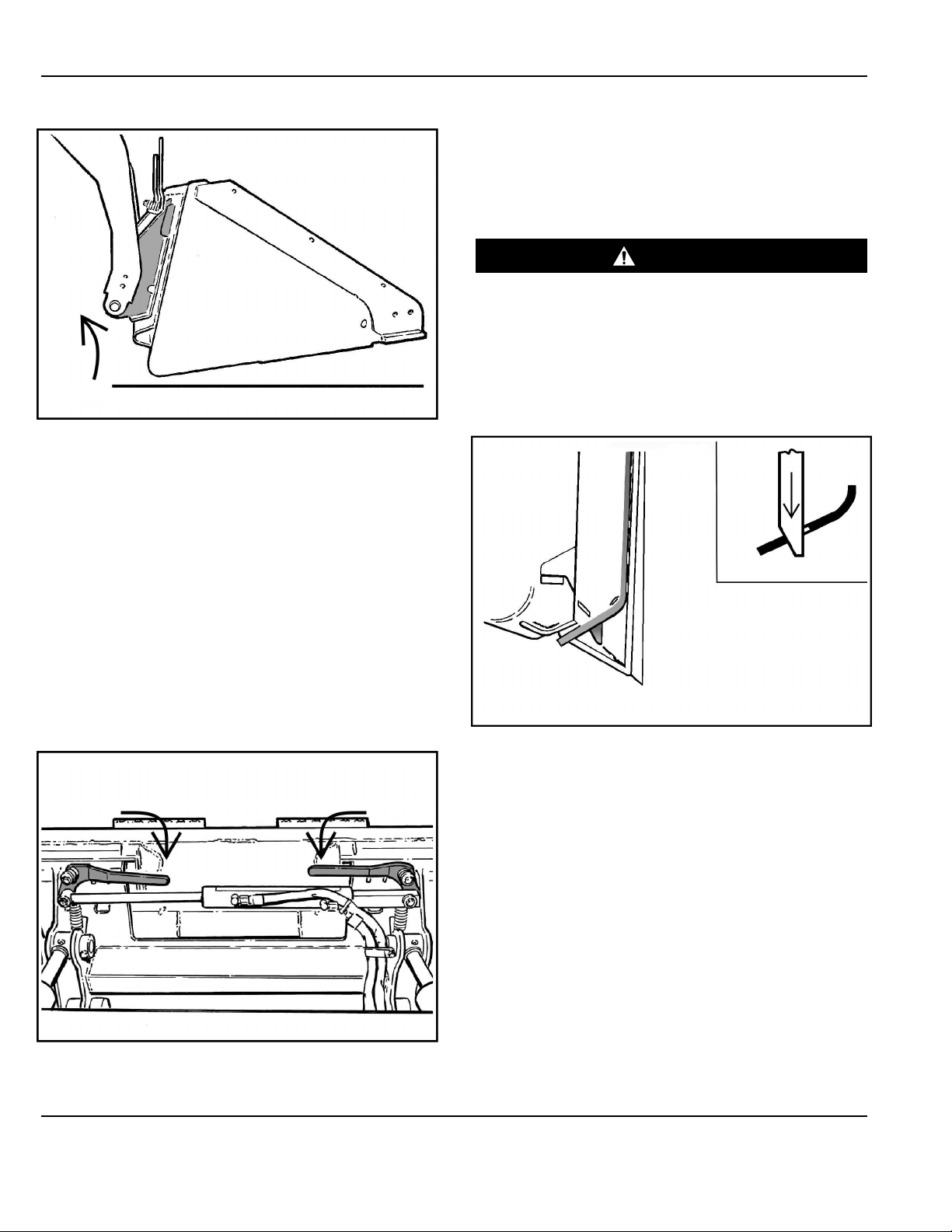
Figure 19
NA3447a
7. Tilt the quick coupler backward until the attachment
is slightly off the ground [Figure 19].
This will cause the attachment mounting frame to fit
up against the front of the quick coupler.
NOTE: When leaving the operator’s seat to install an
attachment, tilt the attachment until it is
slightly off the ground.
8. Turn the machine off and exit the machine.
WARNING
GENERAL HAZARD
Failure to follow instructions can cause serious
injury or death.
Before you leave the operator’s seat:
• Lower the lift arms and put the attachment /
implement flat on the ground.
• Engage the parking brake.
• Move all controls to the NEUTRAL / LOCKED
position to make sure the lift, tilt, and drive
functions are deactivated.
• Stop the engine.◂
W-3156
Figure 20
NA3448A
9. Push down on the quick coupler levers until they are
fully engaged in the locked position [Figure 20]
(wedges are fully extended through the attachment
mounting frame holes).
If both levers do not engage in the locked position,
see your machine dealer or representative for
maintenance.
OPERATING INSTRUCTIONS

17
WARNING
CRUSHING HAZARD
Failure to secure attachment coupler wedges can
allow attachment to come off and cause serious
injury or death.
Both wedges must extend through the holes in
the attachment mounting frame. Levers must be
fully down and locked.◂
W-2715-EF
Figure 21
NA3450A
The wedges must extend through the holes in the
attachment mounting frame, securely fastening the
attachment to the quick coupler [Figure 21].
Installing With Powered Machine Quick Coupler
WARNING
GENERAL HAZARD
Failure to obey warnings can cause serious injury or
death.
Obey all warnings on the machine and in the
manuals.◂
W-2744
Some machines may be equipped with a powered
machine quick coupler. For specific control location and
operation of the machine’s powered quick coupler, see
the machine’s Operation & Maintenance Manual.
1. Enter the machine.
2. Turn the machine on.
3. Release the parking brake.
Figure 22
NA3453A
4. Operate the powered quick coupler until the levers
are fully raised (wedges fully raised) [Figure 22].
5. Lower the lift arms and tilt the machine quick coupler
slightly forward.
Figure 23
NA3446a
6. Drive the machine slowly forward until the top edge
of the quick coupler is completely under the top
flange of the attachment mounting frame [Figure 23].
NOTE: Be sure the quick coupler levers do not hit
the attachment.
OPERATING INSTRUCTIONS
18
Figure 24
NA3447a
7. Tilt the quick coupler backward until the attachment
is slightly off the ground [Figure 24].
This will cause the attachment mounting frame to fit
up against the front of the quick coupler.
Some powered quick coupler system have
continuous pressurized hydraulic oil to keep the
wedges in the engaged position and prevent
attachment disengagement. Because the wedges
can slowly lower, the operator may need to
reactivate the powered quick coupler to be sure both
wedges are fully raised before installing the
attachment.
8. Operate the powered quick coupler until the levers
are fully raised (wedges fully raised).
Figure 25
NA3454A
9. Operate the powered quick coupler until the levers
are fully engaged in the locked position [Figure 25]
(wedges fully extended through the attachment
mounting frame holes).
If both levers do not engage in the locked position,
see your machine dealer or representative for
maintenance.
WARNING
CRUSHING HAZARD
Failure to secure attachment coupler wedges can
allow attachment to come off and cause serious
injury or death.
Both wedges must extend through the holes in the
attachment mounting frame. Levers must be fully
down and locked.◂
W-2715-EF
Figure 26
NA3450A
10. The wedges must extend through the holes
[Figure 26] in the attachment mounting frame,
securely fastening the attachment to the quick
coupler.
11. Lower the lift arms and put the attachment flat on the
ground.
12. Turn the machine off and exit the machine.
OPERATING INSTRUCTIONS
Table of contents


