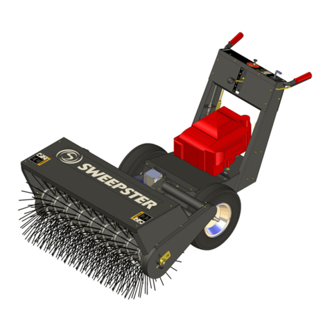
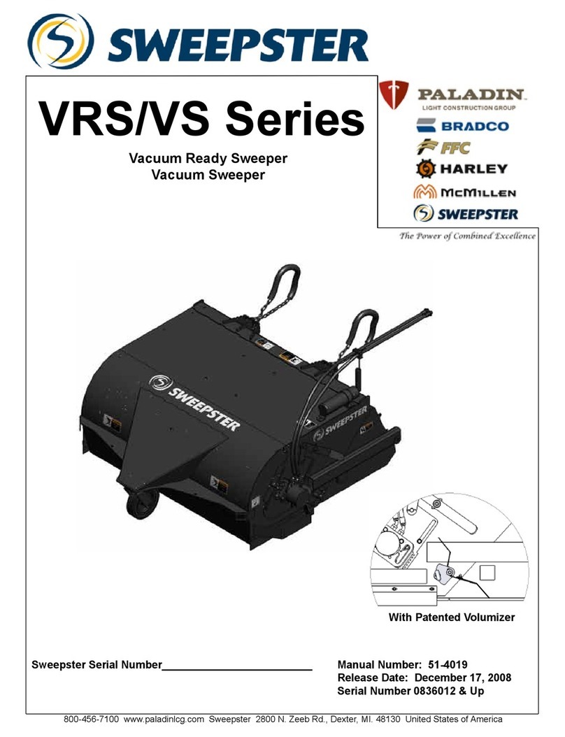
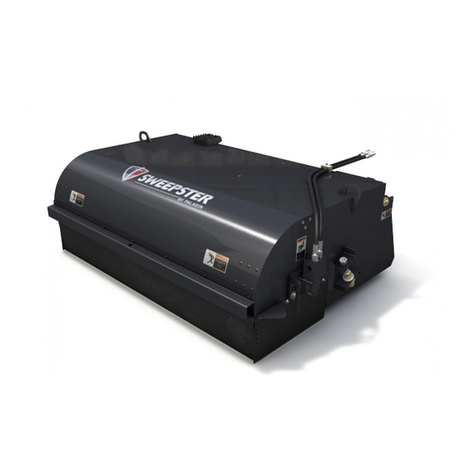
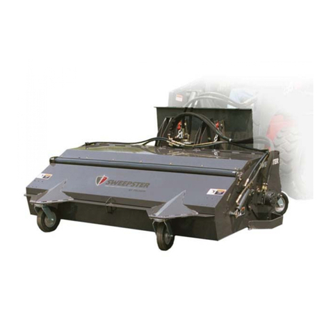
Sweepster VRS Series User manual

1
VRS/VS Series
Vacuum Ready Sweeper
Vacuum Sweeper
800-456-7100 www.paladinbrands.com Sweepster 2800 N. Zeeb Rd., Dexter, MI. 48130 United States of America
Sweepster Serial Number_________________________ Manual Number: 51-4019
Release Date: October 2006
Serial Number 0640001 & Up

2
Notes

3
TABLE OF CONTENTS
INTRODUCTION..........................................................................................................................................4
SAFETY STATEMENTS...............................................................................................................................4
GENERAL SAFETY PRECAUTIONS........................................................................................................5-6
SAFETY SIGNS & LABELS .........................................................................................................................7
SERVICE & REPAIR - SAFETY ...................................................................................................................8
OPERATION.................................................................................................................................................8
STORAGE ..................................................................................................................................................10
PRODUCT INFORMATION........................................................................................................................11
LUBRICATION POINTS .............................................................................................................................12
MAINTENANCE .........................................................................................................................................13
REPLACING BRUSH SECTIONS..............................................................................................................14
ATTACHING/ADJUSTING CHAINS ...........................................................................................................15
VOLUMIZER FEATURE .............................................................................................................................15
MAINTENANCE SCHEDULE.....................................................................................................................16
MAINTENANCE RECORD.........................................................................................................................17
TROUBLESHOOTING ..........................................................................................................................18-19
VRS RIGHT ASSEMBLY COMMON PARTS.........................................................................................20-21
VRS LEFT ASSEMBLY COMMON PARTS ...........................................................................................22-23
VRS BODY ASSEMBLY ........................................................................................................................24-26
VRS GUTTERBROOMS ......................................................................................................................28-31
VS RIGHT ASSEMBLY COMMON PARTS ...........................................................................................32-33
VS LEFT ASSEMBLY COMMON PARTS.............................................................................................34-35
VS BODY ASSEMBLY...........................................................................................................................36-38
HYDRAULIC ASSEMBLY MANIFOLDS................................................................................................40-42
VS GUTTERBROOMS .........................................................................................................................44-47
BOLT TORQUE SPECIFICATIONS ...........................................................................................................48
HYDRAULIC TORQUE SPECIFICATIONS...........................................................................................49-50
GLOSSARY...........................................................................................................................................51-52
WARRANTY ..........................................................................................................................................53-54

4
INTRODUCTION
Purpose of Sweeper
This sweeper is designed solely for the use in
construction cleanup, road maintenance and similar
operations. Use in any other way is considered
contrary to the intended use. Compliance with and
strict adherence to operation, service and repair
conditions, as specied by the manufacturer, are
also essential elements of the intended use.
Contacting Sweepster
If you have any questions about information in this
manual or need to order parts, please call, write, fax
or e-mail SWEEPSTER.
Sweepster
2800 North Zeeb Road
Dexter, Michigan 48130
Phone: (734)-996-9116 - (800)-456-7100
Fax: (734) 996-9014
e-mail: [email protected]
For help with installation, operation or maintenance
procedures, contact our Technical Service
Department. Direct product questions and parts
orders to our Sales Department.
When ordering parts or accessories, be prepared to
give the following information:
• Sweeper model, serial number and date of
purchase
• Prime mover, make and model
• Part number, description and quantity
Terms Used in Manual
Right-hand, left-hand, front and rear are determined
from the operator’s perspective (either the
operator’s seat or standing behind a walk-behind
unit), facing forward in the normal operating
position.
Warranty
To validate the warranty for this unit, ll out the
warranty card or warranty pages located in the
back of this manual. Then send this information to
SWEEPSTER.
SAFETY STATEMENTS
DANGER THIS SIGNAL WORD IS USED
WHERE SERIOUS INJURY OR
DEATH WILL RESULT IF THE
INSTRUCTIONS ARE NOT
FOLLOWED PROPERLY.
WARNING THIS SIGNAL WORD IS USED
WHERE SERIOUS INJURY OR
DEATH COULD RESULT IF
THE INSTRUCTIONS ARE NOT
FOLLOWED PROPERLY.
CAUTION THIS SIGNAL WORD IS USED
WHERE MINOR INJURY COULD
RESULT IF THE INSTRUCTIONS
ARE NOT FOLLOWED PROPERLY.
NOTICE THIS SIGNAL WORD IS USED
WHERE EQUIPMENT OR
PROPERTY DAMAGE COULD
RESULT IF THE INSTRUCTIONS
ARE NOT FOLLOWED PROPERLY.
THIS SYMBOL BY ITSELF OR
USED WITH A WARNING WORD
THROUGHOUT THIS MANUAL IS
USED TO CALL YOUR ATTENTION
TO INSTRUCTIONS INVOLVING
YOUR PERSONAL SAFETY
OR THE SAFETY OF OTHERS.
FAILURE TO FOLLOW THESE
INSTRUCTIONS CAN RESULT IN
INJURY OR DEATH.

5
GENERAL SAFETY PRECAUTIONS
WARNING READ MANUAL PRIOR TO
INSTALL
Improper installation, operation,
or maintenance of this equipment
could result in serious injury or
death. Operators and maintenance
personnel should read this
manual as well as all manuals
related to this equipment and the
prime mover thoroughly before
beginning installation, operation,
or maintenance. FOLLOW ALL
SAFETY INSTRUCTIONS IN
THIS MANUAL AND THE PRIME
MOVERS MANUAL.
WARNING READ AND UNDERSTAND ALL
SAFETY STATEMENTS
Read all safety decals and safety
statements in all manuals prior
to operating or working on this
equipment. Know and obey all
OSHA regulations, local laws
and other professional guidelines
for your operation. Know and
follow good work practices when
assembling, maintaining, repairing,
mounting, removing or operating this
equipment.
KNOW YOUR EQUIPMENT
Know your equipment’s capabilities,
dimensions and operations before
operating. Visually inspect your
equipment before you start, and
never operate equipment that is not
in proper working order with all safety
devices intact. Check all hardware to
assure it is tight. Make certain that all
locking pins, latches, and connection
devices are properly installed and
secured. Remove and replace any
damaged, fatigued or excessively
worn parts. Make certain all safety
decals are in place and are legible.
Keep decals clean, and replace them
if they become worn and hard to
read.
GENERAL SAFETY PRECAUTIONS
WARNING PROTECT AGAINST FLYING
DEBRIS
Always wear proper safety glasses,
goggles or a face shield when driving
pins in or out or when operation
causes dust, ying debris, or any other
hazardous material.
WARNING LOWER OR SUPPORT RAISED
EQUIPMENT
Do not work under raised booms
without supporting them. Do not use
support material made of concrete
blocks, logs, buckets, barrels or any
other material that could suddenly
collapse or shift positions. Make sure
support material is solid, not decayed,
warped, twisted, or tapered. Lower
booms to ground level or onto blocks.
Lower booms and attachments to
the ground before leaving the cab or
operator’s station.
WARNING USE CARE WITH HYDRAULIC FLUID
PRESSURE
Hydraulic uid under pressure can
penetrate the skin and cause serious
injury or death. Hydraulic leaks
under pressure may not be visible.
Before connecting or disconnecting
hydraulic hoses, read your prime
movers operator’s manual for detailed
instructions on connecting and
disconnecting hydraulic hoses or
ttings.
• Keep unprotected body parts,
such as face, eyes, and arms as far
away as possible from a suspected
leak. Flesh injected with hydraulic
uid may develop gangrene or
other permanent disabilities.
• If injured by injected uid, see a
doctor at once. If your doctor is not
familiar with this type of injury, ask
him to research immediately to
determine proper treatment.

6
WARNING DO NOT MODIFY MACHINE OR
ATTACHMENTS
Modications may weaken the
integrity of the attachment and may
impair the function, safety, life and
performance of the attachment.
When making repairs, use only
the manufacturer’s genuine parts,
following authorized instructions.
Other parts may be substandard
in t and quality. Never modify
any ROPS (Roll Over Protection
System) equipment or device. Any
modications must be authorized in
writing by the manufacturer.
GENERAL SAFETY PRECAUTIONS
CONTINUED
WARNING - SAFELY MAINTAIN AND REPAIR
EQUIPMENT
• Do not wear loose clothing, or any
accessories that can catch in
moving parts. If you have long hair,
cover or secure it so that it does
not become entangled in the
equipment.
• Work on a level surface in a well-lit
area.
• Use properly grounded electrical
outlets and tools.
• Use the correct tool for the job at
hand. Make sure they are in good
condition for the task required.
• Wear the protective clothing
equipment specied by the tool
manufacturer.
WARNING - SAFELY OPERATE EQUIPMENT
Do not operate equipment until you
are completely trained by a qualied
operator in how to use the controls,
know its capabilities, dimensions,
and all safety requirements. See
your prime movers manual for these
instructions.
• Keep all step plates, grab bars,
pedals, and controls free of dirt,
grease, debris, and oil.
• Never allow anyone to be around
the equipment when it is operating.
• Do not allow riders on the
attachment or the prime mover.
• Do not operate the equipment
from anywhere other than the
correct operators position.
• Never leave equipment unattended
with the engine running or with this
attachment in a raise position.
• Do not alter or remove any safety
feature from the prime mover or
this attachment.
• Know your work site safety rules as
well as trafc rules and ow. When
in doubt on any safety issue,
contact your supervisor or safety
coordinator for an explanation.
• Wear safety glasses, protective
clothing, and use a sound piece of
cardboard or wood when
searching for hydraulic leaks.
DO NOT USE YOUR HANDS!
SEE ILLUSTRATION.
GENERAL SAFETY PRECAUTIONS
CONTINUED

7
SAFETY SIGNS & LABELS
There are several specic signs on this sweeper.
The exact location of the hazards and description of
the hazards are reviewed.
Placement or replacement of Safety Signs
1. Clean the area of application with nonammable
solvent, and then wash the same area with soap
and water.
2. Allow the surface to fully dry.
3. Remove the backing from the safety sign,
exposing the adhesive surface.
4. Apply the safety sign to the position shown in
the diagram above and smooth out any bubbles.
Instructions
1. Keep all safety signs clean and legible.
2. Replace all missing, illegible, or damaged safety
signs.
3. Replacement parts, for parts with safety signs
attached, must also have safety signs attached.
4. Safety signs are available, free of charge, from
your dealer or from SWEEPSTER.
50-0634 50-0643
Item Part Qty Description
1. 50-0634 1 Label, Serial Number
2. 50-0643 2 Label, Tie Down Point
3. 50-0723 1 Label, Warning, Misuse Hazard
4. 50-0724 1 Label, Warning, High Pressure Fluid
5. 50-0727 3 Label, Warning, Flying Objects
6. 50-0737 2 Label, Warning, Pinch Point Hazard
5
2
46
3
51
6
25
SAFETY LABELS
50-0723
50-0724
50-0727
50-0737

8
SERVICE & REPAIR - SAFETY
CAUTION - DO NOT MODIFY THE SWEEPER
IN ANY WAY. Personal injury could
result. If you have questions, contact
your dealer or SWEEPSTER.
Repair or adjust the sweeper in a safe area, away
from trafc and other hazards.
Before adjusting or servicing the sweeper, lower
the sweeper to the ground, stop the prime mover
engine, set the brakes and remove the key from the
ignition.
When working on or around the sweeper, lower it
to the ground or secure it with transport chains or
cylinder-stop locks.
Stop the prime mover engine and cycle control
levers to release hydraulic pressure before servicing
or adjusting sweeper hydraulic systems.
WARNING - ESCAPING HYDRAULIC FLUID can
have enough pressure to penetrate
the skin, causing serious personal
injury.
Do not bend high pressure lines. Do not strike high
pressure lines. Do not install bent lines, bent tubes,
or kinked hoses. Do not install damaged lines,
tubes, or hoses.
Repair damaged or loose lines, tubes and hoses.
Leaks can cause res. See your SWEEPSTER
dealer for repair or replacement parts.
Replace the parts if any of the following conditions
are present:
• The end ttings are damaged or leaking.
• The outer covering is chafed or cut.
• The reinforcing wire layer is exposed.
• The outer covering is ballooning locally.
• The hose is kinked or crushed.
• The hose has been pulled or stretched.
Make sure that all clamps, guards, and shields are
installed correctly.
OPERATION
CAUTION - A SWEEPER IS A DEMANDING
MACHINE. Only fully trained
operators or trainee operators under
supervision of a fully trained person
should use this machine.
Before operating sweeper:
•Learn sweeper and prime mover controls in an
off-road location.
•Be sure that you are in a safe area, away from
trafc or other hazards.
•Check all hardware holding the sweeper to the
host machine, making sure it is tight.
•Replace any damaged or fatigued hardware
with properly rated fasteners.
•Make sure all hydraulic hardware and hydraulic
ttings are tight.
•Replace any damaged or fatigued ttings or
hoses.
•Check all tire pressures before sweeping.
•Check tire ratings to be sure they match the
prime mover load. Weigh the sweeper end of
the prime mover, if necessary, to insure proper
tire rating.
•Remove from the sweeping area all property
that could be damaged by ying debris.
•Be sure all persons not operating the sweeper
are clear of the sweeper discharge area.
•Always wear proper apparel such as a long
sleeved shirt buttoned at the cuffs; safety
glasses, goggles or a face shield; ear
protection; and a dust mask.
While operating sweeper:
•When operating sweeper, adhere to all
government rules, local laws and other
professional guidelines for your sweeping
application.

9
Run the prime mover and sweeper at a low idle.
Check for hydraulic leaks or other problems and
make corrections, if necessary, before using the
sweeper.
WARNING - AVOID SERIOUS INJURY. Check
for large objects that could harm the
operator or others if thrown by the
sweeper. Remove these items before
operating.
During Use
Carry the sweeper low to the ground so that the
operator has good visibility and stability. Avoid any
sudden movements from one side to the other side
when you carry a sweeper.
Avoid excessive downward pressure on the brush
sections to prevent excessive wear. A two to six
inch wide pattern is sufcient for most applications.
Ensure that the motor and bearing plates are
equally adjusted in order to prevent an uneven wear
pattern.
Directing Debris
Observe wind direction. Sweeping with the wind
makes sweeping more effective and helps keep
debris off the operator.
The terms swing and angle are used
interchangeably.
NOTICE - AVOID SWEEPER DAMAGE.
Reduce travel speed to avoid hitting
immovable objects.
•Before leaving the operators area for any
reason, lower the sweeper to the ground. Stop
the prime mover engine, set the brakes and
remove the key from the ignition.
•Minimize ying debris - use the slowest rotating
speed that will do the job.
•Keep hands, feet, hair and other loose clothing
away from all moving parts.
•Leave the brush hood (shield) and all other
shields and safety equipment in place when
operating the sweeper and primer mover.
•Be aware of extra weight and width a sweeper
adds. Reduce travel speed accordingly.
•Leave the brush hood (shield) and all other
shields and safety equipment in place when
operating the sweeper.
•When sweeping on rough terrain, reduce speed
to avoid “bouncing” the sweeper. Loss of
steering can result.
•Never sweep toward people, buildings, vehicles
or other objects that can be damaged by ying
debris.
•Only operate the sweeper while you are in the
seat of the prime mover. The seat belt must be
fastened while you operate the prime mover.
Only operate the controls while the engine is
running. Protective glasses must be worn while
you operate the prime mover and while you
operate the sweeper.
•While you operate the sweeper slowly in an
open area, check for proper operation of all
controls and all protective devices. Note any
repairs needed during operation of the sweeper.
Report any needed repairs.
Before Each Use
Perform daily maintenance as indicated in
Maintenance Schedule.

10
Brush, Engine & Travel Speeds
Vary brush, engine and travel speeds to match
sweeping conditions.
Large Areas
When sweeping a large area, such as a parking lot,
make a path down the middle and sweep to both
sides. This reduces the amount of debris that the
sweeper must sweep to one side.
Snow
Fast brush speeds and slow travel speeds are
needed to sweep effectively. Start at 3/4 throttle and
the lowest gear of the prime mover. For wet and/or
deep snow, increase to almost full throttle. This
helps keep snow from packing up inside the brush
hood.
In deep snow you may need to make multiple
passes to get down to a clean surface.
To keep snow from blowing back onto a swept area,
always sweep so the wind is at your back.
Dirt & Gravel
To keep dust at a minimum, plan sweeping for days
when it is overcast and humid or after it has rained.
Also, sweep so the wind blows at your back.
Low brush speeds and moderate travel speeds work
best for cleaning debris from hard surfaces. Brush
speeds that are too fast tend to raise dust because
of the aggressive sweeper action.
To sweep gravel, use just enough brush speed to
“roll” the gravel, not throw it.
Heavy Debris
Travel slowly - 1-2 mph.
Sweep a path less than the full width of the
sweeper.
Increase engine speed if debris becomes very
heavy.
STORAGE
NOTICE Do not store the sweeper with
weight on the brush. Weight will
deform the bristles, destroying the
sweeping effectiveness.
Do not store polypropylene
brushes in direct sunlight. The
material can deteriorate and crumble
before the bristles are worn out.
Keep polypropylene brush
material away from intense heat or
ame.

11
Specications and Model Views
PRODUCT INFORMATION
Maximum Weight with
Bucket
1201 lbs ( VRS 60 )
1294 lbs ( VRS 72 )
1385 lbs ( VRS 84 )
Actual Sweeping Width
60 inches ( VRS 60 )
72 inches ( VRS 72 )
84 inches ( VRS 84 )
Maximum Length 69 inches ( all models )
Maximum Width
72 inches ( VRS 60 )
85 inches ( VRS 72 )
97 inches ( VRS 84 )
Maximum Hydraulic
Oil Flow
25 gpm
Maximum Hydraulic
Oil Pressure
3000 psi
5 FT.
73.1
69.8
Maximum Length
Maximum Width

12
LUBRICATION POINTS
The following grease ttings should be greased
before each use. See gure for locations.
1. Caster ( 2 ttings)
2. Bucket Pivot ( 1 Fitting each )
2
1

13
MAINTENANCE
Brush Pattern
A properly adjusted brush offers the best sweeper
performance. To check the brush pattern:
1. Move the sweeper to a dusty, at surface.
2. Set the prime movers parking brake and leave
the engine running.
3. Start the sweeper at a slow speed; then, lower it
so the boom arms bottom out. Run the sweeper
in a stationary position for 10 seconds.
4. Raise the sweeper and back away; switch off
the engine and remove the key from the prime
mover. The brush pattern left in the dust should
be 2-6 inches wide, running the length of the
brush. (gure 1)
5. Adjust the brush pattern as necessary according
to the following instructions.
a. If the brush pattern is too wide, pull the “T”
handle quick pin and move it up one notch.
Repeat on the opposite side.
b. If the brush pattern is too narrow, pull the
“T” handle quick pin and move it down one
notch. Repeat on the opposite side.
c. Use the sight indicator to be sure sweeper
brush is level at all times.
6. Repeat steps # 1 through #5 until the brush
pattern is 2-6 inches wide.
Swept Area
2-6 inches
gure 1
“T” handle quick pin
Sight Indicator

14
REPLACING BRUSH SECTIONS
1. Remove four motor mount screws. Retain
hardware for reinstallation. Remove motor
mount.
2. Detach four bearing mount screws from side
plate. Retain hardware for reinstallation.
3. Lift sweeper body leaving core on ground.
4. Remove the core hat plate. Retain hardware for
reinstallation.
5. Remove old sections.
6. Install new sections by doing the following:
a. Number the tubes on the core as 1,2 and 3
(gure 1).
b. Slide the rst section onto the core with the
drive pins on either side of tube 1. Make
sure that the drive pins angle up (gure 1).
c. Place the second section on the core with
the drive pins on either side of tube 2. Be
sure the drive pins angle down (gure 2).
d. Put the third section on with the drive pins
around tube 3. Be sure the drive pins angle
up.
e. Slide sections on until the core is full, making
sure to alternate the tubes used and the
direction of the drive pins.
7. Re-attach the core hat plate.
8. Lay core on ground. Lower body over core.
9. Re-attach the bearing plate with previously
removed hardware.
10. Attach motor mount with hardware removed in
step one.
gure 1
gure 2
F ir s t S ect ion
Second S ect ion

15
ATTACHING CHAINS
1. Install the sweeper to the prime movers quick
attach mounting.
2. Attach chains to SSL grab bars using one 5/16
quick link.
3. Attach chains to sweeper using one 5/16 wide
jaw quick clip per side. (gure 1) Leave the
chains loose with equal slack in both sides. Do
not entangle hydraulic hoses.
4. Connect hydraulic hoses to prime mover remote
hydraulics.
CAUTION - AVOID EQUIPMENT DAMAGE AND
PERSONAL INJURY. Chains must
be of equal length and long enough
to keep the sweeper level during
dumping. Short chains may cause
the sweeper body to tip back and
damage the sweeper body.
ADJUSTING CHAINS
1. Make sure chains are quite loose
2. Raise the sweeper and then dump the bucket
slowly. The sweeper will dump correctly if chains
have the proper tension. If the sweeper tips
down when test dumping, go to step 3.
3. Tighten both chains by the same amount but no
more than two links each.
4. Repeat steps 2 and 3 until the sweeper dumps
correctly.
gure 1
VOLUMIZER FEATURE
The Volumizer is designed to allow the level of
debris to be controlled in the hopper and to prevent
carry over of material.
VOLUMIZER ADJUSTMENT
As brush sections wear, the volumizer can be
adjusted by pulling the “T” handle quick pin and
moving it down one notch.
VOLUMIZER REMOVAL
To remove volumizer for pan sweeping, remove
M10 screw and mounting pin from bearing side,
then remove M6 screw and weld handle on motor
side. Next, secure bucket and lift body to pull out
volumizer.

16
MAINTENANCE SCHEDULE
Procedure Before
Each
Use
After
Each
Use
100
Hours
500
Hours
See Prime
Mover
Manual
Brush pattern - Check (See Brush Pattern)
Fittings/hoses, hydraulic - Tighten
-Check for damage
Fittings, zerk - Grease (See Lubrication Points)
Oil, hydraulic (Prime Mover)- Check Level
- Check Cleanliness
Hardware -Tighten
Oil Cleanliness Requirements
NOTICE - All hydraulic uid shall be ltered
before use in any SWEEPSTER
product to obtain the ISO cleanliness
standard of 17-14 or better, unless
explicitly specied otherwise.

17
MAINTENANCE RECORD
Date Maintenance Procedure Performed Performed by Comments

18
TROUBLESHOOTING
Problem Possible Cause
Motor for pick-up broom will not operate Auxiliary hydraulics control on prime mover
is activated in the wrong position
Hoses improperly connected to prime mover
Hoses on prime mover are obstructed
Hoses on broom are obstructed
The motor has failed
Sluggish broom operation Insufcient oil ow from the prime mover
One or more seals have failed in the motor
Hydraulic lter on prime mover is dirty
The motor runs but the broom does not run Motor shaft has a sheared key
Oil leaks from the motor One or more seals have failed in the motor
Seals on the ttings are damaged
Fittings are loose or damaged
Hydraulic hoses are loose or damaged
Brush rotates in wrong directions Hoses installed incorrectly
Brush slows or stops when sweeping Brush pattern too wide
Travel speed too fast
Trying to sweep too much material at once.
Hydraulic motor is failing
Brush wears very quickly Brush pattern is too wide
Brush Head Assembly

19
TROUBLESHOOTING
Problem Possible Cause
Excessive hydraulic oil temperature Low hydraulic oil level on the prime mover
Hydraulic hoses are obstructed
Hydraulic oil is dirty
Quick couplers are loose
Hydraulic quick coupler leaks Quick coupler poppet is unseated
Hydraulic Assembly

20
Item Part Qty Description
1. 03-1939 2 Fitting, Adapter, 7/8MOR, 5/8MFS
2. 03-5087 1 Motor, Hydraulic, White, 28.3 CI
3. 03-5224 2 Hose, 1/2 x 96, 10MOR, 10FFS45
4. 07-0156 12 Washer, Flat, Gr8, 1/2
5. 07-0244 8 Pin, Linch, 1/4
6. 07-1044 2 Pin, Cotter, Gr2, 5/32 x 1 1/2
7. 07-1714 1 Screw, HHC, Gr8, 5/16-18 x 1
8. 07-1784 1 Screw, HHC, Gr8, 5/16-18 x 2 1/2
9. 07-2840 2 Chain, 1/4, 56 Links, Gr43
10. 07-2950 3
Bolt,
Carriage, CL8.8, M8-1.25 x 20mm
11. 07-2952 13 Screw, HFH, CL10.9, M6-1 x 20
12. 07-3112 2 Fitting, Zerk, 1/4-28, Self Tap
13. 07-3273 1 Washer, Lock, Split, Medium, 5/16
14. 07-3311 2 Link, Quick, 5/16
15. 07-3617 3 Nut, Insert, Hex, M6 x 1
16. 07-3708 2 Bolt, Carriage, Gr5, 1/2-13 x 1 1/2
17. 07-3709 2 Bolt, Carriage, Gr5, 1/2-13 x 1 3/4
18.* 07-3734 1 Screw, HHC, CL10.9, M6-1 x 45mm
19. 07-3737 6 Nut, Hex, CL10, M8-1.25
20. 07-3738 6 Washer, Lock, Split, Medium, M8
21.** 07-3745 5 Washer, Flat, CL8.8, M10
22.*** 07-3747 25 Washer, Lock, Split, Medium, M10
23.*** 07-3749 19 Screw, HHC, CL10.9, M10-1.5 x
30mm
24. 07-3754 3 Washer, Flat, CL8.8, M12
25. 07-3756 3 Washer, Lock, Split, Medium, M12
26. 07-4037 4 Nut, Hex, Nylock, Gr8, 1/2-13
27. 07-4040 1 Washer, Flat, Gr8, 1
28. 07-4228 6 Washer, Flat, CL8.8, M14
29.* 07-4604 1 Nut, Hex, Lock, ST, CL10.9,
M8-1.25
30. 07-4942 2 Washer, Fender, 1 1/2 x 5/16
31. 07-5933 4 Bolt, Carriage, CL8.8, M8-1.25 x
5mm
32. 07-6196 1 Ring, Retaining, 2.75
33. 07-6521 1 Plate, Shim, 1/4
34. 07-6682 1 Nut, Insert, M10-1.5
35. 07-6683 3 Screw, HHC, Cl10.9, M12-1.75 x
65mm
36. 07-6766 3 Nut, Hex, CL10.9, M12-1.75
37. 07-6769 6
Screw,
HHC,
CL10.9, M10-1.5 x16mm
38. 07-6798 1 Caster, Assembly, 10 x 2.75
39. 07-7024 4 Washer, Belleville, 1.063 x 1.496
40. 08-0008 2 Bearing, Flange, 3 Bolt
41. 08-0037 1 Bearing, 7/8 Hex, without Hub
42. 09-0066 4ft Hose, LP, 1 Fiber Braid
43. 13-10060 12 Finger, Apron
44. 13-11734 2 Weld, Pin, 1 x 8
45. 13-12750 1 Weld, Hex, Plate, with Doubler
46. 13-13453 1 Plate, Core, Hat
47. 13-14058 1 Hub, Hex, 2 1/2 x 1 1/4 Tapered
Bore x 3.56
48. 13-14083 6 Stud, Mounting, Motor
49. 13-14086 1 Plate, Handle, Motor
50.* 13-14187 1 Weld, Mounting, Volumizer
51. 13-15223 4 Tube, Round, 1 x .562 x .375
52. 13-15246 2 Plate, Handle, Adjustment
53. 13-15247 8 Tube, Round, 5/8 x 11ga x .312
54. 13-15248 1 Weld, Mounting, Motor, Core, Left
55. 13-15249 1 Weld, Mounting, Motor, Core, Right
56.* 13-15260 1 Weld, Handle, Volumizer
57. 13-15262 2 Plate, Link, Adjustment, Motor
58. 13-15263 1 Plate, Mounting, Core
59. 13-15264 1 Plate, Mounting, Motor
60. 13-15265 2 Flap, Side
61. 13-15267 2 Plate, 1/8 x 1 1/4 x 23.5, with Slots
62. 13-15398 1 Tube, Round, 1 1/2 x 7/32 x 1.1
63. 50-0185 2 Label, Logo, Sweepster, Medium
64. 50-0252 1 Label, Logo, Sweepster, Large
65. 50-0768 1 Label, Volumizer
66. LAF9853 12 Plug, .375, Black Plastic
67. RHW8613 1 Weld, Plate
68. RHW8614 1 Cover, Plate
69. RHW8616 1 Hose, Cradle
70. RHW8618 1 Hose, Spring
71. RHW8642 9 Nut, Rivet, 5/16-18, .15-.312 Grip
72. RHW8645 4 Nut, Rivet, 5/16-18, .027-.15 Grip
Required for Non-Volumizer Units Only
73. 07-4514 4 Nut, Hex, CL10, M10-1.5
74. 13-19205 2 Plate, Cover, Adjustment
Item Part Qty Description
VRS RIGHT ASSEMBLY COMMON PARTS
* Not Required on Non-Volumizer Units
** (1) Less Required on Non-Volumizer Units
*** (3) Less Required on Non-Volumizer Units
Other manuals for VRS Series
1
This manual suits for next models
1
Table of contents
Other Sweepster Blower manuals

Sweepster
Sweepster TB Series User manual

Sweepster
Sweepster WSP36 series User manual

Sweepster
Sweepster VRS Series User manual

Sweepster
Sweepster WSP36 series Product manual

Sweepster
Sweepster QC 210 Series User manual

Sweepster
Sweepster 240 series User manual

Sweepster
Sweepster 205 Series Product manual

Sweepster
Sweepster CS Series User manual

Sweepster
Sweepster WSP24 User manual