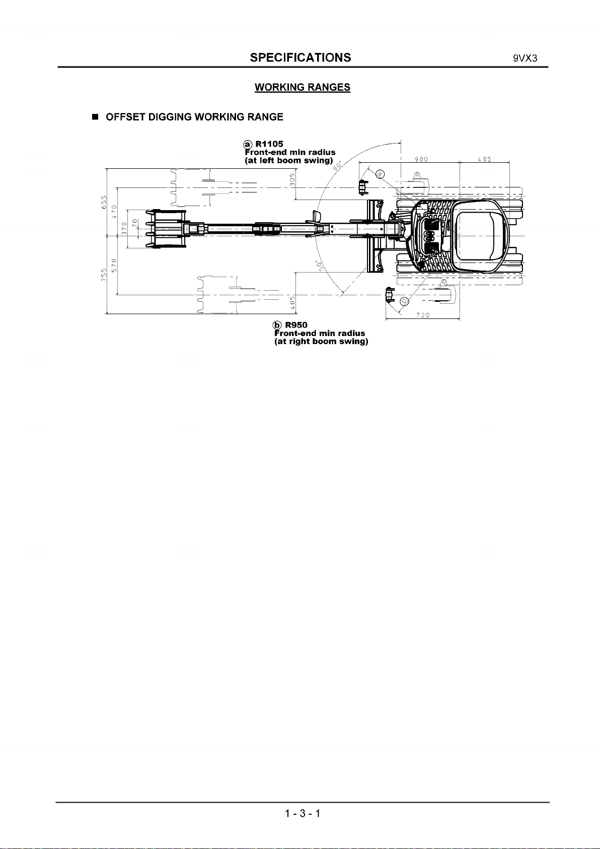
IHI 9VX3 User manual

Service Guide
9VX3
I H I
SERIAL NUMBERS
WB004001- up
UB. No.1
1205

9VX3
HYDRAULIC MINI EXCAVATOR
- TABLE OF CONTENTS -
SECTION 1
..................................
S ECIFICATIONS
SECTION 2
..................................
STRUCTURE AND FUNCTION
SECTION 3
..................................
O ERATION
SECTION 4
..................................
MAINTENANCE
SECTION 6 ERFORMANCE STANDARDS

9VX3
SECTION 1 S ECIFICATIONS
TABLE OF CONTENTS
Subject page
General Speci ications
................................................................................................
1-1-1
Overall Dimensions
.....................................................................................................
1-2 - 1
Working Ranges
...........................................................................................................
1-3-1
Weight Breakdown
......................................................................................................
1-4-1
Painting Diagram
...........................................................................................................
1-5-1
Engine Main Date and Speci ications
......................................................................
1-6-1
Li ting Capacities Table
................................................................................................
1-7-1
Sa ety Signs and Labels
.............................................................................................
1-8-1

S ECIFICATIONS 9VX3
GENERAL S ECIFICATIONS
■ BASE MACHINE ERFORMANCE
Swing speed min' 1 8.7
Travel speed km/h 1.7/3.5
Gradability % (deg.) 58 (30)
■ ENGINE
Engine model - YANMAR 2TNV70-PIK
Engine type Vertical serial water-cooled
4-cycle diesel engine
(special eddy current type)
No. o cyl.- bore x stroke mm 2 -70 x 74
Total piston displacement L 0.569
Rated output kW / min'1 7.3/2400
[DIN6271, 7.2/2400]
Max. torque N»m / min'1 34.8/1800
■ WEIGHT
Machine mass kg 890
Average ground bearing
pressure kPa 26
■ REFILL CA ACITIES - (A ROXIMATE)
Fuel L 8.8
Hydraulic
luid
Oil level L 8.2
Total amount L 16.0
Engine oil Max. level L 1.8
Min. level L1.2
Coolant Engine proper L 0.6
Total amount L 2.2
1-1-1

S ECIFICATIONS 9VX3
■ BUCKET
(О): Std. applicable
O : Applicable
X: Not applicable
Bucket capacity Side
cutter
width
(mm)
Number
o
teeth
Weight
(kg)
Combinations
Remarks Use
ISO(m3) Std.
arm
Long
arm
Heaped Struck
0 .0 2 2 0.013 370 4 18.3 ®XStandard General digging
0.017 0.011 320 3 16.8 О®OPT. Long arm
Ditch digging
0.011 0.008 2 2 0 212.9 ООOPT. Ditch digging
1-1-2

S ECIFICATIONS 9VX3
OVERALL DIMENSIONS
1. OVERALL DIMENSIONS
Unit: mm
Codes Description STD
A Crawler shoe width 180
ВOverall length o crawler 1 2 2 0
СOverall width o crawler 700 ~ 950
D Width 720
EHeight 1405
F Rear end swing radius 485
G Rear end ground clearance 405
H Mini, ground clearance 160
I Overall length o undercarriage 1500
J Blade height 245
КBlade width 700
LOverall length Blade in ront 2700
Blade in rear 2980
MFront end mini, radius at center 1 2 2 0
N Arm head clearance 2180
1-2-1

S ECIFICATIONS 9VX3
WORKING RANGES
OFFSET DIGGING WORKING RANGE
(g) R950
Front-end min radius
(at right boom swing)
1-3-1

S ECIFICATIONS 9VX3
■ WORKING RANGE (BACK HOE)
Unit: mm
Key Description Std. arm Long arm
Std. o bucket capacity (m3), ISO Heaped 0.022 0.017
A Max. digging radius 2980 3190
В Max. bucket outreach at ground level 2880 3100
С Max. digging depth(Not used blade) 1570 1770
D Radius o max. digging depth 1330 1340
EMax. digging height 2755 2950
F Radius o max. digging height 1740 1820
G Max. dumping height 1970 2150
H Radius o max. digging height 1590 1700
IMin. dumping height 850 660
J Radius o min. dumping height 112 0 12 20
К Max. vertical digging depth 1175 1400
L Radius o max. vertical digging depth 2160 2140
MRadius o min. digging ground level 1040 990
N Max. clean-up radius at loor level 2290 2500
1-3-2

S ECIFICATIONS 9VX3
WEIGHT BREAKDOWN
1. Total operating weight
2. Base machine
3. Upper structure
4. Under carriage
5. Hoe attachment
Shoe / Cabin Spec. Weight (kg)
Rubber shoe 890
Shoe / Cabin Spec. Weight (kg)
Rubber shoe 785
This weight is not the mass o the machine
body. It includes the weight o water, uel,
blade and others.
Speci ication Weight (kg)
445
Speci ication Weight (kg)
Rubber shoe 340
Speci ication Weight (kg)
Standard arm 105
Long arm 108
1-4-1

S ECIFICATIONS 9VX3
Code A В
Name Light-green Dark gray
Munsell No. 2.5BG 6/10 N - 3.0
Notes:
1 ) Do not coat rubber, sponges, catch metal fixtures, hydraulic
hoses, cylinder rods, rod packing, air cleaners, mufflers with
paint.
2 ) Do not coat operating lever, side box, gauges, pedal, handrail,
seat or undercover with paint because each of them have
already been painted as a single unit.
1-5-1

S ECIFICATIONS 9VX3
Engine Main Date and Specifications
Engine model YANMAR 2TNV70-PIK
Applicable emission control EPA Tier4
Engine type Vertical serial water-cooled 4-cycle diesel engine (special eddy
current type)
Number o cylinders x Bore x Stroke 2 - ф 70 x 74
Total piston displacement 0.569L
Compression ratio 23
Output (Net, Output tolerance: ±3%) 7.3kW / 2400mm'1
(Machine name plate indication: 7.3 kW/2400rpm)
Maximum torque 32-34.8N»m/1800 (+100/-100)min' 1
Fuel consumption ^286g/kW«h
Atmospheric conditions Room temperature 25°C
Atmospheric pressure ЮОкРа (750mmHg) Relative humidity 30%
Fuel oil condition JIS K2204 No.2 diesel oil
Non-loaded rotation speed Maximum ; 2570±25min'1, Minimum ; 1200+25min'1
Speed luctuation Momentary ; ^12% , Stabilized ; й7%
Stabilization time ^6s
Rotation luctuation ^30m in'1
Permissible tilt angle Continuously 25 degrees (longitudinal and cross) Momentary 30
degrees (longitudinal and cross)
Engine rotating direction Counterclockwise when viewed rom the lywheel side
Engine weight (Dry) 84 (+5/0)kg
Fuel system
Applicable uel JIS K2204 No.2 diesel oil
Fuel injection pump Bosch aggregated row type (YPES-MIL) unitized with the reduction
gear
Filtering system Full low ilter paper
Governor Centri ugal all-speed type
Lubrication system
Applicable lubricant Class CD 10W30 in new SAE classi ication
Lubrication pump Trochoid pump
Lubrication system Forced lubrication
Cooling system
Cooling system Radiator cooling
Radiator Pressurized and ully closed
Fan ф 230-5(suction), Seat between ans T= 8
Crank pulley/ an риИеу=ф 110/90 (1.222)
Air cleaner Cyclone type (resin 4 inches)
Start system Electrical
Starter 12V- 1.0kW
Alternator 12V-20A
Battery (recommended value) 46B24
Auxiliary unit or start Glow plug (super-quick glow plug)
Stop unit Stop solenoid rom Syncho Start, buit-in governor, 12 V (waterproo )
Coolant capacity Engine 0.6L (engine proper)
Lubricant volume Total: 1.8L, E ective: 0.6L
1-6-1

S ECIFICATIONS 9VX3
LIFTING CA ACITIES
LOAD RATING CHART (SAE METHOD)
Note : At front over end and the Blade fulcrum with equipped standard arm.
Rated loads do not exceed 87% of hydraulic capacity or 75% stability.
(m) 9.9
6.6
3.3
ft
■s* 0
a> u
o>
с
-3.3
-6.6
13.2
352
______
ЧГ _l_ ...
+ : lifting 1
* : Maximtieight
um lifting radius
/Tv - -
374 .
352 374 3!
ж + -I
374 374
352
|352
52
i +
396
I lla
/Т ч - " I 1
374 396 4<
+ +
396 440 5!
-I- i -
34 726 770
Ь +
54 924
> 1 "
396 396 6:
+
396 5
г -r т
38 968 1100
+
50 796
I +
t 1
530 506 5Ь
72
9.9 6.6
Lifting Radius (Rft) 3.3
osition of
normal lifting (+)
osition of
max lifting (*)
(ft)
1-7-1

S ECIFICATIONS 9VX3
LOAD RATING CHART (SAE METHOD)
Note : At front over end and the Blade fulcrum with equipped standard arm.
Rated loads do not exceed 87% of hydraulic capacity or 75% stability.
(ft) 9.9
6.6
3.3
ft
т
§ 0
o>
с
3.3
-6.6
13.2
242
—X - +
286
Unit: lbs. osition of
— + : lifting height normal lifting(+)
* : Maximum lifting radius
■+-352
198 220
220
176
Ж + +
352
I
4 4*
330 396
198 220 330 506 550
+ + -r "F
176 220 308 440
1— I—
176 198 286 462 572
+
220 286 +
462
-X
308 462 5 7 2
9.9 6.6
Lifting Radius (Rft I
3.3 (ft)
osition of
max lifting ( * )
1-7-2

S ECIFICATIONS 9VX3
SAFETY SIGNS AND LABELS
There are several speci ic sa ety signs i k on your machine.
Make sure that you can read all sa ety signs. Clean or replace these i you cannot read the
words.
Q
10 9
View D
1 л Put into the pocket on the
back o the seat.
View A
1-8-1

S ECIFICATIONS 9VX3
1. Sa ety operation
(440590300)
SAFETY O ERATIONV
L Before and a fte r everyday’s o p e ratio n , make sure to do dai ly
inspection, lu b rica tio n and m ain ten a nce,
2 IXiring operation, make sure all lamps are inn orm al condition and pay
special care that people and any obstacls are we I I с I ear the mach i ne.
3 Down the bucket on ground and stop the engine when mach i ne is not
in use,
4. When travel ling on rough ground, try to level the ground as much as
possible,
5 Do not squeeze-in be I ow th e m a ch in e being raised up, by boom.
6. Do not use the bucket like a pickax, h amme r or a broom .
7. Avoid to park the mach i ne on inclined ground as much as
possible. I t not avoidable, put su itable block on the crawer
shoes and down the blade to penetrate ground_ ♦40590300 )j
2. Read manual!
(D405 359 00)
Read manual be ore
operation, maintenance,
disassembly, assembly
and transportation.
4. Electric power lines
(D405 506 00)
Sign indicates an
electrocution hazard i
machine is brought too
near electric power lines.
Keep a sa e distance
rom electric power lines.
5. Hazard o rotating parts
(D405 675 00)
3. Crush hazard
(D405 508 00)
Sign indicates a
hazard o being
crushed or run over
by unexpected
moving o stopped
machine.
Lower working device
to ground, move
sa ety lever to lock
position and take
engine key with you
be ore leaving
machine.
6. Hazard o rotating parts
(D405 674 00)
Sign indicates a hazard o rotating parts,
such as an.
Turn o be ore inspection and maintenance.
Sign indicates a hazard o rotating parts,
such as belt,
Turn o be ore inspection and maintenance.
1-8-2

S ECIFICATIONS 9VX3
7. Keep away rom swing area
(D406 269 00)
Sign indicates a crush hazard by rotation o
upper structure o the machine.
Keep away rom swinging area o machine.
8. Keep away rom
machine
(D405 6 6 8 00)
Sign indicates a
hazard o being hit by
the working device o
the machine.
9. Bum hazard 10. Electrical hazard
(D405 503 00) (D405 504 00)
Sign indicates a burn hazard rom spurting
hot water or oil i radiator or hydraulic tank is
uncapped while hot.
Allow radiator or hydraulic tank to cool be ore
removing cap.
11. Warming or track adjuster
(D405 505 00)
Sign indicates an electrical hazard rom
handing the cable.
Read manual or sa e and proper
handling.
12. Danger!
(D405 323 00)
Sign indicates a hazard o lying plug rom
track adjuster that could cause injury.
Read manual be ore adjusting track or sa e
and proper handling. Operation prohibition during inspection
and servicing.
Hang this sign on the control lever during
inspection and servicing not to allow any
other worker to start the engine or
operate the machine.
1-8-3

9VX3
SECTION 2 STRUCTURE AND FUNCTION
TABLE OF CONTENTS
Subject page
Nomenclature
............................................................................................................
2-1-1
Compatible List
.........................................................................................................
2-2 - 1
Hydraulic System Diagram
......................................................................................
2-3-1
Hydraulic System Diagram
......................................................................................
2-4-1
Hydraulic System
.....................................................................................................
Engine and Auxiliary Components
.........................................................................
2-6-1
Hydraulic Tank Ass’y
................................................................................................
2-7-1
Pump Drive Device
..................................................................................................
2-8-1
Hydraulic Pump
.........................................................................................................
2-9-1
Control Valve
.............................................................................................................
2-10-1
Swing Drive Device & Bearing
...............................................................................
2-11-1
Swing Motor Ass’y
....................................................................................................
2-12-1
Rotary Joint and Lower Piping Ass’y
....................................................................
2-13-1
Travel Motor and Reduction Gear Ass’y
...............................................................
2-14-1
Crawler Shoe Adjusting Device
.............................................................................
2-15-1
Front Idler Ass’y
........................................................................................................
2-16-1
Lower Roller Ass’y
....................................................................................................
2-17-1
Upper Roller Ass’y
...................................................................................................
Rubber Crawler Shoe Ass’y
....................................................................................
2-19-1
Remote Control Valve
..............................................................................................
Block Valve Ass’y
.....................................................................................................
Travel Speed Shi t Valve Ass’y
..............................................................................
2 -2 2 - 1
Hydraulic Cylinders
..................................................................................................
2 -23-1
Attachment Ass’y
.....................................................................................................
2 -24-1
Bucket Ass’y
..............................................................................................................
2 -25-1
Attachment Date
.......................................................................................................
2 -26-1
OK Monitor Ass’y
.....................................................................................................
Electrical Wiring and Locations
..............................................................................
2 -28-1
Electrical Wiring System Diagram
..........................................................................
2 -29-1

STRUCTURE AND FUNCTION 9VX3
NOMENCLATURE
27 25
Front
(1)Bucket (13) Swing Bearing Sprocket (25) Engine
(2)Bucket Link (14) Lower roller Track Roller (26) Radiator
(3) Arm Link (15) Crawler extension cylinder (27) Battery
(4) Bucket Cylinder (16) Slide pad (28) Hydraulic Pump
(5) Arm (17) Shoe adjusting device (29) Fuel Tank
(6)Boom (18) Front Idler (30) Boom Swing Cylinder
(7) Arm Cylinder (19) Blade Cylinder (31) Return Filter
(8)Boom Cylinder (2 0 ) Blade (32) Hydraulic Tank
(9) Control Valve (2 1 )Crawler shoe
(10) Operator’s Seat (2 2 ) Air Cleaner
(11) Swing unit (23) Mu ler
(12) Travel motor (24) Rotary Joint
2-1-1

STRUCTURE AND FUNCTION 9VX3
Compatible List
Item Part name Description Interchangeability
Rubber shoe 9VX
CD
D)
03
Lower roller Outer lange roller 9VX
Slide pad 9VX
03
о
ШFront idler 9VX
"D
С
3Blade Blade width is changed.
(Blade width 700mm) NEW
Grease cylinder Valve sheet 24 mm wide. 9VX
Engine
Engine YANMAR 2TNV70 9VX
Pump 2PF(4.64cc x 2)
With involete spline sha t 9VX
Control valve Circuit arrangement: Same as 10Z2, 10VZ 9VX
4—»
С
CD
ESwing motor With shock-lees valves and parking brake 9VX
Q_
ъ
cr Travel motor Traveling 2 - step speed 9VX
Ш
о
"5 Rotary joint With selector valve 9VX
03
"О
-i- Return ilter 9VX
_1_ Strainer 9VX
Cylinder Arm, Blade, boom swing 9VX
Boom, bucket, spanner 9VX
Covers
Covers 9VX
Attachment
Bucket 9VX
2-2-1

STRUCTURE AND FUNCTION 9VX3
HYDRAULIC SYSTEM DIAGRAM
Arm Swing Travel Left Blade Spanner Travel Right Swing Bucket Boom
Return filter
Tank level capacity : 8.2 L
Total system volume : 16 L
Relie valve set pressure
Suction
strainer
Main pump
Code Item Pressure
MPa
MR1 Main relie valve P1 Pump 16.2
MR2 Main relie valve P2 Pump 16.2
OR1 Overload relie valve (Boom) 18.6
OR2 Overload relie valve (Arm) 18.6
SWR Swing relie valve 6.9
Pump low rate (Max.):
P1 ; 11.1 L/min
P2 ; 11.1 L/min
The service port is joint low by the
P1 and P2.
2-3-1
Other IHI Excavator manuals
Popular Excavator manuals by other brands

Schaeff
Schaeff HT 12 manual

jcb
jcb 8025 ZTS Operator's manual

achilles
achilles Kubota A15S Owner's handbook

Worldwide Construction And Forestry Division
Worldwide Construction And Forestry Division 27C ZTS Technical manual

Komatsu
Komatsu PC200LL-7L Operation & maintenance manual

Komatsu
Komatsu PC750LC-7 Operation manual