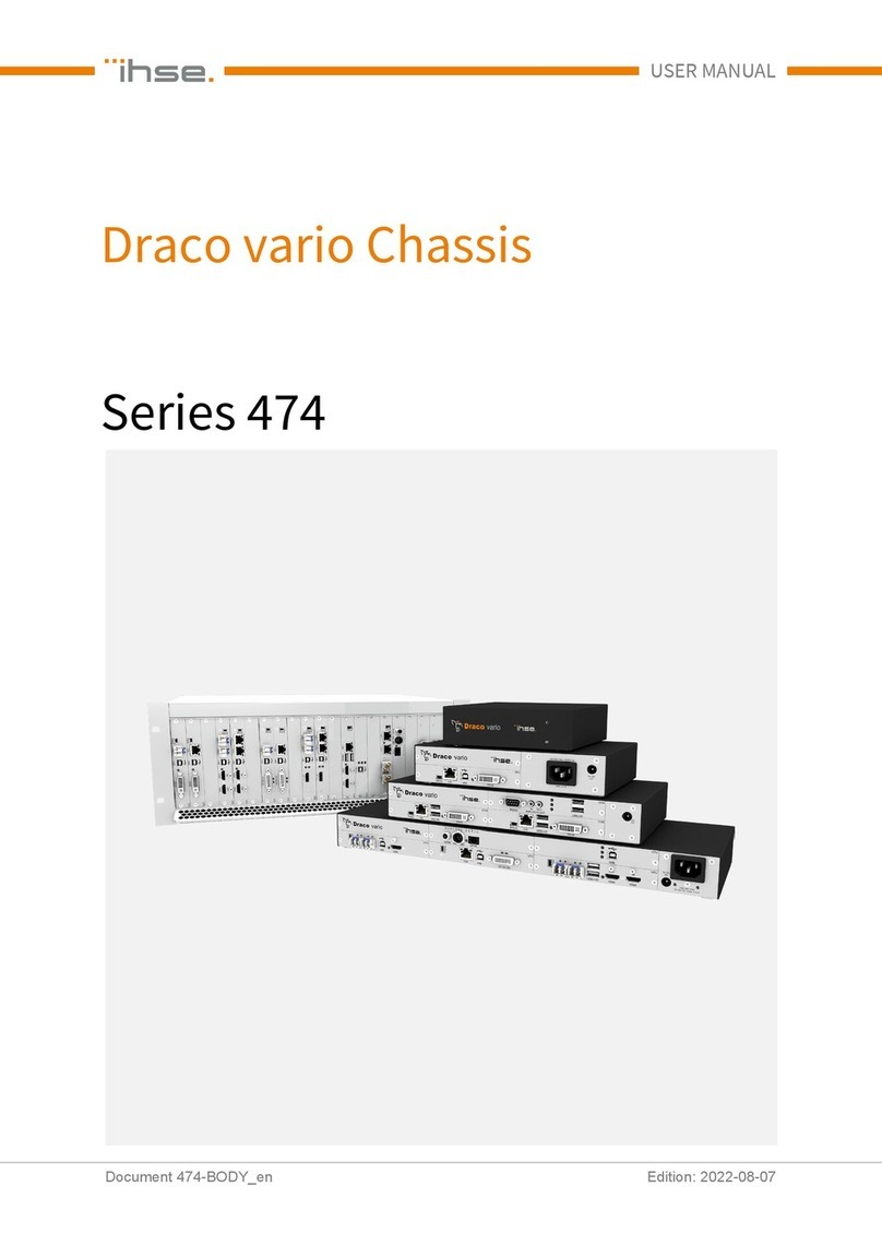
Ihse Draco vario 474 Series User manual

Document 474-BODY_en
Edition: 2022-03-24
USER MANUAL
Draco vario Chassis
Series 474

Introduction
This manual contains important safety instructions as well as instructions for setting up the product and
operating it.
Please read the general safety instructions (see chapter 2, page 6) and additional notice in the
respective chapters. Read carefully through the User Manual be
fore you switch on the product.
Product Identification
The model and serial number of your products are indicated on the bottom of our products. Always refer to
this information when you need to contact your dealer or the support of IHSE GmbH (see chapter 7,
page 38).
Trademarks and Trade Names
All trademark and trade names mentioned in this document are acknowledged to be the property of their
respective owners.
Validity of this Manual
This manual applies to all products of the series named on the cover page. Differences between the various
models are clearly described.
The manufacturer reserves the right to change specifications, functions or circuitry of the series described
here without notice. Information in this manual can be changed, expanded, or deleted without notice. You
can find the current version of the manual in the download area of our website.
Copyright
© 2022. All rights reserved. This manual may not be reproduced in any manner without the prior written
consent of the manufacturer.
Available Documentation
Name Format Description Provision
User Manual PDF Provides an overview of the product together with
technical data and safety instructions.
Contains all instructions required to operate the
product to a basic level.
Download from
website
Quick Setup Print Provides a quick installation guide and safety
instructions
Contained in the
scope of delivery
Contact
IHSE GmbH
Benzstraße 1
88094 Oberteuringen
Germany
phone: +49 7546-9248-0
fax: +49 7546-9248-48
e-mail: info@ihse.com
website: https://www.ihse.com

Chassis 474-BODY Table of Contents
3
Table of Contents
Table of Contents .......................................................................................................................................................... 3
1Important Information .................................................................................................................................... 5
1.1 Symbols for Warnings and Helpful Information...................................................................................... 5
1.2 EU Declaration of Conformity ................................................................................................................ 5
2Safety instructions ......................................................................................................................................... 6
3Consignes de Sécurité................................................................................................................................... 8
4Description....................................................................................................................................................10
4.1 Intended Use.......................................................................................................................................... 5
4.2 System Overview - Numbering of the Chassis Slots ...........................................................................10
4.3 Product Types ......................................................................................................................................11
4.3.1 Mounting Chassis ...................................................................................................................... 11
4.3.2 Slide-in Chassis ......................................................................................................................... 11
4.4 Accessories.......................................................................................................................................... 12
4.4.1 Accessories - Power Supply Voltage......................................................................................... 12
4.4.2 Accessories - Mounting Options ................................................................................................12
4.4.3 Accessories - Fans ....................................................................................................................12
4.5 Scope of Delivery ................................................................................................................................. 13
4.6 Device Views Draco vario Chassis ......................................................................................................14
4.6.1 2-Slot-Chassis Draco vario 474-BODY2....................................................................................14
4.6.2 2-Slot-Chassis Draco vario 474-BODY2R.................................................................................14
4.6.3 2-Slot Chassis Draco vario 474-BODY2N .................................................................................15
4.6.4 2-Slot Chassis Draco vario 474-BODY2DC-12/24/48 ...............................................................15
4.6.5 2-Slot-Chassis Draco vario 474-BODY2BPF/474-BODY2BPF-S .............................................15
4.6.6 2-Slot Chassis Draco vario 474-BODY2BPF-SNMP .................................................................16
4.6.7 4-Slot-Chassis Draco vario 474-BODY4....................................................................................16
4.6.8 4-Slot Chassis Draco vario 474-BODY4R .................................................................................16
4.6.9 6-Slot Chassis Draco vario 474-BODY6R-R1 ...........................................................................17
4.6.10 2-Slot Chassis Draco vario 474-BODY6DC-12/24/48 ...............................................................17
4.6.11 6-Slot Chassis Draco vario 474-BODY6BP/474-BODY6BP-S..................................................18
4.6.12 2-Slot Chassis Draco vario 474-BODY6BP-SNMP ...................................................................18
4.6.13 6-Slot Chassis Draco vario 474-BODY6BPF/474-BODY6BPF-S .............................................19
4.6.14 21-Slot Chassis Draco vario 474-BODY21/4U and 474-BODY21/4UR ....................................19
4.7 Status Indication of the Chassis........................................................................................................... 20
4.7.1 2-Slot-Chassis Draco vario 474-BODY2....................................................................................20
4.7.2 2-Slot-Chassis Draco vario 474-BODY2R.................................................................................20
4.7.3 2-Slot-Chassis Draco vario 474-BODY2N.................................................................................21
4.7.4 2-Slot-Chassis Draco vario 474-BODY2DC-12/24/48 ...............................................................22
4.7.5 2-Slot-Chassis Draco vario 474-BODY2BPF/474-BODY2BPF-S .............................................23
4.7.6 2-Slot-Chassis Draco vario 474-BODY2BPF-SNMP.................................................................24
4.7.7 4-Slot-Chassis Draco vario 474-BODY4....................................................................................25
4.7.8 4-Slot-Chassis Draco vario 474-BODY4R.................................................................................26
4.7.9 6-Slot-Chassis Draco vario 474-BODY6R-R1 ...........................................................................27
4.7.10 6-Slot-Chassis Draco vario 474-BODY6DC-12/24/48 ...............................................................27

Table of Contents Chassis 474-BODY
4
4.7.11 6-Slot Chassis Draco vario 474-BODY6BP/474-BODY6BP-S ..................................................28
4.7.12 2-Slot-Chassis Draco vario 474-BODY6BP-SNMP ...................................................................29
4.7.13 6-Slot-Chassis Draco vario 474-BODY6BPF/474-BODY6BPF-S .............................................31
4.7.14 21-Slot Chassis Draco vario 474-BODY21/4U and 474-BODY21/4UR ....................................32
5Maintenance..................................................................................................................................................33
6Technical Data ..............................................................................................................................................34
6.1 Interface RJ45 (Network) .....................................................................................................................34
6.2 Connector Pinouts................................................................................................................................34
6.2.1 RJ45 (Network) ..........................................................................................................................34
6.2.2 Power Socket - 2.5-mm Barrel...................................................................................................34
6.2.3 Power Socket - C14 ...................................................................................................................34
6.2.4 Power Socket - Kycon................................................................................................................34
6.2.5 Power Socket - PCB Connector.................................................................................................34
6.3 Current Draw, Power Supply Voltage and Power Consumption..........................................................35
6.4 Environmental Conditions and Emissions............................................................................................36
6.5 Dimensions...........................................................................................................................................36
6.6 Weight ..................................................................................................................................................37
6.7 MTBF....................................................................................................................................................37
7Technical Support ........................................................................................................................................38
7.1 Support Checklist .................................................................................................................................38
7.2 Shipping Checklist................................................................................................................................38
8Index ..............................................................................................................................................................39
9Table of Figures............................................................................................................................................40
10 Change Log...................................................................................................................................................41

Chassis 474-BODY Important Information
5
1 Important Information
1.1 Symbols for Warnings and Helpful Information
The meaning of the symbols used for warnings and helpful information in this manual is described below:
NOTICE
NOTICE identifies information, if not observed, endangers the functionality of your device or the security
of your data.
This symbol indicates information about special features on the device or when
using device and function
variants.
This symbol indicates instructions for procedures recommended by the manufacturer for an effective
utilization of the device potential.
1.2 Intended Use
474-BODY chassis are developed and intended to mount or to slide in IHSE KVM extender modules and
add-on modules, or supplementary with extended function. The intended use includes the limitations and
safety instructions according to this user manual. A usage not according to the intended purpose, an
ignorance of this user manual, as well as unauthorized modifications exclude the liability of the
manufacturer of damages resulting from this.
NOTICE
Interferences when the immunity limit values are exceeded
If the limit values listed in EN55024 are exceeded, reliable and fault-free functioning of the devices cannot
be guaranteed.
NOTICE
Radio interference in a domestic environment
This is a Class A product. In a domestic environment, this product may cause radio interference in which
case the user may be required to take adequate measures.
Follow the safety and installation instructions given in this manual.
Use connection cables according to the specifications for the length and type given in this manual.
1.3 EU Declaration of Conformity
Please find the EU Declaration of Conformity for complete devices (extender modules installed in chassis)
under: www.ihse.com/eu-declaration-of-conformity

Safety instructions Chassis 474-BODY
6
2 Safety instructions
To ensure reliable and safe long-term operation of your device, please note the following guidelines:
Read this user manual carefully.
Only use the device according to this user manual. Failure to follow the instructions described can
damage the device or endanger the security of your data.
Take any required ESD precautions.
WARNING
Risk of electric shock due to freely accessible power connections when the chassis is open
Risk of bruising, abrasion or shearing of fingertips due to rotating fan when the chassis is open
If the chassis is opened while power is supplied to the device, electric shock may occur if the internal
wiring is touched. If a running fan is touched while the case is open, bruises, abrasions or shearing of
fingertips may occur.
There are no necessary maintenance procedures that require opening the chassis.
Do NOT remove the cover of the chassis.
Do NOT install the device in environments where children are likely to be present.
CAUTION
Risk of burns due to tremendously heated chassis surface after a long period of operation
When the chassis is fully equipped, the surface of the chassis can become very warm after a long period
of operation. If the chassis surface is touched after a long period of operation, this can cause skin burns.
Protective gloves must be worn to transport a fully equipped chassis after a long period of operation.
Ensure that there is sufficient distance from the operator, e.g., for mounting under a table.
Do NOT install the device in environments where children are likely to be present.
Installation Location
While operating the device and the power supply units can get warm. Damage to the device can occur in a
damp environment.
Use the device only in dry, indoor environments.
Use the device only in a room with adequate ventilation.
For rack-mount installations, at least 0.5 RU (rack unit) is required above the device for ventilation.
Do not place the power supply units directly on top of the device.
Existing ventilation openings on the device must always be free.
If installing the device under the table, place the device at a sufficient distance from the operator.
Place all power sockets including the sockets for the supplied external power supply units easily
accessible and directly next to each other.

Chassis 474-BODY Safety instructions
7
Connection
Check the device and the power supply units for visible damage before connecting it.
Only connect the device if the device and the ports are not damaged.
Only use power supply units originally supplied with the product or manufacturer-approved
replacements.
Only use power supply units without any visible damage at the chassis or the cable.
Connect all power supply units to grounded outlets.
Ensure that the ground connection is maintained from the outlet socket through to the power supply
unit's AC power input.
Only connect the device to KVM devices using the interconnecting cable - not to other devices,
particularly not to telecommunications or network devices.
Disconnect the Device from the Circuit
NOTICE
The cable plugs on the device side can contain a lock. In the event of a necessary quick and complete
disconnection from external electric circuits:
Remove all corresponding cable plugs from the socket,
Or set the power switch of the power outlets (if available) to the “Off” position.

Consignes de Sécurité Chassis 474-BODY
8
3 Consignes de Sécurité
Pour garantir un fonctionnement fiable et sûr de votre périphérique à long terme, veuillez respecter les
directives suivantes :
Lisez attentivement ce manuel d'utilisation.
N'utilisez le périphérique que conformément à ce manuel d'utilisation. Le non-respect des instructions
décrites peut endommager le périphérique ou mettre en danger la sécurité de vos données
Prenez toutes les précautions nécessaires contre les décharges électrostatiques.
AVERTISSEMENT
Risque de choc électrique dues de l'accès libre aux connexions électriques lorsque le châssis est
ouvert
Risque de contusion, d'abrasion ou de cisaillement des bouts des doigts dues de la rotation du
ventilateur lorsque le châssis est ouvert
Si le châssis est ouvert alors que le périphérique est sous tension, un choc électrique peut se produire si
le câblage interne est touché.
Si vous touchez un ventilateur en marche alors que le châssis est ouvert, vous risquez de vous blesser,
de vous abraser ou de vous cisailler le bout des doigts.
Aucune procédure d'entretien nécessaire ne requiert l'ouverture du châssis.
Ne retirez PAS le couvercle du châssis.
N'installez PAS le périphérique dans des environnements où des enfants sont susceptibles d'être
présents.
ATTENTION
Risque de brûlures dues à la surface du châssis très chaude après une longue période
d'utilisation
Lorsque le châssis est entièrement équipé, la surface du châssis peut devenir très chaude après une
longue période de fonctionnement.
Si la surface du châssis est touchée après une longue période d'utilisation, cela peut provoquer des
brûlures de la peau.
Des gants de protection doivent être portés pour transporter un châssis entièrement équipé après une
longue période d'opération.
Veillez à ce que la distance avec l'opérateur soit suffisante, par exemple pour un montage sous une
table.
N'installez PAS le périphérique dans des environnements où des enfants sont susceptibles d'être
présents.
Emplacement de l'installation
Pendant le fonctionnement, le périphérique et les unités d'alimentation peuvent chauffer. Le périphérique
peut être endommagé dans un environnement humide.
N'utilisez le périphérique que dans un environnement sec et intérieur.
N'utilisez le périphérique dans un lieu correctement ventilée.
Pour les installations en rack, au moins 0,5 RU (unité de rack) est nécessaire au-dessus du
périphérique pour la ventilation.
Ne placez jamais les unités d'alimentation sur le dessus du périphérique.
Les ouvertures de ventilation existantes sur le périphérique doivent toujours être libres.
Si vous installez le périphérique sous la table, placez le périphérique à une distance suffisante de
l'opérateur.

Chassis 474-BODY Consignes de Sécurité
9
Placez toutes les prises de courant, y compris les prises de courant pour les unités d'alimentation
externes fournis, de manière facilement accessible et directement les unes à côté des autres.
Connexion
Avant de connecter le périphérique et les unités d'alimentation, vérifiez qu'ils ne présentent pas de
dommages visibles.
Seulement connectez le périphérique et les unités d'alimentation que si le périphérique et les ports ne
sont pas endommagés.
Utilisez uniquement les unités d'alimentation fournis à l'origine avec le produit ou des pièces de
rechange approuvées par le fabricant.
N'utilisez que des unités d'alimentation sans dommages visibles au niveau du châssis ou du câble.
Connectez tous les unités d'alimentation à des prises de terre.
Raccordez tous les unités d'alimentation à des prises de courant mises à la terre.
Veillez à ce que la connexion à la terre soit maintenue depuis la prise de courant jusqu'à l'entrée
d'alimentation CA du les unités d'alimentation.
Ne connectez le périphérique qu'à des périphériques KVM à l'aide du câble d'interconnexion - pas à
d'autres périphériques, en particulier pas à des périphériques de télécommunications ou de réseau.
Déconnecter le périphérique du circuit
AVIS
Les fiches de câble du côté du périphérique peuvent contenir un verrou. En cas de nécessité d'une
déconnexion rapide et complète des circuits électriques externes :
Retirez toutes les fiches de câble correspondantes de la prise.
Ou mettez l'interrupteur des prises de courant (si elles existent) sur la position « Off ».

Description Chassis 474-BODY
10
4 Description
4.1 System Overview - Numbering of the Chassis Slots
The numbering of the slots in the chassis runs from bottom left to top right (2-/4-/6-slot chassis) and from
left to right (21-slot chassis). The slot numbering is relevant for the placement of an SNMP module in a
backplane chassis (see example) or a USB 2.0 stand-alone module in chassis without backplane (slot 2).
2 4 6
1 3 5
Fig. 1
Example 1 - Numbering of the 6-slot chassis with placement (gray) of an SNMP module
1 2 3 4 5 6 7 8 9 10 11 12 13 14 15 16 17 18 19 20 21
Fig. 2
Example 2 - Numbering of the 21-slot chassis with placement (gray) of an SNMP module
In SNMP chassis, the usage of an SNMP board is not possible (see chapter
4.3.2, page 11).

Chassis 474-BODY Description
11
4.2 Product Types
4.2.1 Mounting Chassis
Chassis Power supply unit
Type Slots
Active
backplane Current input Internal External
Setup for redundant
power supply voltage
474-BODY2 2 No Interface side - 1x -
474-BODY2R 2 No Interface side - 1x 1x (external)
474-BODY2N 2 No Interface side 1x - 1x (external)
474-BODY2DC-12
474-BODY2DC-24
474-BODY2DC-48
2 No Interface side 1x - 1x (external)
474-BODY4 4 No Interface side - 1x -
474-BODY4R 4 No Interface side - 1x 1x (external)
474-BODY6R-R1 6 No Interface side 1x - 1x (external)
474-BODY6DC-12
474-BODY6DC-24
474-BODY6DC-48
6 No Interface side 1x - 1x (external)
4.2.2 Slide-in Chassis
Chassis Power supply unit
Type Slots
Active
backplane Current input Internal External
Setup for redundant
power supply voltage
474-BODY2BPF
474-BODY2BPF-S**
474-BODY2BPF-SNMP*
2 Yes Interface side 1x - 1x (external)
474-BODY6BP
474-BODY6BP-S**
474-BODY6BP-SNMP*
6 Yes Rear view 2x - -
474-BODY6BPF
474-BODY6BPF-S** 6 Yes Interface side 2x - -
474-BODY21/4U 21 Yes Rear view 1x - 1x (internal)
474-BODY21/4UR 21 Yes Rear view 2x - -
* The 474-BODY2BPF-SNMP and 474-BODY6BP-SNMP chassis provide SNMP functionality through the
backplane, allowing the chassis to be fully equipped. In SNMP-BODYs, the usage of an SNMP board is
not possible.
** The 474-BODY2BPF-S, 474-BODY6BP-S, and 474-BODY6BPF-S chassis include a quieter fan.
All external power supply units are separately certified to the relevant major international safety standards.

Description Chassis 474-BODY
12
4.3 Accessories
4.3.1 Accessories - Power Supply Voltage
Part. No. Description
474-PSU2 Spare ext. PSU for 2-slot chassis
474-PSU2BPF Spare ext. PSU for 474-BODY2-BPF, lockable connector
474-PSU4 Spare ext. PSU for 474-BODY2N and 474-BODY4/4R
474-PSU6 Spare ext. PSU for 474-BODY6R-R1
474-PSU21 Spare PSU for 474-BODY21/4U, slide-in, hot-swap
260-5G International power supply unit 100...240VAC/5VDC/3A
260-5M International power supply unit 100...240VAC/5VDC/5A
PC-TYP-E/C13-020 Power cord IEC Schuko 90° Type-E/C13 2.0 m lockable
PC-TYP-B/C13-020 Power cord IEC US Type-B/C13 2.0 m lockable
All external power supplies are separately certified according to all relevant safety standards.
4.3.2 Accessories - Mounting Options
Part. No. Description
474-2RMK 19"-Rackmount Ears for Draco vario 2-Slot chassis
474-2NRMK 19"-Rackmount Ears for Draco vario 2-slot chassis w/ built-in PSU
474-4RMK 19"-Rackmount Ears for Draco vario 4-Slot chassis
474-6RMK 19"-Rackmount Ears for Draco vario 6-slot chassis
474-VPLATE Mounting plate for 2-/4-/6-slot chassis
474-VSNAP Mounting plate w/ DIN Rail Snap On for 2-slot chassis
474-BRACKET Wall-/Tablemount L-Brackets for all 2-/4-/6-Slot chassis
474-BLND1 Blanking plate with IHSE Logo, 1-slot for Draco vario chassis
4.3.3 Accessories - Fans
Part. No. Description
474-6FAN Optional fan for Draco vario 2-slot and 6-slot chassis with backplane
474-MODFAN Fan cartridge module, retrofittable for all Draco vario chassis

Chassis 474-BODY Description
13
4.4 Scope of Delivery
Product type Scope of delivery
Per each Draco vario
chassis
474-BODY2
474-BODY2R
•1x 5 V DC/3 A international power supply unit
•1x country-specific power cord
474-BODY4
474-BODY4R
•1x 5 V DC/5 A international power supply unit
•1x country-specific power cord
474-BODY2N
474-BODY2BPF
474-BODY2BPF-S
474-BODY2BPF-SNMP
474-BODY6R-R1
•1x IEC country-specific power cord C13, 2.0 m
474-BODY6BP
474-BODY6BP-S
474-BODY6BP-SNMP
474-BODY6BPF
474-BODY6BPF-S
474-BODY21/4UR
•2x IEC country-specific power cord C13, 2.0 m
lockable
474-BODY21/4U •1x IEC country-specific power cord C13, 2.0 m
lockable
If anything is missing, please contact your distributor.

Description Chassis 474-BODY
14
4.5 Device Views Draco vario Chassis
NOTICE
Exceeding the maximum permissible power consumption
In addition to the power consumption of the used modules, the power consumption of the connected
peripherals must be added.
Note the maximum current draw of the chassis (see chapter 6.3, page 35).
4.5.1 2-Slot-Chassis Draco vario 474-BODY2
Fig. 3 Interface side chassis 474-BODY2
1 Slot 1
2
Slot 2
3 Power supply voltage, DC
4.5.2 2-Slot-Chassis Draco vario 474-BODY2R
Fig. 4 Interface side chassis 474-BODY2R
1 Slot 1
2
Slot 2
3 Power supply voltage 1, DC
4
Power supply voltage 2, DC

Chassis 474-BODY Description
15
4.5.3 2-Slot Chassis Draco vario 474-BODY2N
Fig. 5 Interface side chassis 474-BODY2N
1 Slot 1
2
Slot 2
3 Power supply voltage 1, AC
4
Power supply voltage 2, DC
NOTICE
Excessive current draw
The 2-slot Draco vario chassis with an internal power supply unit is not equipped with a fuse on its
primary side.
The protection against excessive current draw has to be provided by the electrical installation of the
building.
4.5.4 2-Slot Chassis Draco vario 474-BODY2DC-12/24/48
Fig. 6 Interface side chassis 474-BODY2DC-12/24/48
1 Slot 1
2
Slot 2
3 Power supply voltage 1, DC
4
Power supply voltage 2, DC
4.5.5 2-Slot-Chassis Draco vario 474-BODY2BPF/474-BODY2BPF-S
New chassis version, available on demand
Fig. 7 Interface side chassis 474-BODY2BPF/474-BODY2BPF-S
1 Slot 1
2
Slot 2
3 Power supply voltage 2, DC
4
Power supply voltage 1, AC

Description Chassis 474-BODY
16
4.5.6 2-Slot Chassis Draco vario 474-BODY2BPF-SNMP
Fig. 8 Interface side chassis 474-BODY2BPF-SNMP
1 Slot 1
2
Slot 2
3
Power supply voltage 2, DC
4 Network
5
Power supply voltage 1, AC
4.5.7 4-Slot-Chassis Draco vario 474-BODY4
Fig. 9 Interface side chassis 474-BODY4
1 Slot 1
2
Slot 2
3
Slot 3
4 Slot 4
5
Power supply voltage, DC
4.5.8 4-Slot Chassis Draco vario 474-BODY4R
Fig. 10 Interface side chassis 474-BODY4R
1 Slot 1
2
Slot 2
3
Slot 3
4 Slot 4
5
Power supply voltage 2, DC
6
Power supply voltage 1, DC

Chassis 474-BODY Description
17
4.5.9 6-Slot Chassis Draco vario 474-BODY6R-R1
Fig. 11 Interface side chassis 474-BODY6R-R1
1 Slot 1
2
Slot 2
3
Slot 3
4
Slot 4
5 Slot 5
6
Slot 6
7
Power supply voltage 2, DC
8
Power supply voltage 1, AC
NOTICE
Too low power supply voltage
With Draco vario chassis 474-BODY6R-R1 a redundant power supply voltage is possible up to a current
of maximum 5 A (modules inclusive connected periphery). If the power supply voltage of the internal
power supply unit fails, the device's power supply voltage is secured via the 5 V external power supply
unit.
If there is no redundant power supply voltage and the current is above 5 A, the device is not supplied with
sufficient power supply voltage and fails.
Note the maximum current draw of the chassis (see chapter 6.3, page 35).
With a current of more than 5 A, use an external power supply unit. In this case, redundancy is
inapplicable.
NOTICE
Excessive current draw
The 6-slot Draco vario chassis with an internal power supply unit is not equipped with a fuse on its
primary side.
The protection against excessive current draw has to be provided by the electrical installation of the
building.
4.5.10 2-Slot Chassis Draco vario 474-BODY6DC-12/24/48
Fig. 12 Interface side chassis 474-BODY6DC-12/24/48
1 Slot 1
2
Slot 2
3
Slot 3
4
Slot 4
5 Slot 5
6
Slot 6
7
Power supply voltage 1, DC
8
Power supply voltage 2, DC

Description Chassis 474-BODY
18
4.5.11 6-Slot Chassis Draco vario 474-BODY6BP/474-BODY6BP-S
Fig. 13 Interface side chassis 474-BODY6BP/474-BODY6BP-S
1 Slot 1
2
Slot 2
3
Slot 3
4 Slot 4
5
Slot 5
6
Slot 6
Fig. 14 Rear view chassis 474-BODY6BP/474-BODY6BP-S
1 Power supply voltage 1, AC
2
Power supply voltage 2, AC
3 Grounding
4.5.12 2-Slot Chassis Draco vario 474-BODY6BP-SNMP
Fig. 15 Interface side chassis 474-BODY6BP-SNMP
1 Slot 1
2
Slot 2
3
Slot 3
4
Slot 4
5 Slot 5
6
Slot 6
7
Network
Fig. 16 Rear view chassis 474-BODY6BP-SNMP
1 Power supply voltage 1, AC
2
Power supply voltage 2, AC
3 Grounding

Chassis 474-BODY Description
19
4.5.13 6-Slot Chassis Draco vario 474-BODY6BPF/474-BODY6BPF-S
Fig. 17 Interface side chassis 474-BODY6BPF/474-BODY6BPF-S
1 Slot 1
2
Slot 2
3
Slot 3
4
Slot 4
5 Slot 5
6
Slot 6
7
Power supply voltage 1, AC
8
Power supply voltage 2, AC
4.5.14 21-Slot Chassis Draco vario 474-BODY21/4U and 474-BODY21/4UR
Fig. 18 Interface side chassis 474-BODY21/4U and 474-BODY21/4UR
1 Slots 1 to 21 (from left to right)
The chassis 474
-BODY21/4U is supplied with one power supply unit (Pos. 3). A second power supply unit
can be optionally installed.
The chassis 474
-BODY21/4UR is supplied with two power supply units (Pos. 2 and 3).
Fig. 19 Rear view chassis 474-BODY21/4U and 474-BODY21/4UR
1 Power supply voltage 2, AC (redundancy)
2
Power supply unit 2 (redundancy)
3 Power supply unit 1
4
Power supply voltage 1, AC

Description Chassis 474-BODY
20
4.6 Status Indication of the Chassis
For an easier identification, the LED representation and column designation in the tables were selected
analogously to the LED position on the chassis.
4.6.1 2-Slot-Chassis Draco vario 474-BODY2
Fig. 20 Interface side chassis 474-BODY2 - LED for power supply voltage
1 LED for power supply voltage
LED for Power Supply Voltage
The following table shows the LED states/colors for the power supply voltage (see chapter 4.6.1, page 14)
for the respective situation.
LED Status Description
Green
Redundant power supply voltage available.
Off No power supply voltage available.
4.6.2 2-Slot-Chassis Draco vario 474-BODY2R
Fig. 21 Interface side chassis 474-BODY2R - LEDs for power supply voltage
1 LED for power supply voltage 1
2 LED for power supply voltage 2
LEDs for Power Supply Voltage
The following tables show the LED states/colors for the power supply voltage (see chapter 4.6.2, page 14)
for the respective situation.
Pos. LED Status Description
2
Green
Redundant power supply voltage available.
1
Green
2
Green
No redundant power supply voltage available.
1
Red
2
Red
No redundant power supply voltage available.
1
Green
2
Off
No power supply voltage available.
1 Off
Other manuals for Draco vario 474 Series
1
This manual suits for next models
22
Table of contents
Other Ihse Chassis manuals
