Ihse 485 Series User manual
IHSE GmbH
Maybachstrasse 11
88094 Oberteuringen
Germany
www.ihse.de
Tel. +49 7546-9248-0
Fax +49 7546-9248-48
User Manual
Edition: 2014-04-15
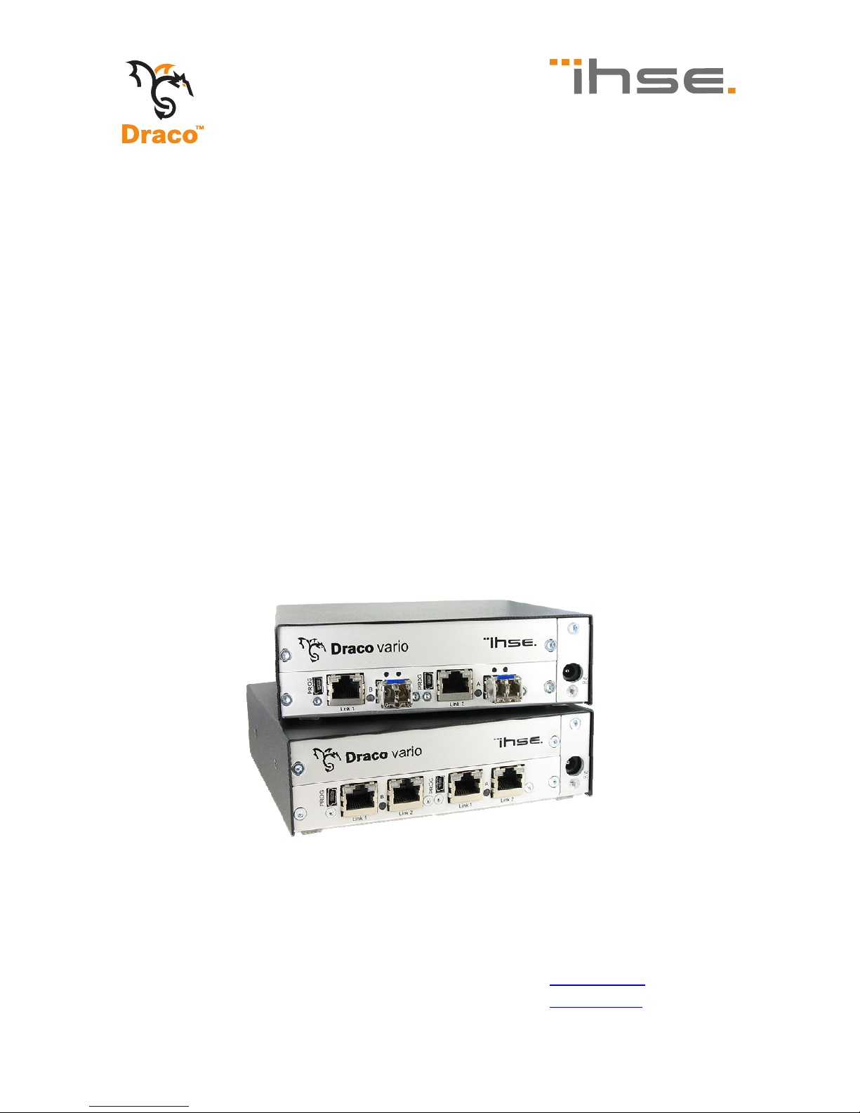
Draco
(Cross) Repeater
Model:
485 Series

Draco (Cross) Repeater
2 2014-04-15
Copyright
© 2014. All rights reserved. This information may not be reproduced in any
manner without the prior written consent of the manufacturer.
Information in this document is subject to change without notice.
Trademarks
All trademark and trade names mentioned in this document are
acknowledged to be the property of their respective owners.
Disclaimer
While every precaution has been taken during preparation of this manual,
the manufacturer assumes no liability for errors or omissions. The
manufacturer assumes no liability for damages resulting from the use of
the information contained herein.
The manufacturer reserves the right to change specifications, functions, or
circuitry of the product without notice.
The manufacturer cannot accept liability for damage due to misuse of the
product or due to any other circumstances outside the manufacturer’s
control (whether environmental or installation related). The manufacturer
shall not be liable for any loss, damage, or injury arising directly, indirectly,
incidentally, or consequently from the use of this product.

Contents
2014-04-15 3
Contents
1 About This Manual ....................................................................... 5
1.1 Scope.................................................................................. 5
1.2 Validity ................................................................................ 5
1.3 Cautions and Notes ............................................................ 5
2 Safety Instructions....................................................................... 6
3 Description ................................................................................... 7
3.1 Application .......................................................................... 7
3.2 System Overview ................................................................ 8
3.3 Product Range .................................................................... 9
3.3.1 Chassis ................................................................. 9
3.3.2 (Cross) Repeater Modules.................................. 10
3.4 Accessories Upgrade Kits................................................. 10
3.5 Accessories....................................................................... 11
3.6 Device Views .................................................................... 11
3.6.1 2-fold Vario Chassis 474-BODY2/2R .................. 11
3.6.2 2-fold Vario Chassis 474-BODY2N ..................... 12
3.6.3 4-fold Vario Chassis 474-BODY4/4R .................. 13
3.6.4 6-fold Vario Chassis 474-BODY6R ..................... 14
3.6.5 6-fold Vario Chassis 474-BODY6BP................... 15
3.6.6 6-fold Vario Chassis 474-BODY6BPF................. 16
3.6.7 21-fold Vario Chassis 474-BODY21R ................. 17
3.6.8 Model 485-BC ..................................................... 18
3.6.9 Model 485-BS ..................................................... 18
3.6.10 Model 485-BX ..................................................... 18
3.6.11 Model 485-BCC .................................................. 19
3.6.12 Model 485-BSS................................................... 19
3.6.13 Model 485-BXX................................................... 20
3.7 Status LEDs ...................................................................... 21
3.7.1 Status (Cross) Repeater Module......................... 21

Draco (Cross) Repeater
4 2014-04-15
4 Installation .................................................................................. 22
4.1 Package Contents............................................................. 22
4.2 System anschließen.......................................................... 22
4.2.1 (Cross) Repeater Setup ...................................... 22
4.3 Example Applications........................................................ 23
5 Configuration.............................................................................. 25
6 Operation .................................................................................... 25
7 Specifications............................................................................. 26
7.1 Interfaces .......................................................................... 26
7.1.1 RJ45 (Interconnect) ............................................ 26
7.1.2 Fiber SFP Type LC (Interconnect) ...................... 26
7.2 Interconnect Cable............................................................ 27
7.2.1 Cat X................................................................... 27
7.2.2 Fiber.................................................................... 28
7.3 Connector Pinouts ............................................................ 29
7.4 Power Supply.................................................................... 30
7.5 Environmental Conditions ................................................. 30
7.6 Size................................................................................... 31
7.7 Shipping Weight................................................................ 32
8 Troubleshooting......................................................................... 33
8.1 General Failures ............................................................... 33
9 Technical Support ...................................................................... 34
9.1 Support Checklist.............................................................. 34
9.2 Shipping Checklist ............................................................ 34
10 Certificates.................................................................................. 35
10.1 CE Declaration Of Conformity........................................... 35
10.2 North American Regulatory Compliance........................... 36
10.3 Product Safety .................................................................. 36
10.4 WEEE ............................................................................... 37
10.5 RoHS/RoHS 2................................................................... 37
11 Glossary...................................................................................... 38
Pos: 1 /806-IHSE/ Zu diesem Handbuch/A TB_Zu diesem Handbuch @ 5\mod_1278 573163276_6.doc @ 41510 @ 1222 @ 1

About This Manual
2014-04-15 5
1 About This Manual
1.1 Scope
This manual describes how to install your (Cross) Repeater, how to
operate it and how to perform trouble shooting.
1.2 Validity
This manual is valid for all devices listed on the front page. The product
code is printed on the base of the devices.
1.3 Cautions and Notes
The following symbols are used in this manual:
This symbol indicates an important operating instruction that should be
followed to avoid any potential damage to hardware or property, loss of
data, or personal injury.
This symbol indicates important information to help you make the best use
of this product.
This symbol indicates best practice information to show recommended
and optimal ways to use this product in an efficient way.
Pos: 2 /806-IHSE/ Sicherheitshinweis e/ATB_Sicherheits hinweise @ 5\mod_12785 73321245_6.doc @ 41528 @ 1 @ 1

Draco (Cross) Repeater
6 2014-04-15
2 Safety Instructions
To ensure reliable and safe long-term operation of your (Cross) Repeater
please note the following guidelines:
Installation
Only use in dry, indoor environments.
The (Cross) Repeater and the power supply units can get warm. Do
not install components in an enclosed space without any airflow.
Do not place the power supply directly on top of the device.
Do not obscure ventilation holes.
Only use power supplies originally supplied with the product or
manufacturer-approved replacements. Do not use a power supply if it
appears to be defective or has a damaged chassis.
Connect all power supplies to grounded outlets. In each case, ensure
that the ground connection is maintained from the outlet socket
through to the power supply's AC power input.
Do not connect the link interface to any other equipment, particularly
network or telecommunications equipment.
Take any required ESD precautions.
In order to disconnect the device completely from the electric circuit, all
power cables have to be removed.
Repair
Do not attempt to open or repair a power supply unit.
Do not attempt to open or repair the (Cross) Repeater. There are no
user serviceable parts inside.
Please contact your dealer or manufacturer if there is a fault.
Pos: 3 /806-IHSE/ Beschreibung/UEB_Besc hreibung @ 5\mod_1278 573379151_6.doc @ 41546 @ 1 @ 1

Description
2014-04-15 7
3 Description
Pos: 4 /806-IHSE/ Beschreibung/Ver wendungszweck/485- xx@ 1 1\mod_1395145109102 _6.doc @ 140748 @ 2 @ 1
3.1 Application
The (Cross) Repeater is basically used in order to double the maximum
cabling distance between a KVM extender CON or CPU Unit or even a
KVM matrix. In addition to that the device can also be used for media
conversion from Cat X to fiber or vice versa.
The device is available as a pure Cat X or fiber version (repeater) and as
a hybrid version of Cat X and fiber (cross repeater) for an additional
electrical/optical signal conversion.
Pos: 5 /806-IHSE/ Beschreibung/Syst em-Übersicht /485- xx@ 11\ mod_1395145337503 _6.doc @ 140779 @ 2 @ 1

Draco (Cross) Repeater
8 2014-04-15
3.2 System Overview
The (Cross) Repeater consists of at least one module depending on the
application.
The device is connected between a KVM extender CON and CPU Unit via
the interconnect cable or can be alternatively connected between a KVM
extender unit and a KVM matrix.
The (Cross) Repeater communicates with both the KVM extenders and a
KVM-Matrix via the interconnect cables.
1 2 4 53 761 2 4 53 76
System Overview
1 Source (computer, CPU)
2 KVM Extender CPU Unit
3 Interconnect cable (Cat X or fiber)
4 (Cross) Repeater
5 Interconnect cable (Cat X or fiber)
6 KVM Extender CON Unit
7 Console (monitor, keyboard, mouse)
See Chapter 4.3, Page 23 for installation examples.
Pos: 6 /806-IHSE/ Beschreibung/Gerä tetypen/485-xx @ 11\ mod_1395145641436_6.d oc @ 140805 @ 233 @ 1

Description
2014-04-15 9
3.3 Product Range
3.3.1 Chassis
Model Description
474-BODY2 Empty chassis for up to 2 boards, 1x external power
supply unit
474-BODY2R Empty chassis for up to 2 boards, 1x external power
supply unit, preparation for redundancy for a second
power supply unit (external)
474-BODY2N Empty chassis for up to 2 boards, 1x internal power
supply unit, preparation for redundancy for a second
power supply unit (external)
474-BODY4 Empty chassis for up to 4 boards, 1x external power
supply unit
474-BODY4R Empty chassis for up to 4 boards, 1x external power
supply unit, preparation for redundancy for a second
power supply unit (external)
474-BODY6R Empty chassis for up to 6 boards, 1x internal power
supply unit, preparation for redundancy for a second
power supply unit (external)
474-
BODY6BP
Empty chassis for up to 6 boards, active backplane, 2x
internal power supply unit (redundancy)
474-
BODY6BPF
Empty chassis for up to 6 boards, active backplane, 2x
internal power supply unit (redundancy) with connectors
on rear side
474-
BODY21/4U
Empty chassis for up to 21 boards, 1x internal power
supply unit, preparation for redundancy for a second
power supply unit (internal)
Draco (Cross) Repeater
10 2014-04-15
3.3.2 (Cross) Repeater Modules
Model Description
485-BC Repeater module Cat X for range extension up to 280 m
485-BS Repeater module fiber (Single-Mode) for range
extension up to 20,000 m
485-BX Repeater module Cat X/fiber (Single-Mode) for an
electrical/optical media conversion, maximum extension
10,140 m
485-BCC Dual repeater module Cat X for range extension up to
280 m
485-BSS Dual repeater module fiber (Single-Mode) for range
extension up to 20,000 m
485-BXX Repeater module Cat X/fiber (Single-Mode) for an
electrical/optical media conversion, maximum extension
10,140 m
Pos: 7 /806-IHSE/ Beschreibung/Einb auoptionen/474- xx@ 6\m od_1304580008551_6.doc @ 50839 @ 2 @ 1
3.4 Accessories Upgrade Kits
Model Description
474-2RMK 19"/1U rack mount kit for 2-fold chassis
474-
2NRMK
19"/1U rack mount kit for 2-fold chassis with internal PSU
474-4RMK 19"/1U rack mount kit for 4-fold chassis
474-6RMK 19"/1U rack mount kit for 6-fold chassis
474-
VPLATE
Fastening strips for screw or snap on for 2-, 4- and 6-fold
chassis
474-
OPTRED
Retrofitting for redundant power supply option (without
power supply) for 2- and 4-fold chassis
474-PSU2 Power supply for 2-fold chassis (spare or redundancy)
474-PSU4 Power supply for 4-fold chassis (spare or redundancy)
474-PSU6 Power supply for 6-fold chassis (spare or redundancy)
474-PSU21 Power supply for 6-fold-chassis (spare or redundancy)
474-BLND1 Blind plate 3U/4HP for 2-, 4- and 6-fold chassis
474-BLND2 Blind plate 3U/8HP for 2-, 4- and 6-fold chassis

Description
2014-04-15 11
(Cross) Repeaters and the power supply units can get warm and must not
be installed in closed rooms with no air circulation. For rack-mount
installations, at least 0.5 U (height unit) is required above the (Cross)
Repeater for ventilation.
Pos: 8 /806-IHSE/ Beschreibung/Zubehör /485-xx @ 11\mod_139514 5995119_6.doc @ 140842 @ 2 @ 1
3.5 Accessories
Model Description
260-5G International power supply unit 100...240 VAC / 5 VDC / 3 A
260-5U International power supply unit 100...240 VAC / 5 VDC / 4 A
474-
PSULOCK
IEC connection cable for power supply, lockable
Pos: 9 /806-IHSE/ Beschreibung/Gerä teansichten/UEB_Ger äteansichten @ 5\mod_127 8573737808_6.doc @ 41654 @ 2 @ 1
3.6 Device Views
Pos: 10 /806-IHSE/ Beschreibung/Gerä teansichten/474- xx/2-fach Vario- Gehäuse 474-BODY2/2R @ 6\mod_1 304580280566_6.doc @ 50858 @ 3 @ 1
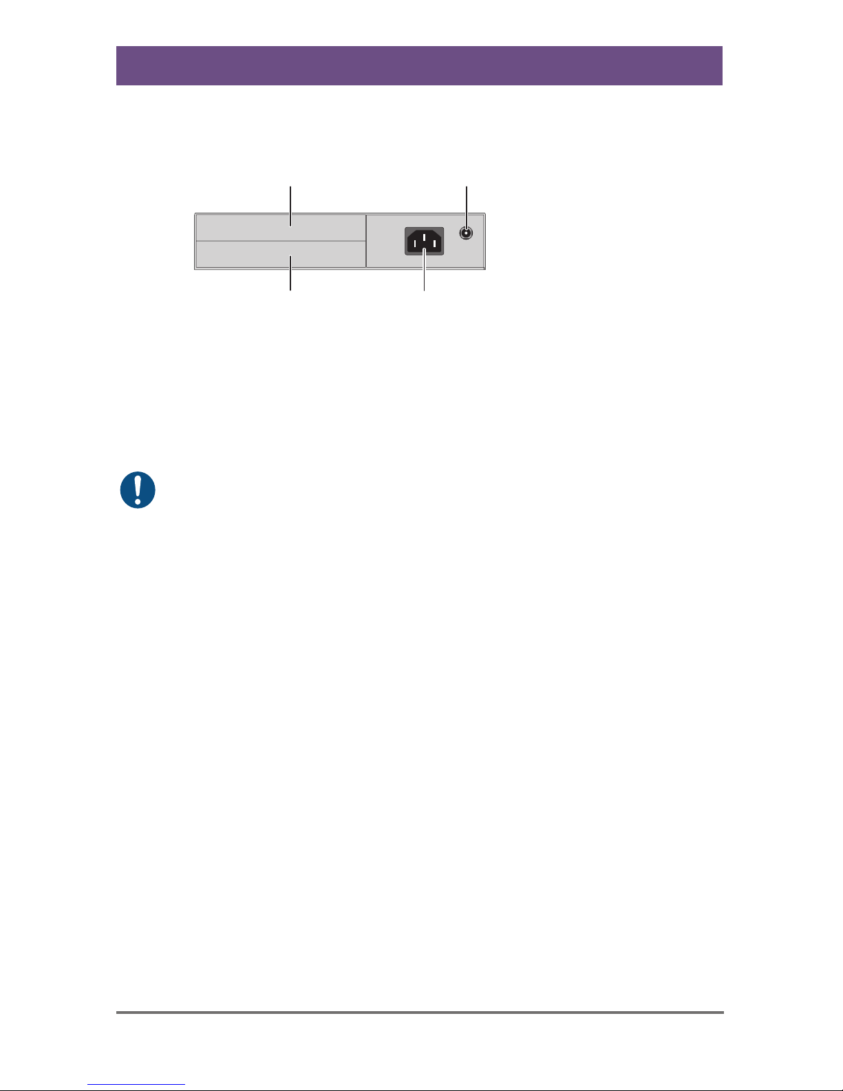
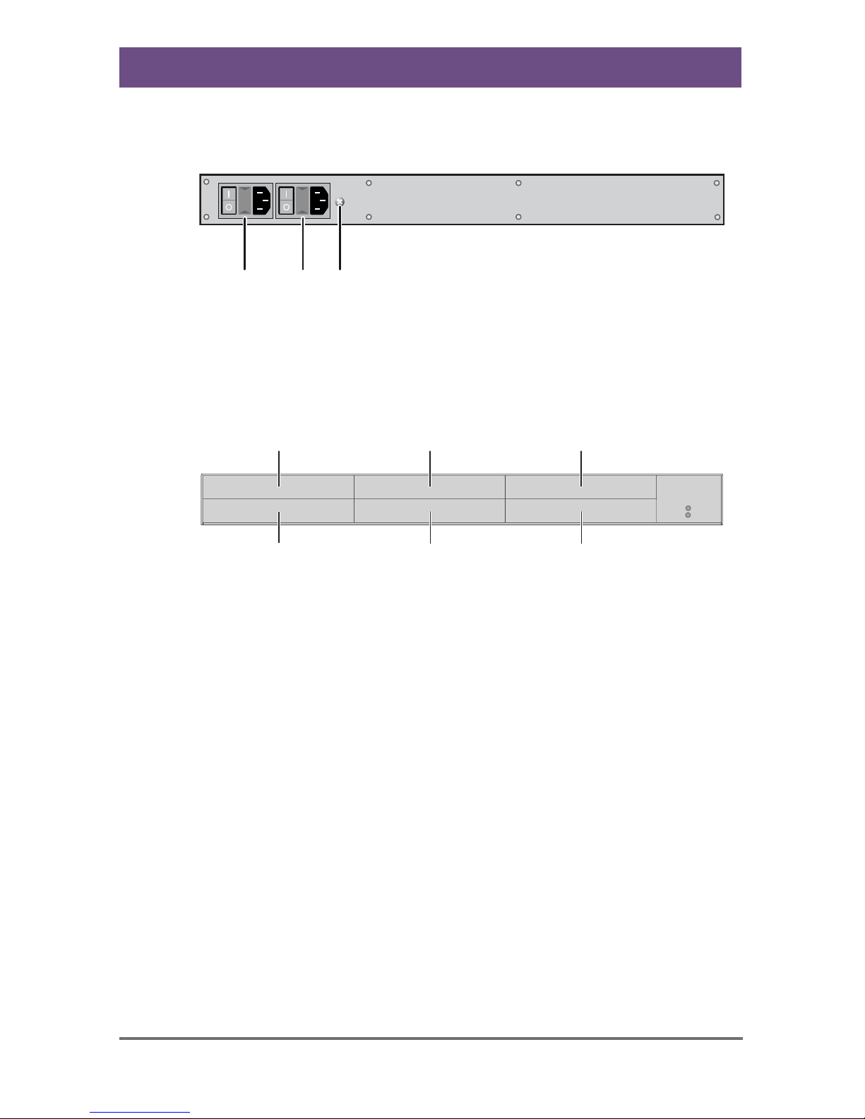
3.6.1 2-fold Vario Chassis 474-BODY2/2R
CPU and CON Unit
1
2
34
Rear View
1 Slot for modules #1
2 Connect to 5VDC power supply (standard)
3 Slot for modules #2
4 Connect to 5VDC power supply (redundancy, optional)
Pos: 11 /806-IHSE/ Beschreibung/Gerä teansichten/474- xx/2-fach Vario- Gehäuse 474-BODY2N @ 8\mod_13485 78478411_6.doc @ 6938 0 @ 3 @ 1
Draco (Cross) Repeater
12 2014-04-15
3.6.2 2-fold Vario Chassis 474-BODY2N
CPU and CON Unit
1
2
34
Rear View
1 Slot for modules #1
2 Connect to power supply (standard)
3 Slot for modules #2
4 Connect to 5VDC power supply (redundancy)
The 2-fold vario chassis with an internal power supply is not equipped with
a fuse on its primary side. Therefore the protection against excessive
currents has to be provided by the electrical installation of the building.
Pos: 12 /806-IHSE/ Beschreibung/Gerä teansichten/474- xx/4-fach Vario- Gehäuse 474-BODY4/4R @ 6\mod_1 304580359098_6.doc @ 50876 @ 3 @ 1

Description
2014-04-15 13
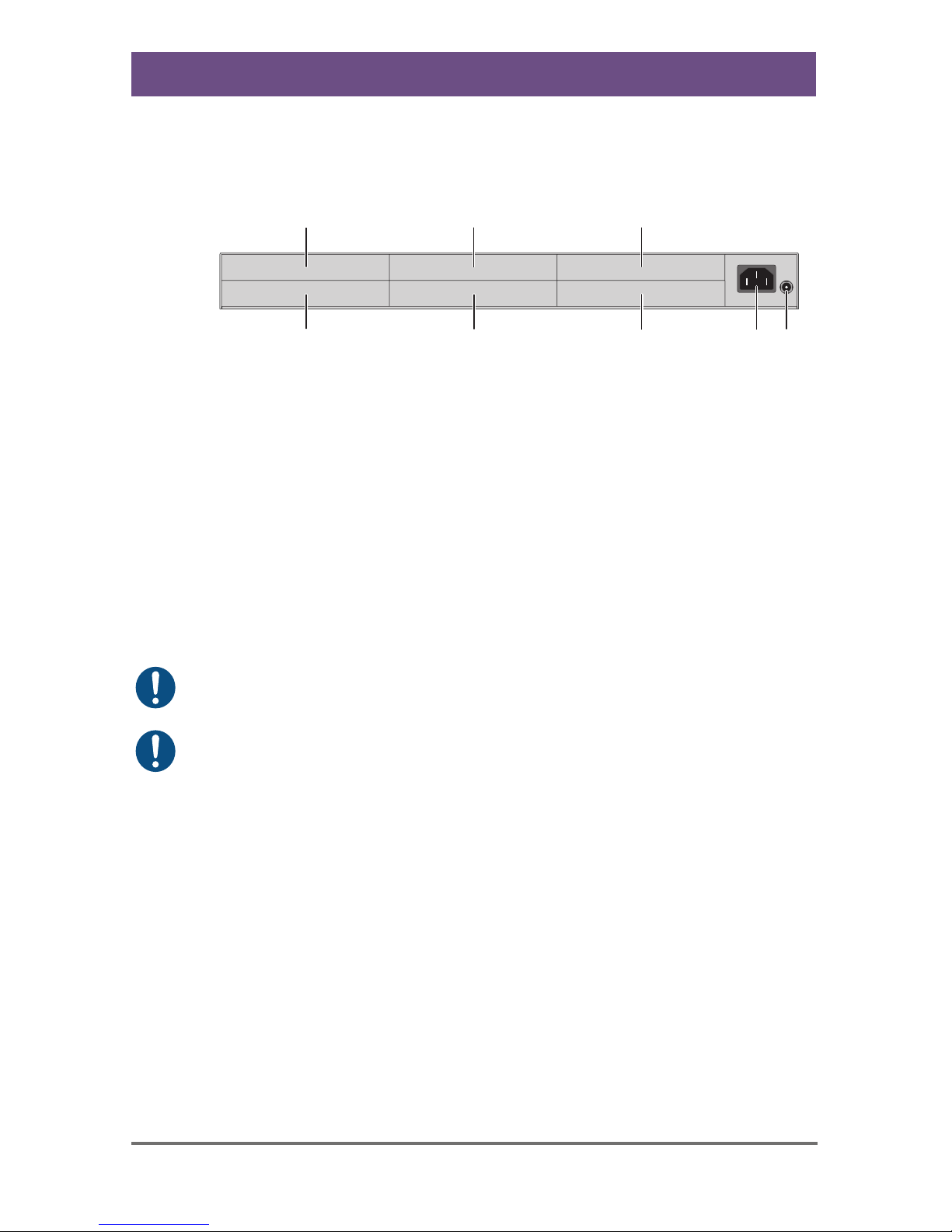
3.6.3 4-fold Vario Chassis 474-BODY4/4R
CPU and CON Unit
3
45
1
2
6
Rear View
1 Slot for modules #3
2 Slot for modules #1
3 Connect to 5VDC power supply (standard)
4 Slot for modules #4
5 Slot for modules #2
6 Connect to 5VDC power supply (redundancy, optional)
For operation with three KVM Extender CON modules and a USB 2.0
CON module in a 4-fold vario chassis, two power supplies are necessary.
In this case, redundancy is inapplicable.
Pos: 13 /806-IHSE/ Beschreibung/Gerä teansichten/474- xx/6-fach Vario- Gehäuse 474-BODY6R @ 6\mod_13045 80442488_6.doc @ 5089 4 @ 3 @ 1
Draco (Cross) Repeater
14 2014-04-15
3.6.4 6-fold Vario Chassis 474-BODY6R
CPU and CON Unit
345
1
2
68
7
Rear View
1 Slot for modules #5
2 Slot for modules #3
3 Slot for modules #1
4 Connect to power supply (standard)
5 Connect to 5VDC power supply (standard)
6 Slot for modules #6
7 Slot for modules #4
8 Slot for modules #2
For operation with KVM Extender modules in a 6-fold vario chassis, two
power supplies are necessary. In this case, redundancy is inapplicable.
The 6-fold vario chassis is not equipped with a fuse on its primary side.
Therefore the protection against excessive currents has to be provided by
the electrical installation of the building.
Pos: 14 /806-IHSE/ Beschreibung/Gerä teansichten/481- xx/6-fach Vario- Gehäuse 474-BODY6BP @ 9\mod_1367 827188730_6.doc @ 71694 @ 3 @ 1
Description
2014-04-15 15
3.6.5 6-fold Vario Chassis 474-BODY6BP
CPU and CON Unit
123
Front View
1 Connect to power supply 1
2 Connect to power supply 2 (redundancy)
3 Grounding
3
45
1
2
6
Rear View
1 Slot for modules #5
2 Slot for modules #3
3 Slot for modules #1
4 Slot for modules #6
5 Slot for modules #4
6 Slot for modules #2
Pos: 15 /806-IHSE/ Beschreibung/Gerä teansichten/474- xx/6-fach Vario- Gehäuse 474-BODY6BPF @ 11\mod_13 92644763729_6.doc @ 132650 @ 3 @ 1

Draco (Cross) Repeater
16 2014-04-15
3.6.6 6-fold Vario Chassis 474-BODY6BPF
CPU and CON Unit
3
67
1
2
8
4 5
Rear View
1 Slot for modules #5
2 Slot for modules #3
3 Slot for modules #1
4 Connect to power supply 1
5 Connect to power supply 2 (redundancy)
6 Slot for modules #2
7 Slot for modules #4
8 Slot for modules #6
Pos: 16 /806-IHSE/ zz_Layout/Seitenu mbruch @ 8\mod_13485818 20516_0.doc @ 69462 @ @ 1
Description
2014-04-15 17
Pos: 17 /806-IHSE/ Beschreibung/Gerä teansichten/474- xx/21-fach Vario- Gehäuse 474-BODY21R @ 8\mod_134 8579151346_6.doc @ 69400 @ 3 @ 1
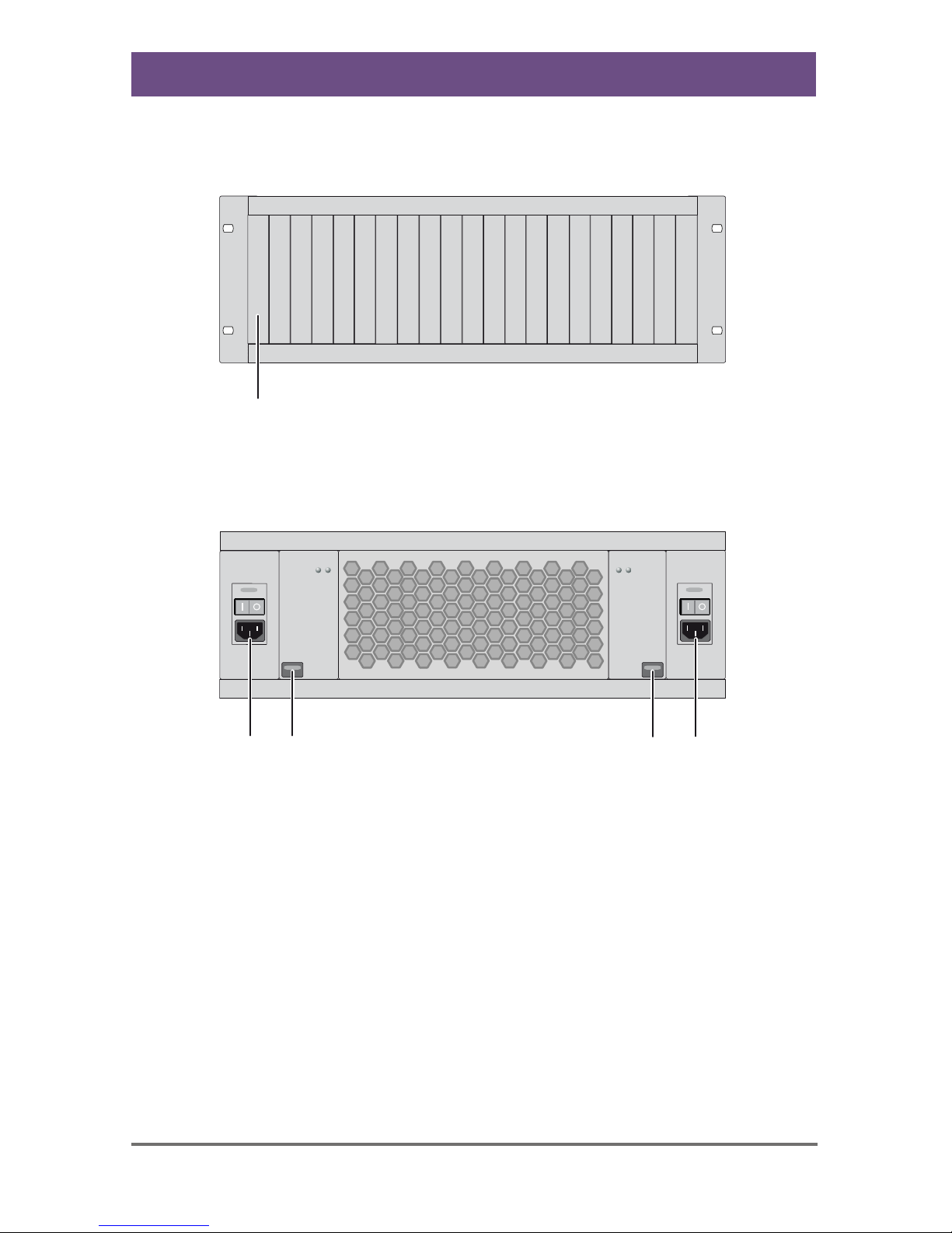
3.6.7 21-fold Vario Chassis 474-BODY21R
CPU and CON Unit
1
Rear View
1 Slots for modules #1 - #21
1234
Front View
1 Connect to power supply 2
2 Locking for power supply 2 (redundancy)
3 Locking for power supply 1 (standard)
4 Connect to power supply 1
Pos: 18 /806-IHSE/ Beschreibung/Gerä teansichten/485- xx/485-BC @ 11\mod_1395 150015320_6.doc @ 140874 @ 3 @ 1
Draco (Cross) Repeater
18 2014-04-15
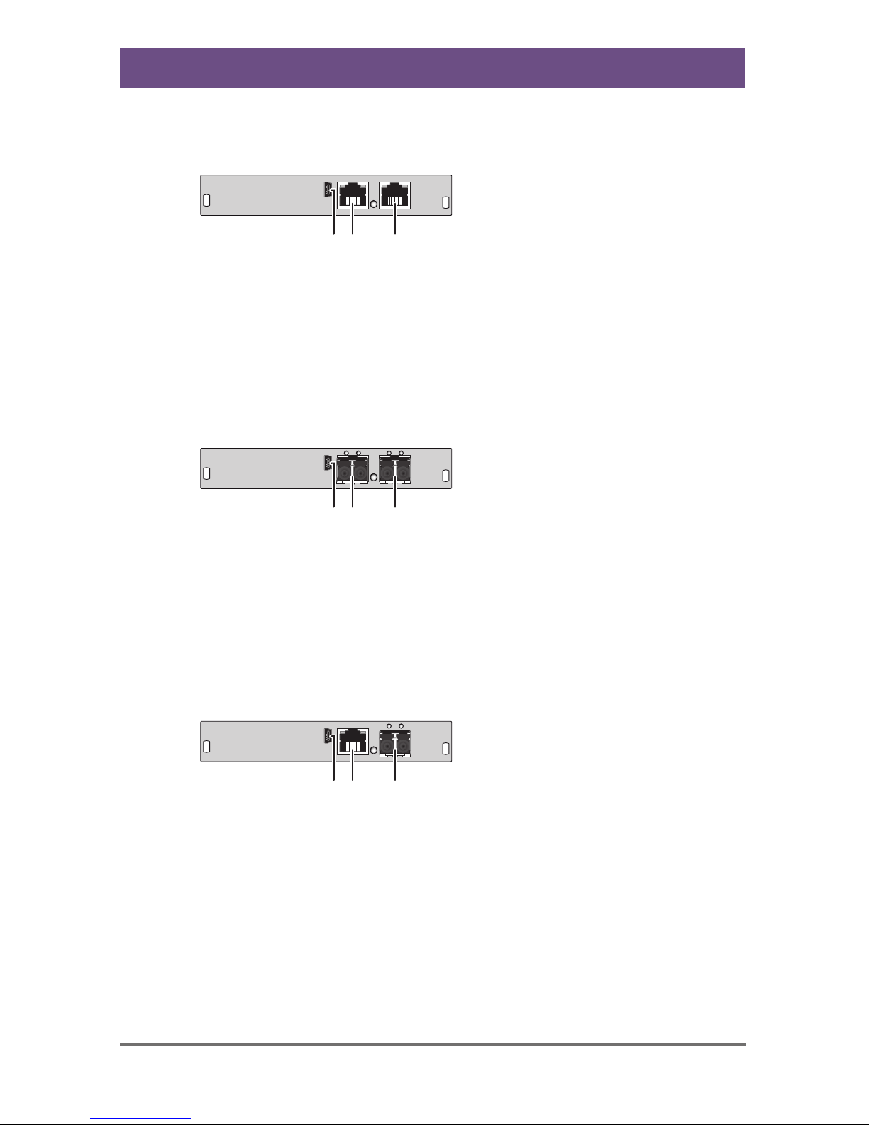
3.6.8 Model 485-BC
Module
12 3
Rear View
1 Service port
2 Connect to interconnect cable 1
3 Connect to interconnect cable 2
Pos: 19 /806-IHSE/ Beschreibung/Gerä teansichten/485- xx/485-BS @ 11\mod_1395151 298709_6.doc @ 140905 @ 3 @ 1
3.6.9 Model 485-BS
Module
12 3
Rear View
1 Service port
2 Connect to interconnect cable 1
3 Connect to interconnect cable 2
Pos: 20 /806-IHSE/ Beschreibung/Gerä teansichten/485- xx/485-BX @ 11\mod_1395153 879791_6.doc @ 140936 @ 3 @ 1
3.6.10 Model 485-BX
Module
12 3
Rear View
1 Service port
2 Connect to interconnect cable 1
3 Connect to interconnect cable 2
Pos: 21 /806-IHSE/ Beschreibung/Gerä teansichten/485- xx/485-BCC @ 11\mod_1395 153925309_6.doc @ 140967 @ 3 @ 1
Description
2014-04-15 19
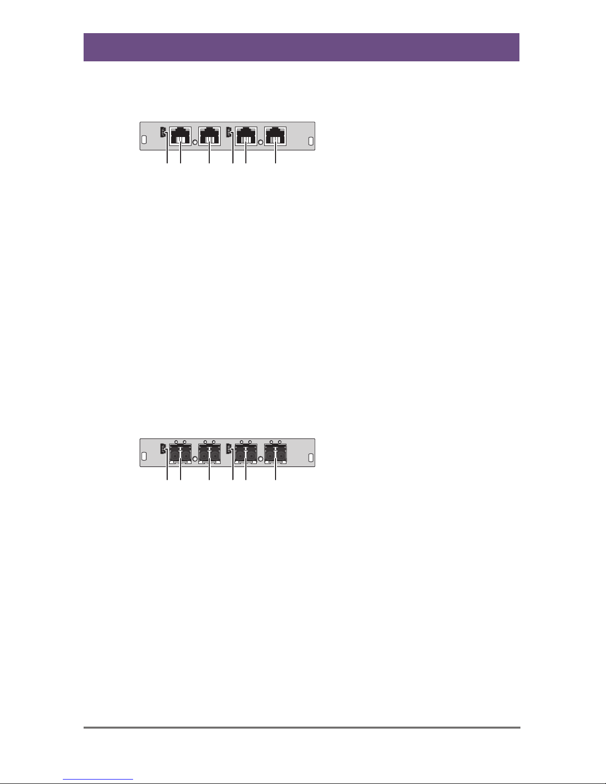
3.6.11 Model 485-BCC
Module
142 3 65
Rear View
1 Service port (repeater #1)
2 Connect to interconnect cable 1
(repeater #1)
3 Connect to interconnect cable 2
(repeater #1)
4 Service port (repeater #2)
5 Connect to interconnect cable 1
(repeater #2)
6 Connect to interconnect cable 2
(repeater #2)
Pos: 22 /806-IHSE/Besc hreibung/Gerätea nsichten/485-xx/48 5-BSS @ 11\mod_13951540112 82_6.doc @ 140998 @ 3 @ 1
3.6.12 Model 485-BSS
Module
2 3 5 6
14
Rear View
1 Service port (repeater #1)
2 Connect to interconnect cable 1
(repeater #1)
3 Connect to interconnect cable 2
(repeater #1)
4 Service port (repeater #2)
5 Connect to interconnect cable 1
(repeater #2)
6 Connect to interconnect cable 2
(repeater #2)
Pos: 23 /806-IHSE/Besc hreibung/Gerätea nsichten/485-xx/48 5-BXX @ 11\mod_13951540808 63_6.doc @ 141029 @ 3 @ 1

Draco (Cross) Repeater
20 2014-04-15
3.6.13 Model 485-BXX
Module
2 3 5 6
14
Rear View
1 Service port (repeater #1)
2 Connect to interconnect cable 1
(repeater #1)
3 Connect to interconnect cable 2
(repeater #1)
4 Service port (repeater #2)
5 Connect to interconnect cable 1
(repeater #2)
6 Connect to interconnect cable 2
(repeater #2)
Pos: 24 /806-IHSE/ Beschreibung/Di agnose LEDs/UEB_Diagnos e_LEDs @ 6\mod_13045840047 23_6.doc @ 51146 @ @ 1
This manual suits for next models
6
Table of contents
Other Ihse Repeater manuals


