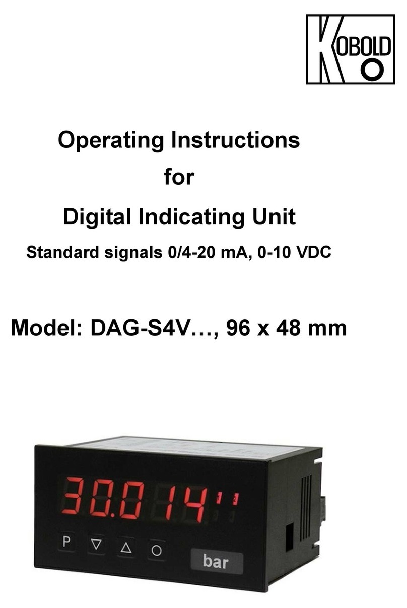
Iijima MA-300 User manual

MA300TS-0210
□□□□□□□□□□□□□□□□□□□□□□□□□□□□□□□
DO Measuring Device / MA-300
Operation Manual
□□□□□□□□□□□□□□□□□□□□□□□□□□□□□□□
Thank you for purchasing the IIJIMA DO Measuring Device, model MA-300.
This device can measure the dissolved oxygen (DO) in fluid using the optional residual oxygen meter PACK
MASTER, model RO-105S and a stirrer.
This manual describes how to operate the DO Measuring Device and the precautions that must be observed to
ensure proper and safe use. Always read this manual and fully understand the operation before starting use.
Keep this manual near the device for quick reference at any time.

MA300TS-0210
Table of Contents
1. Safety precautions
・・・・・・・・・・・・・・・・・・・・・・・・・・・・・・・・・・・・・・・・・・・・・・・・・・・・・・・・・・・・・・・・・・・・・・・・
1
2. Confirmation of package contents
・・・・・・・・・・・・・・・・・・・・・・・・・・・・・・・・・・・・・・・・・・・・・・・・・・・・・・・・・・
2
(1) Package contents・・・・・・・・・・・・・・・・・・・・・・・・・・・・・・・・・・・・・・・・・・・・・・・・・・・・・・・・・・・・・・・・・・・・・ 2
(2) Accessories (options)・・・・・・・・・・・・・・・・・・ ・・・・・・・・・・・・・・・・・・・・・・・・ ・・・・・・・・・・・・・・・・・・・ 3
3. Names and functions of each part
・・・・・・・・・・・・・・・・・・・・・・・・・・・・・・・・・・・・・・・・・・・・・・・・・・・・・・・・・・
4
(1) Main unit display area (LCD display area)・・・・・・・・・・・・・・・・・・・・・・・・・・・・・・・・・・・・・・・・・・・・・・・・ 5
(2) Connection procedures・・・・・・・・・・・・・・・・・・・・・・・・・・・・・・・・・ ・・・・・・・・・・・・・・・・・・・・・・・・・・・・・・ 5
4. Preparing for measurement
・・・・・・・・・・・・・・・・・・・・・・・・・・・・・・・・・・・・・・・・・・・・・・・・・・・・・・・・・・・・・・・・・
6
(1) PACK MASTER (RO-105S) settings・・・・・・・・・・・・・・・・・・・・・・・・・・・・・・・・・・・・・・・・・・・・・・・・・・・・・ 6
1. Measurement Mode (O2/DO) setting・・・・・・・・・・・・・・・・・・・・・・・・・・・・・・・・・・・・・・・・・・・・・・・・・・・ 6
2. DO Display (DO [mg/L] / Saturation rate [%] setting・・・・・・・・・・・・・・・・・・・・・・・・・・・・・・・・・・・・・・ 7
3. Setting the Span Calibration Method (Saturated water calibration/air calibration) ・・・・・・・・ ・8
(2) Span calibration・・・・・・・・・・・・・・・・・・・・・・・・・・・・・・・・・・・・・・・・・・・・・・・・・・・・・・・・・・・・・・・・・・・・・・・ 9
1. Air calibration method・・・・・・・・・・・・・・・・・・・・・・・・・・・・・・・・・・・・・・・・・・・・・・・・・・・・・・・・・・・・・・・ 9
2. Saturated water calibration method・・・・・・・・・・・・・・・・・・・・・・・・・・・・・・・・・・・・・・・・・・・・・・・・・・・ 10
(3) Zero calibration・・・・・・・・・・・・・・・・・・・・・・・・・・・・・・・・・・・・・・・・・・・・・・・・・・・・・・・・・・・・・・・・・・・・・・・ 11
(4) Water temperature adjustment・・・・・・・・・・・・・・・・・・・・・・・・・・・・・・・・・・・・・・・・・・・・・・・・・・・・・・・・・・ 12
5. Measurement
・・・・・・・・・・・・・・・・・・・・・・・・・・・・・・・・・・・・・・・・・・・・・・・・・・・・・・・・・・・・・・・・・・・・・・・・・・・・・
13
(1) Measuring a sample (Sample that does not contain fibers or solids)・・・・・・・・・・・・・・・・・・・・・・・・・・ 13
(2) Repeated measurement・・・・・・・・・・・・・・・・・・・・・・・・・・・・・・・・・・・・・・・・・・・・・・・・・・・・・・・・・・・・・・・ 15
(3) Measuring a sample containing fibers or solids・・・・・・・・・・・・・・・・・・・・・・・・・・・・・・・・・・・・・・・・・・・・ 15
6. Maintenance
・・・・・・・・・・・・・・・・・・・・・・・・・・・・・・・・・・・・・・・・・・・・・・・・・・・・・・・・・・・・・・・・・・・・・・・・・・・・・
16
(1) Cleaning after measurement・・・・・・・・・・・・・・・・・・・・・・・・・・・・・・・・・・・・・・・・・・・・・・・・・・・・・・・・・・・ 16
1. Cleaning the MA-300・・・・・・・・・・・・・・・・・・・・・・・・・・・・・・・・・・・・・・・・・・・・・・・・・・・・・・・・・・・・・・・16
2. Cleaning and storing the oxygen sensor・・・・・・・・・・・・・・・・・・・・・・・・・・・・・・・・・・・・・・・・・・・・・・ 16
(2) Replacing the oxygen sensor membrane and electrolytic solution・・・・・・・・・・・・・・・・・・・・・・・・・・・ 16
7. Troubleshooting
・・・・・・・・・・・・・・・・・・・・・・・・・・・・・・・・・・・・・・・・・・・・・・・・・・・・・・・・・・・・・・・・・・・・・・・・・
17
8. Error Messages
・・・・・・・・・・・・・・・・・・・・・・・・・・・・・・・・・・・・・・・・・・・・・・・・・・・・・・・・・・・・・・・・・・・・・・・・・・
19

1
MA300TS-0210
1. Safety Precautions
This section explains the precautions that must be observed to prevent injury to the user or other persons or damage to
property.
The following symbols classify and explain the degree of harm or property damage that may result if the contents of the
symbols are ignored and the product is used improperly.
This symbol indicates the extent of harm or damage that could potentially result in
injury or physical damage if the information is ignored and the product is handled
incorrectly.
This symbol indicates a situation in which the measurement could be adversely
affected, preventing correct measurement results from being obtained if the
information is ignored and the product is handled incorrectly.
If a 3-way check valve is inadvertently used when measuring a sample containing fibers or solids, the
valve could become clogged, and the measurement will not be possible. Exchange the 3-way check
valve with the enclosed 3-way cock. (Refer to section “5. Measurement (3) Measuring a sample
containing fibers or solids” on page 15 of this manual.)
The key components are made of acrylic materials. Acrylic materials have a low resistance to solvents
such as alcohol, so do not measure such matters. The acrylic material could be adversely affected, such
as cracking the acrylic material.
Avoid taking measurements in conditions where the temperature changes. Temperature changes may
cause air bubbles to form in the sample being measured, and this may cause measurement errors.
If there is a temperature difference between the measurement sample and this device, make sure to
match the temperatures before measurement.
For example, if the sample has been stored in a refrigerator, let it sit until it reaches room temperature,
and then measure, taking care not to inhale any of the air bubbles generated.
Samples containing milkfat ingredients should be measured at the end of the measurement session.
After measuring, clean the device thoroughly.

2
MA300TS-0210
* When the product is shipped, the
tubing part is not connected.
2. Confirmation of package contents
When unpacking the DO Measuring Device, confirm that the following items are included and that the contents have not
been damaged. If any parts are missing or damaged, contact the dealer from which you purchacedthe product.
(1) Package contents
Description Quantity
(1)
→
1
(2) Oxygen sensor (WAGNIT®) (Model: WA-BRM5)
Membrane solution set (Model: GT-41) x 1 set is enclosed.
* “WAGNIT®” is a registered trademark of the Iijima Electronics
Corporation oxygen sensor.
1
(3) Maintenance parts (spare parts)
Lifelon tubing (Φ2×4 mm)1.5 m
[Manufacturer] KOKUGO Co., Ltd. [Part No.] 02-048-01-02
3-way check valve x 1 pc.
[Manufacturer] ISIS Co., Ltd. [Part No.] VCV1251
1 set
(4) 3-way cock (Part for measuring samples containing fibers or solids)
Model: VXB1079 Manufacturer: ISIS Co., Ltd.
Material: Polycarbonate/polyethylene
1
(5) Cleaning brush
Part name: Blood sedimentation brush
(Model: 7-5611-01)
Distributor: AS ONE Corporation
1
(6) Anhydrous sodium sulfite, Guaranteed Reagent 100 g pack
(For preparing zero-calibration solution)
1
(7) Operation manual (this document) 1
* When purchasing additional consumable parts or spare parts for items (3) to (6), please refer to the part names and
models indicated above and contact your dealer or a laboratory equipment dealer.
With 3-way
check valve
Beaker
(with tubing holder)
Magnetic stir bar
DO measuring device (Model: MA
-300)
Housing section
(enlarged)
Syringe section
(enlarged)

3
MA300TS-0210
(2) Accessories (options)
Description
(8) Stirrer (model: KK)
Product name: Ultra-Flat Digital Mini Magnetic Stirrer
Distributor: KENIS, Ltd.

4
MA300TS-0210
3. Names and functions of each part
This device is shipped with part of the tubing parts removed so that excessive load is not applied on each part. Before
starting use, refer to the schematic drawing below, connect each part, and install the device. The tubing is manually
tightened with a luer fitting.
Do not use a tool when connecting the parts. Tightening with a tool could result in part
damage.
Securely tighten the parts by hand without using tools.
<Schematic drawing> *PACK MASTER and stirrer are sold separately.
The following photo shows the overall view, including the optional PACK MASTER (model: RO-105S), Stirrer (Model: KK),
and sample prepared by the user.
DO sensor connector
DO sensor
connector
← The model and serial number are
indicated on the cable.
Water
temperature
sensor
<Back panel of PACK MASTER>
<Oxygen (DO) sensor>

5
MA300TS-0210
(1) Main unit display area (LCD display area)
The following screen appears when the oxygen sensor (WA-BRM5) is connected to the PACK MASTER and the DO
measuring mode is set.
(Refer to section “4. Preparing for measurement (1) PACK MASTER (RO-105S) settings” on page 6 for details on setting
the measurement mode.)
<When DO MEASURE screen [mg/L] is displayed>
(2) Connection procedures
Step 1. Connect the PACK MASTER and oxygen sensor.
Remove the black cap attached to the DO
sensor connector (marked with “DO IN”) on the
back panel of the PACK MASTER.
Remove the pin shorting cap from the oxygen
sensor and connect the connector part.
Carefully align the connector pins with the
position of the hole. Connect the connector
and turn the coupling to fix it.
Step 2. Connect the tubing between the syringe and housing.
Step 3. Install the stirrer.
Place the magnetic stir bar in the housing.
Place the housing over the stirrer and turn the stirrer power
ON. Adjust the position so that the magnetic stir bar comes
to the center of the housing.
Finely adjust the position when mixing with the stirrer during
the measurement.
Pin shorting cap
Coupling
Magnetic stir bar
Date and Time
Title
Battery level
(O
2
MEASURE /
DO MEASURE)
DO
measurement value
Unit
Water temperature
Operation guide
display

6
MA300TS-0210
4. Preparing for measurement
(1) PACK MASTER (RO-105S) settings
Before starting the DO measurement, set and confirm the 1. Measurement mode, 2. DO display, and 3. Span calibration
method on the PACK MASTER main unit.
The set details are saved even if the PACK MASTER power is turned OFF, the batteries are removed, or the AC adapter
is disconnected. Note that the details are not saved when the oxygen sensor (WA-BRM5) is disconnected.
1. Measurement Mode (O2/DO) setting
Step 1. Confirm that the oxygen sensor (WA-BRM5) is connected.
Step 2. Turn the PACK MASTER power ON, and press on the Measurement Standby screen.
The mode switches to the DO MEASURE mode.
<When O2MEASURE is displayed> <When DO MEASURE is displayed>
The display alternates in the following order each time is pressed.
DO MEASURE cannot be selected unless the oxygen sensor (WA-BRM5) is connected to the
PACK MASTER (RO-105S).
The mode cannot be selected when the PACK MASTER’s key lock function is enabled.
Disable the key lock function before selecting the mode. (Refer to the “Key Lock / Unlock
Function” section in the PACK MASTER Operation Manual for details on the operation.)

7
MA300TS-0210
2. DO Display (DO [mg/L] / Saturation rate [%] setting)
Step 1. Turn the PACK MASTER power ON, and press on the O2Measurement Standby screen or DO
MEASURE screen.
The MENU screen opens, and “CAL” is selected (flashes).
Step 2. Press once.
The cursor moves, and “SET” is selected (flashes).
Step 3. Press .
The SETTING MENU screen opens, and “O2DISP SET” is selected
(flashes).
Step 4. Press three times.
The cursor moves, and “DO DISP SET” is selected (flashes).
Step 5. Press .
The DO DISP SET screen opens, and the selected setting flashes.
* The factory default setting is “DO mg/L”.
Step 6. Each time is pressed, the display changes as shown below.
<When DO mg/L is displayed> <When SATUR-R % is displayed>
<When set to DO mg/L>
Step 7. When is pressed, the selected settings are saved.
The SETTING MENU screen opens.

8
MA300TS-0210
3. Setting the Span Calibration Method (Saturated water calibration/air calibration)
Step 1. Turn the PACK MASTER power ON, and press on the O2Measurement Standby screen or DO
MEASURE screen.
The MENU screen opens, and “CAL” is selected (flashes).
Step 2. Press once.
The cursor moves, and “SET” is selected (flashes).
Step 3. Press .
The SETTING MENU screen opens, and “O2DISP SET” is selected
(flashes).
Step 4. Press four times.
The cursor moves, and “DO CAL SET” is selected (flashes).
Step 5. Press .
The DO CAL SET screen opens, and the selected setting flashes.
* The factory default setting is “AIR”.
Step 6. Each time is pressed, the display changes between “AIR” and “SATUR WATER”.
<When AIR is displayed> <When SATUR WATER is displayed>
Display symbol Name
AIR Air calibration
SATUR WATER
Saturated water
calibration
<When Set to AIR is selected>
Step 7. When is pressed, the selected settings are saved.
The SETTING MENU screen opens.

9
MA300TS-0210
(2) Span calibration
Perform span calibration once a day before starting measurements using the following procedure.
There are two types of span calibration: air calibration and saturated water calibration. Refer to the following explanation
and procedure, and select the span calibration method that matches your application.
1. Air calibration method
This simple calibration method calibrates using the atmosphere.
It is an easy calibration method, but it may be affected by changes in the atmospheric temperature around the water
temperature sensor.
Step 1. Release the oxygen sensor to the atmosphere and stabilize the temperature.
The sensor cannot be calibrated accurately if the temperature changes. Sufficiently stabilize the temperature
when the atmospheric temperature is stable, such as before turning on the air conditioning.
Step 2. Change the instrument setting to “Set to AIR”. (Perform only the first time.)
Refer to section “3. Setting the Span Calibration Method (Saturated water calibration/air calibration)” on page 8
of this manual.
Step 3. When the DO MEASURE screen is displayed, press .
The MENU screen opens, and “CAL” is selected (flashes).
Step 4. Press .
The DO CAL screen opens.
Step 5. When the indicated value stabilizes, hold down for 1
second or longer.
The stability is decided, and after approx. 10 seconds “CAL complete” appears to indicate that the calibration is
complete.
The DO MEASURE screen opens when the calibration is completed.
The calibration value is saved even if the PACK MASTER power is turned OFF, the batteries are removed, or
the AC adapter is disconnected.
If an error message appears during the calibration, refer to the “Error Messages” section on page 19 of this
manual and the “Error Messages” section in the PACK MASTER Operation Manual.
<Display example>

10
MA300TS-0210
2. Saturated water calibration method
This calibration method follows JIS K0102. Calibration is performed using saturated water with dissolved oxygen
(hereinafter, saturated water).
Step 1. Prepare the saturated water.
Fill a beaker with water, and perform aeration. (500 mL of water must be aerated for approx. 10 to 20 minutes.)
Step 2. Change the PACK MASTER setting to “SATUR WATER”. (Perform only the first time.)
Refer to section “3. Setting the Span Calibration Method (Saturated water calibration/air calibration)” on page 8
of this manual.
Step 3. Fill the housing with saturated water.
Refer to Steps 1 to 4 in section “5. Measurement (1) Measuring a sample” on page 13 of this manual.
Step 4. Spin the stirrer and mix the saturated water in the housing.
Allow five to ten minutes for the temperature to stabilize.
If the temperature varies, it can take approximately one minute per degree Celsius to stabilize.
Step 5. When the DO MEASURE screen is displayed, press .
The MENU screen opens, and “CAL” is selected (flashes).
Step 6. Press .
The DO CAL screen opens.
Step 7. When the indicated value stabilizes, hold down for 1 second
or longer.
The stability is decided, and after approx. 10 seconds “CAL complete”
appears to indicate that the calibration is complete.
The DO MEASURE screen opens when the calibration is completed.
The calibration value is saved even if the PACK MASTER power is turned OFF, the batteries are removed, or
the AC adapter is disconnected.
If an error message appears during the calibration, refer to the “Error Messages” section on page 19 of this
manual, and the “Error Messages” section in the PACK MASTER Operation Manual.
Prepare the saturated water at the time of use, not in advance.
<Display example>

11
MA300TS-0210
If an error message appears during the calibration, refer to the “Error Messages” section on page 19 of this
manual, and the “Error Messages” section in the PACK MASTER Operation Manual.
(3) Zero calibration
To measure low concentrations accurately, or if the value when measuring low concentrations seems abnormal (negative
display or a higher value than usual), perform zero calibration following the procedure below.
Step 1. Prepare the zero standard liquid (zero water).
Dissolve 5 g of sodium sulfite in a container such as a beaker, and add water so that the total volume is 100 mL.
(When preparing enough liquid to change the entire amount, adjust with the same ratio.)
Stir until the sodium sulfite completely dissolves. The sodium sulfite will dissolve more easily if added to the water
while stirring. Avoid making air bubbles when stirring.
Step 2. Directly place the oxygen sensor in the container holding the zero water. (The housing is not used.)
Wait approx. ten minutes for the indicated value to drop to about 0.00 mg/L.
Make sure that there are no air bubbles on the tip of the sensor.
Step 3. When the DO MEASURE screen is displayed, press .
The MENU screen opens, and “CAL” is selected (flashes).
Step 4. Press .
The DO CAL screen opens.
Step 5. When the indicated value stabilizes, hold down for 1
second or longer.
The stability is decided, and after approx. 10 seconds “CAL complete”
appears to indicate that the calibration is complete.
The DO MEASURE screen opens when the automatic calibration is completed. The calibration value is saved
even if the PACK MASTER power is turned OFF, the batteries are removed, or the AC adapter is disconnected.
Step 6. Wash the oxygen sensor with tap water filled in a container such as a beaker.
Refer to section “6. Maintenance (1) Cleaning after the measurement” on page 16 of this manual.
Prepare the zero water at the time of use, not in advance.
Perform zero calibration with a container such as a beaker. Do not use the housing. If the zero
water passes through the housing, the residual amount of zero water left in the housing or tubing
after zero calibration could affect the ensuing sample measurement values.
When the zero calibration is completed, always clean the oxygen sensor with tap water. If a
measurement is performed without cleaning the sensor, the residual zero water could affect the
measurement values.
Always clean the oxygen sensor with tap water filled in a container such as a beaker. If cleaned
with tap water directly from the faucet, the pressure of the water could break the membrane on the
sensor surface.
<Display example>

12
MA300TS-0210
(4) Water temperature adjustment * The water temperature is adjusted at the time of shipment, so
normally, this procedure is not required.
If the deviation of the sample water’s temperature is a concern, the water temperature display can be adjusted manually
using a standard thermometer. The temperature can be adjusted in the range of -5°C to +5°C from the currently
displayed temperature.
Step 1. Prepare water at a temperature similar to the sample water currently being
measured in a constant temperature bath, etc.
Set the oxygen sensor (WA-BRM5) and standard thermometer in the
prepared water.
Mix with a stirrer, etc., and allow the water to stabilize for approx. 5 minutes.
Ensure that the water temperature sensor section of the oxygen sensor is
completely submerged in the water.
(The sensor is not completely waterproof, so do not submerge the entire sensor.)
Step 2. Turn the PACK MASTER power ON, and press on the O2
Measurement Standby screen or DO MEASURE screen.
The MENU screen opens, and “CAL” is selected (flashes).
Step 3. Press twice.
The cursor moves, and “FUNC” is selected (flashes).
Step 4. Press .
The FUNC MENU screen opens, and “CLOG CHECK” is selected
(flashes).
Step 5. Press four times.
The cursor moves, and “WTR TEMP ADJ” is selected (flashes).
Step 6. Press .
The “DO°C1-P ADJUST” screen opens.
Step 7. Change the water temperature to be adjusted with the following steps.
Press . The cursor will move in the order of
→→→→. When is pressed,
the cursor function will activate.
<Cursor functions>
The water temperature display is
increased by 0.1°C.
The setting is returned to the factory default
setting.
The water temperature display is
decreased by 0.1°C.
Adjustment of the water temperature is
canceled.
The input water temperature value is saved in the main unit, and the FUNC MENU screen opens.
Step 8. Select ,, or , and then press .
The process to save the water temperature adjustment value is completed or canceled (initialization is completed
when initializing), and then the FUNC MENU screen opens.
Submerge
to this line
WA-BRM5
Water
temperature
sensor
<Display example>

13
MA300TS-0210
5. Measurement
This device is an option for the PACK MASTER (RO-105S). Dissolved oxygen (DO) in liquid can be measured with
limited exposure to air using this device.
The measurement value can be measured and saved as either the dissolved oxygen amount (mg/L) or dissolved oxygen
saturation rate (%).
When the ambient temperature changes, such as when the measurement environment has
changed due to unpacking or relocation of the device installation place, the temperature
change may cause the indicated value to fluctuate gradually. In this case, set the oxygen
sensor in this device and expose it to the atmosphere for 30 minutes or longer so that the
temperature sufficiently stabilizes
Do not use a 3-way check valve to measure samples containing fibers or solids.
When measuring a sample containing fibers or solids, refer to section “5. Measurement (3)
Measuring a sample containing fibers or solids” on page 15 of this manual.
(1) Measuring a sample (Sample that does not contain fibers or solids)
Step 1. Carefully mount the oxygen sensor (WA-BRM5) on the housing unit.
Do not insert the oxygen sensor forcefully.
Forcefully inserting the sensor can apply a load on the
membrane and affect the measurement value.
If there is a gap between the oxygen sensor and
housing unit, the solution will not be mixed properly
and the measurement value will be affected.
Completely insert the oxygen sensor into the back of
the housing so that there is no gap.
Step 2. Set the sample.
Avoid exposing the sample to the atmosphere when
setting it. Set the suction tubing so it is as close to the
bottom as possible.
When suctioning the sample, suction from the bottom
of the container as much as possible. If the sample is
taken from close to the water surface, the air may
dissolve in the sample and cause a measurement
error.
T
ip of suction tubing

14
MA300TS-0210
Step 3. Using a syringe, feed the sample into the housing.
Slowly pull out the syringe plunger taking approx. 5 seconds to suction 10 mL of the
sample. Then slowly push in the syringe plunger taking approx. 5 seconds to discharge
all of the sample solution in the syringe.
(The sample is fed into the housing with this suction and discharge process.)
Slowly move the syringe plunger so that air bubbles do not form in the measurement
sample in the housing.
When suctioning for the first time, air bubbles will enter the syringe. Hold the syringe
upwards and move the plunger to discharge the air bubbles.
Step 4. Repeat this suction and discharge process.
Repeat the suction and discharge process in Step 3 one to two times to feed a total of 20 to 30 mL of sample
into the housing. The syringe does not need to be facing upward after the second time.
Step 5. Spin the stirrer to mix the solution.
The automatic stability decision function automatically decides the stability of the indicated value, and holds the
stabilized value.
The “automatic stability decision function” eliminates the read indicated value variation. When the
measurement is started, the stability of the indicated value is automatically decided and is then held or
canceled.
If the stirrer is rotated at high speed, the magnetic stir bar may pop off with force and damage the
oxygen sensor. Gradually increase the stirrer speed.
If the stirrer speed is too slow, the flow will be insufficient, and the measurement value may be low.
Adjust the speed to the maximum speed that does not cause the magnetic stir bar to pop off.
The recommended speed for the stirrer (Model: KK accessory) is 1,100 to 1,400 rpm.
(For similar viscosity as water)
To ensure an accurate measurement, adjust the stirrer speed during calibration and measurement.
Step 6. To save the measurement value in the main unit, press the k e y.
”Save Complete” is displayed, and the previous stability decision value is saved in the measurement history by
the memory function.
The “Memory Function” saves the held measurement value as the measurement history. If the key is
pressed while “Save” is displayed, the measured value will be saved in the main unit as the measurement
history. The saved details are retained even if the power is turned OFF, the batteries are removed, or the AC
adapter is disconnected.
Press on the Measurement Standby Screen to confirm the measurement history. The Measurement
History Screen will open. Refer to the “Measurement and recording” section in the PACK MASTER Operation
Manual for details on the functions and operations.
Progress status
<Display during measurement>
<Display in hold state>
Operation icon
d
isplay
“Save” display

15
MA300TS-0210
(2) Repeated measurement (repeatedly measuring several samples)
To measure multiple samples repeatedly, repeat Step 2 to Step 5 in section “5. Measurement (1) Measuring a sample” on
page 13 of this manual.
There is no need to operate the syringe in an upward direction during Step 3 in this case.
When measuring a 350 mL sample, complete the measurement within three minutes of opening
the plug. If it takes longer, the oxygen in the atmosphere will cause the measurement value to be
higher.
(3) Measuring a sample containing fibers or solids
Step 1. Exchange the 3-way check valve with the 3-way cock.
3-way check valve 3-way cock
Step 2. Take the measurement while switching the lever position for suctioning and discharge.
Refer to the syringe operation explained in Step 3 of section “5. Measurement (1) Measuring a sample” on page
14 of this manual, and take the measurement.
[Cock position during suction and discharge]
Switch the lever on the 3-way cock as shown in the photo and suction and discharge the sample.
Lever position for suction Lever position for discharge
E
xchange

16
MA300TS-0210
6. Maintenance
(1) Cleaning after measurement
1. Cleaning the MA-300
When finished measuring the sample, discharge the sample remaining in the syringe, housing, and tubing. Suction and
discharge tap water by operating the syringe in the same manner as measuring a sample.
If the parts are heavily contaminated, clean with a neutral detergent, etc., and allow to dry. If the injection inlet or discharge
outlet of the housing, etc., are clogged, use the enclosed cleaning brush to remove the clogged matter.
Never use an ultrasonic cleaner to clean the parts. There is a risk of cracking.
Never use alcohol or solvent when cleaning. There is a risk of housing clouding or cracking.
Before removing the oxygen sensor, remove all sample solution and tap water in the device
and make sure that negative pressure is not generated in the housing. Negative pressure in
the housing could damage the oxygen sensor’s membrane.
2. Cleaning and storing the oxygen sensor
Clean the oxygen sensor when finished with zero calibration or measuring the sample.
Step 1. Fill a container, such as a beaker with tap water, and lightly rinse the oxygen sensor in the container.
Always clean the oxygen sensor with tap water filled in a container. If cleaned with tap water directly from the
faucet, the pressure of the water could break the membrane on the sensor surface.
Step 2. Wipe off the moisture lightly with tissue paper and store the sensor in the atmosphere.
When removing the oxygen sensor from the
main unit and storing it, always attach the pin
shorting cap as shown on the right to maintain
the quality.
(2) Replacing the oxygen sensor membrane and electrolytic solution
In principle, the oxygen sensor (WA-BRM5) will degrade over time. The oxygen sensor membrane and electrolytic
solution must be replaced in the following cases. When making the replacement, use the enclosed “Membrane solution
set (Model: GT-41).”
Refer to the replacement procedures in the “Maintenance Guide” enclosed with the oxygen sensor and correctly replace
the parts.
When the “Sensor Error” message is displayed.
When the measurement value stabilizing time is slow.
When residues appear in the oxygen sensor’s electrolytic solution. (White or yellow powder, etc.)
When use has been suspended for a long time (several months).
When the membrane is damaged.
Pin shorting cap
View from pin side
Pin shorting cap

17
MA300TS-0210
7. Troubleshooting
If you suspect any malfunction or trouble, always perform the following confirmation and remedy before requesting repairs.
If the symptoms do not subside, contact the dealer from which you purchased the product.
Symptom
Confirmation
Action
The value is high.
The value does not change
(does not lower).
Was air inadvertently suctioned
during the measurement?
Dispose of the sample solution being
measured, and
start the measurement from the
beginning.
Was the span calibrated? Calibrate the span. (Refer to pages 9 to 10.)
Was the membrane on the tip of
the oxygen sensor facing
upward when calibrating the
span?
Point the membrane on the tip of the oxygen
sensor downward or to the side when
calibrating the span.
Is the oxygen sensor being used
after being suspended for a long
time (several months)?
The oxygen sensor membrane and electrolytic
solution may be degraded. Replace the
membrane and electrolytic solution with new
ones. After replacing, allow the sensor to
stabilize for several hours to 12 hours or more,
and then calibrate it.
Is the membrane on the top of
the oxygen sensor
contaminated?
Clean the oxygen sensor and remove the
contaminants. (Refer to section “6.
Maintenance (1) Cleaning after measurement”
on page 16.)
If the contaminants cannot be removed,
replace the membrane and electrolytic solution
with new ones. After rep
lacing, allow the sensor
to stabilize for several hours to 12 hours or
more, and then calibrate it.
Was zero calibration performed?
Perform zero calibration. (Refer to page 11.)
Use zero standard solution (zero water) that
has been prepared just before the calibration,
not solution made in advance.
If the symptoms do not improve
after taking the above actions,
the oxygen sensor may have
reached its life.
Order a new oxygen sensor and replace the old
one.
The value is low. Is the stirrer creating an
appropriate flow?
The measurement value can be low if the
stirrer
speed is too low, causing the flow to be
insufficient. Adjust the speed to the maximum
speed that does not cause the magnetic stir bar
to pop off. (Refer to page 14.)
Was the span calibrated? Calibrate the span. (Refer to pages 9 to 10.)
Was the membrane on the tip of
the oxygen sensor facing
upward when calibrating the
span?
Point the membrane on the tip of the oxygen
sensor downward or to the side when
calibrating the span.

18
MA300TS-0210
Is the oxygen sensor being used
after being suspended for a long
time (several months)?
The oxygen sensor membrane and electrolytic
solution may be degraded. Replace the
membrane and electrolytic solution with new
ones. After replacing, allow the sensor to
stabilize for several hours to 12 hours or more,
and then calibrate it.
Is the membrane on the tip of
the oxygen sensor
contaminated?
Clean the oxygen sensor and remove the
contaminants. (Refer to section “6.
Maintenance (1) Cleaning after measurement”
on page 16.)
If the contaminants cannot be removed,
replace the membrane and electrolytic solution
with new ones. After replacing, allow the parts
to stabilize for several hours to 12 hours or
more, and then calibrate.
Was zero calibration performed?
Perform zero calibration. (Refer to page 11.)
Use zero standard solution (zero water) that
has been prepared just before the calibration,
not solution made in advance.
If the symptoms do not improve
after taking the above actions,
the oxygen sensor may have
reached its life.
Order a new oxygen sensor and replace the old
one.
Contaminants have
solidified in the housing.
Fill the housing with lukewarm water and allow it to soak. Then, wipe off the
contaminants with a soft sponge, etc.
If the solution contains oils and fats, soak the sensor in a neutral detergent, and
wipe off the contaminants with a soft sponge, etc.
* Do not use alcohol when cleaning. Do not use a metal brush or hard sponge.
Solids were suctioned with
the sample water and got
clogged in the tubing.
When using the 3-way check valve, replace the 3-way check valve with a new
one.
If the injection section or discharge section is clogged, use the enclosed cleaning
brush and remove the clogged matter as shown in the photo.
<Example of using cleaning brush>
If the cleaning brush is not available, it may be possible to remove the clogged
material by attaching the syringe directly to the injection/discharge section and
applying pressure.
Reference: Refer to the Iijima Electronics Corporation website for information on troubleshooting, handling, and maintenance.
https://www.iijima-e.co.jp/
Contact the dealer from which you purchased the product if you have any questions or inquiries regarding handling.
Table of contents
Other Iijima Measuring Instrument manuals


