Iijima PACK LEADER RO-105LS User manual

Residual Oxygen / Carbon Dioxide Meter
PACK LEADER/RO-105LS
Operation Manual
With Warranty
Thank you for purchasing the PACK LEADER.
The PACK LEADER is an analyzer that samples gas from bags, bottles, cans, etc.,
and measures the residual oxygen concentration (O2), gas replacement rate (REP),
and carbon dioxide concentration (CO2).
This manual describes how to operate the PACK LEADER and the precautions that
must be observed to ensure proper and safe use. Always read this manual and fully
understand the operation before starting use.
Keep this manual near the device for quick reference at any time.
Before starting use
1. Safety precautions
This section explains the precautions that must be observed to prevent injury to the user or other persons
or damage to property.
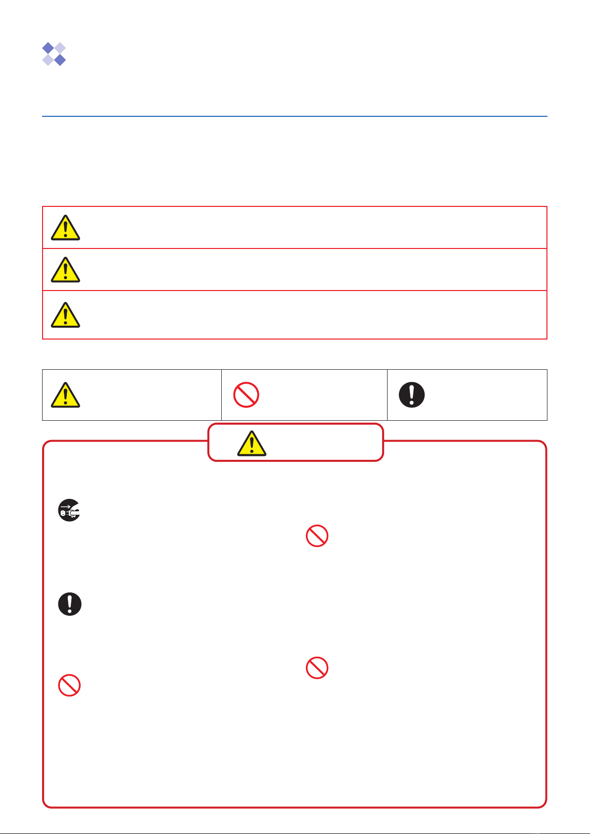
■ Thefollowingsymbolsclassifyandexplainthedegreeofharmorpropertydamagethatmayresultifthe
contents of the symbols are ignored and the product is used improperly.
Warning This symbol indicates a dangerous situation that could result in fatal or
serious injuries if the information is ignored and the product is handled
incorrectly.
Caution This symbol indicates the extent of harm or damage that could potentially
result in injury or physical damage if the information is ignored and the
product is handled incorrectly.
Note
This symbol indicates a situation in which the measurement could
be adversely affected, preventing correct measurement results from
being obtained if the information is ignored and the product is handled
incorrectly.
■ Thetypesofinformationtobeobservedarecategorizedandindicatedwiththefollowingsymbols.
This symbol indicates
“Warnings”, “Cautions”,
and “Notes” that must be
observed.
This symbol indicates
“Prohibited” matters that
must not be conducted.
This symbol indicates
“Instructions” that must
always be enforced.
(Always observe)
Suspend operation immediately when any
abnormality occurs.
Continuing use can lead to fires or electric shocks.
Immediately turn OFF the power switch and
disconnect the power plug from the outlet. Contact
the dealer from which you purchased the product
for repairs.
Take care not to stab the human body with
the needle.
A needle is used for the measurement. Handle it
with extreme caution.
There is a risk of blindness, puncture wounds, or
cuts.
Do not touch the oxygen sensor with bare
hands if it is leaking.
A highly concentrated acetic acid solution is used
for the electrolyte inside the sensor. There is a risk
of serious eye injury if the electrolyte gets into the
eyes. Immediately rinse the eyes (including under
the eyelids) with clean running water for at least 15
minutes, and immediately seek medical attention
from an ophthalmologist.
If the electrolyte gets on the skin, wash with plenty
of water and seek immediate medical attention.
Perform measurements in an adequately
ventilated room.
Do not place your face near the unit or
smell odors during the measurement.
The PACK LEADER samples a mixture of low
oxygen gas or carbon dioxide gas, and discharges
it into the atmosphere when the measurement is
completed.
Conducting measurements in a poorly ventilated
room or taking a deep breath to smell the odors
can cause the user to lose consciousness or feel
unwell due to a lack of oxygen.
Do not touch the battery with bare hands if
it is leaking.
There is a risk of serious eye injury or inflammation
if the fluid leaking from the battery gets in the
eyes or on the skin. Immediately wash with clean
running water, and seek immediate medical
attention.
Warning
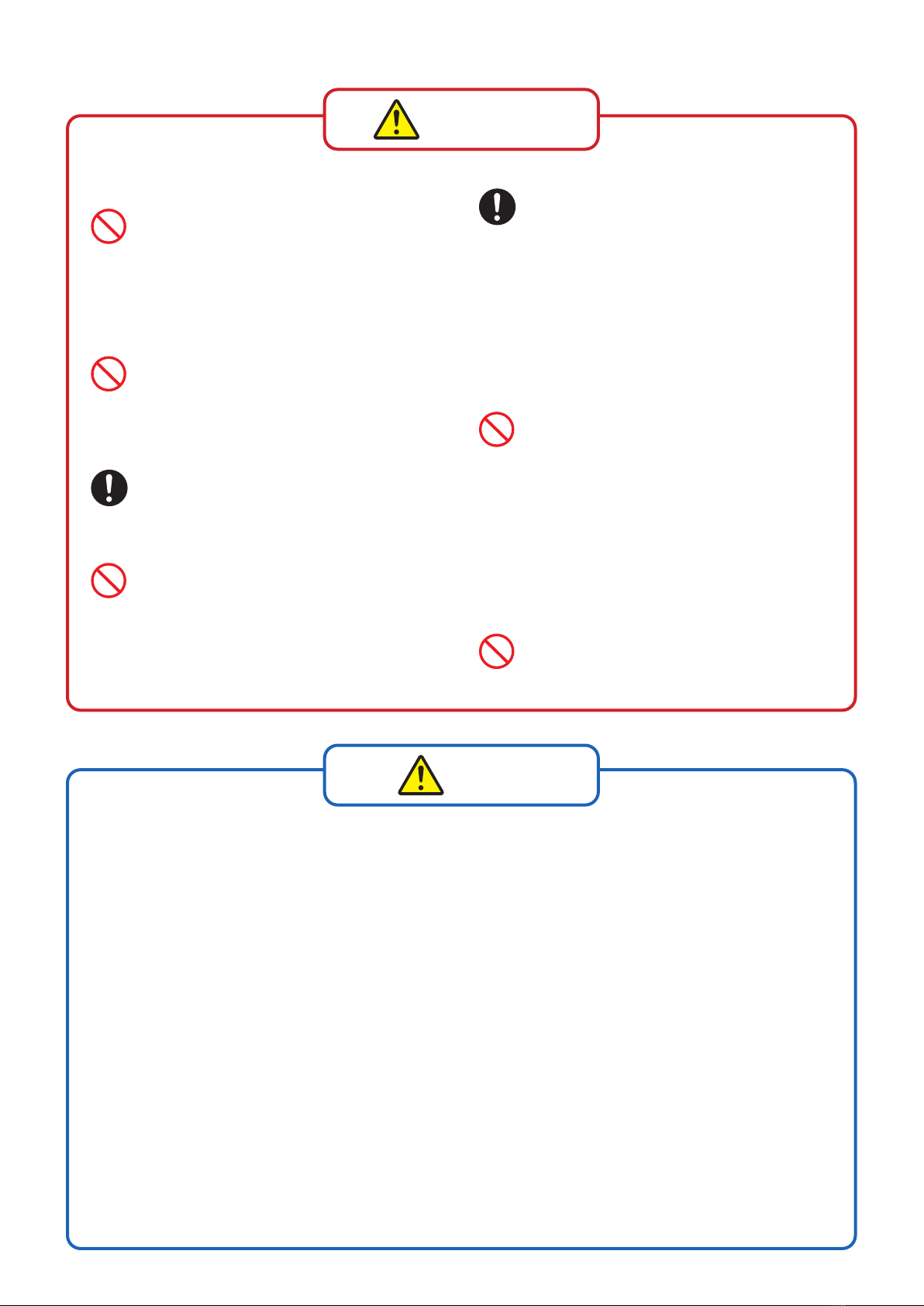
Do not damage the power cord or power
plug.
Do not damage, process, place heavy objects
on, heat, place near a source of heat, forcibly
bend, twist, or pull the power cord or plug. There
is a risk of fire or electric shock resulting from
core wire exposure, short-circuit, or breakage.
Do not use a power plug that is contami-
nated with foreign matter, such as dust.
There is a risk of fire or electric shock if the
foreign matter absorbs moisture, etc., and
causes an insulation fault.
Insert the power plug completely to the
base.
There is a risk of electric shock or fire from
heating if the power plug is inserted incompletely.
* Do not use a damaged plug or loose outlet.
Use only the specified battery.
Failure to do so could prevent the device from
operating.
<Permitted batteries>
• Nickel-metal hydride batteries (Eneloop)
• Alkaline batteries
<Prohibited batteries>
• Do not use any type of battery other than that
listed above.
Handle the battery correctly.
The battery could rupture or ignite if handled
incorrectly. If the battery fluid leaks, it could
corrode the device or contaminate hands or
clothing.
Always observe the following cautions.
・
Make sure the polarity (+ and -) is correct
when inserting the battery.
・
Remove the batteries when suspending use
for a long time.
・
Do not leave spent batteries in the device.
・
Safely dispose of spent batteries with the
designated method.
・
Do not use new and old batteries or different
types of batteries together.
・
Do not heat or disassemble the batteries or
place them in water or fire.
・
Do not put batteries together with metal items.
・
Do not use the battery if the outer sheath is
peeling.
Do not use in an environment, including
temperature, humidity, pressure, vibration,
dust, or acidic or corrosive gases, that
could adversely affect the device.
Failure to observe this could result in faults.
Caution
[Measurement atmosphere gas]
Mixed gas
The instrument is adjusted for measurements for gas mixtures of nitrogen (or argon), oxygen, and carbon dioxide. Do
not use other gas mixtures, as accurate measurement may not be possible.
[Use prohibited gases]
• Oxidizing gases
Oxidizing gases, such as sulfur dioxide and hydrogen sulfide, can cause high readings and can cause the sensor
performance to drop quickly.
• Reducing gases
Reducing gases, such as fluorine, chlorine, bromine, iodine, and ozone can cause high readings and significant
degradation of the sensor performance in a short time.
• Other obstructive gases
Hydrogen chloride and nitrogen oxide will be indicated at high levels, and hydrogen will be indicated at a low level.
In either case, the sensor performance can degrade significantly in a short time.
[Operating environment]
Static electricity
In rare cases, static electricity can cause the measured value to vary instantaneously or cause the device to stop oper-
ating. If the device operation stops, turn the power OFF and ON.
Note
Spare sensor (unopened)
After one year
使用中センサー
Warranty term
Service life
Service
life
保証期限のお知らせ
30 days
One year
If the sensor fails in 8 months
Approx. 4 months
One year
Spare sensor (unopened)
Replace with new sensor
Replace with
new sensor
Original warranty term
One year
One year
After two years
Sensor package opened
Notice of warranty term
(Recommended to prepare sensor)
Equals remaining warranty term
Malfunction replacement
One year
Sensor package opened
Sensor package opened
Sensor package opened
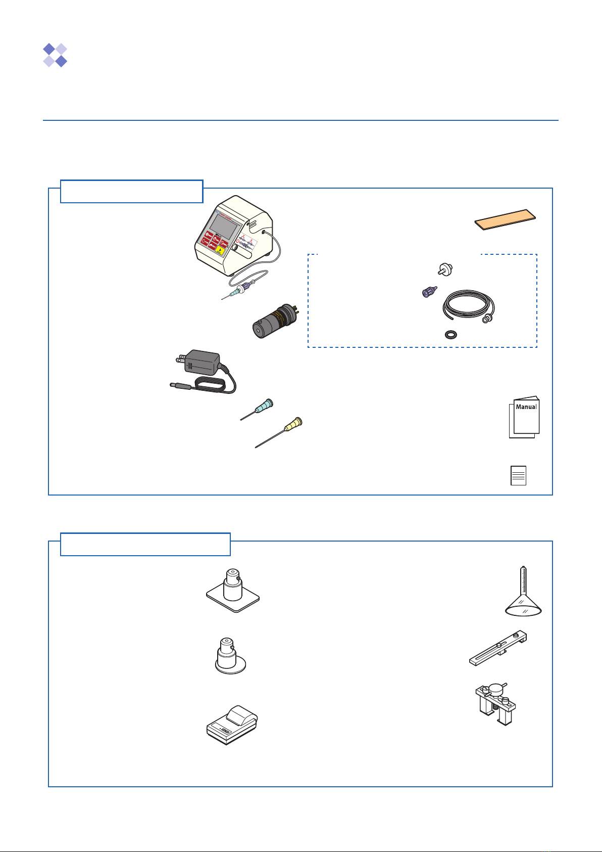
Quick Sampler
(Model: PO-1)
Eliminates the need to attach adhesive
rubber or pierce needle through
adhesive rubber.
Quick Sampler 2
(Model: PO-2)
Suitable when the top of the sample is
indented, such as with a cup.
Printer (printer cable sold separately)
(Model: CBM-910II-40)
Use to print out the measured
values.
-Ordering consumable parts
Printer paper (Model: RP5860) 20-roll set
Ink ribbon (Model: IR91B) 5 ribbon set
Gas sampling glass tube (Model: GS-2)
Use this tube to collect small amounts of
sample gas from the container, such as a
can, bottle, or ampule.
Can opener (Model: KO-1)
Use this opener to measure the remaining
oxygen concentration in a can.
Opener (Model: KO-X1)
Use this opener to measure the remaining
oxygen concentration in a bottle.
Storage case (Model: ROPSC1)
Storage case dedicated for the RO-105
series.
PACK LEADER x 1 unit
Main unit
Sampling adapter
Oxygen sensor (WAGNIT®) x 1 unit
(Model: WA-SGF2)
Already mounted in the main unit housing.
AC adapter x 1 unit
(Model: AC-105)
Needle (vertical slot type) x 2 pcs.
Needle (horizontal slot type) x 1 pc.
Switch the type when measuring a sample, such as
an adhesive, that can easily clog the needle.
Adhesive rubber x 20 pcs.
Size: 20mm x 100mm x t1
Maintenance kit (model: MK-105)
Membrane filter x 3 pcs.
Check valve x 1 pc.
Sampling tube with fitting
(length: 50cm) x 3 pcs.
O-ring for housing x 1 pc.
AA alkaline batteries x 4 pcs.
Already mounted in the main unit.
Operation manual and
warranty (this document) x 1 copy
Handy User’s Guide x 1 copy
Oxygen sensor warranty x 1 copy
Before starting use
2. Conrmationofpackagecontents
When unpacking the PACK LEADER, confirm that the following items are included and that the contents have
not been damaged. If any parts are missing or damaged, contact the dealer from which you purchased the
product.
Package contents
“WAGNIT®” is a registered trademark of the Iijima Electronics Corporation oxygen sensor.
Accessories (options)
Output 6 VDC
* Refer to the instructions enclosed with each product for details on handling.

Spare sensor (unopened)
After one year
使用中センサー
Warranty term
Service life
Service
life
保証期限のお知らせ
30 days
One year
If the sensor fails in 8 months
Approx. 4 months
One year
Spare sensor (unopened)
Replace with new sensor
Replace with
new sensor
Original warranty term
One year
One year
After two years
Sensor package opened
Notice of warranty term
(Recommended to prepare sensor)
Equals remaining warranty term
Malfunction replacement
One year
Sensor package opened
Sensor package opened
Sensor package opened
Oxygen sensor (WAGNIT®)
(Model: WA-SGF2)
Always confirm the information in
“3. Precautions for oxygen sensor”
before purchasing.
AC adapter (Model: AC-105)
Output 6 VDC
Needle (TERUMO NN-2116R-12)
Vertical slot type, 12-pc. set
Needle (Model: T-30-12)
Horizontal slot type, 12-pc. set
Membrane filter (5-pc. set)
(Model: RO-MF)
Adhesive rubber (Model: RG-1)
Size: 20mm x 100mm x t1
100-piece set
Check valve (3-pc. set)
(Model: RO-CV)
Sampling tube with fitting (5-pc. set)
(Model: RO-SC) Length: 50cm
Sampling adapter
(Model: SA-5)
Needle (vertical slot type), membrane filter,
check valve, tube set
Maintenance kit (model: MK-105)
<Contents>
Membrane filter x 3 pcs.
Check valve x 1 pc.
Sampling tube with fitting x 3 pcs.
O-ring for housing x 1 pc.
O-ring for housing (10-pc. set)
(Model: P-8-10)
Main cover (Model: RO-C)
With knurled screws for the main cover
When purchasing consumable parts for new replacements or spare part inventory, please refer to the following
section, and contact the dealer from which you purchased the product.
[Accessories (Consumable parts)]
3. Precautions for oxygen sensor (Model: WA-SGF2)
In principle, the oxygen sensor (WAGNIT®) Model: WA-SGF2 will deteriorate over time and become unusable at
the end of its service life. Please understand and agree to the following precautions before making a purchase.
■WA-SGF2warrantyterm
When the sensor is already mounted in the main unit, the warranty is valid for one year from the date of shipment from Iijima Electronics Corporation.
When purchasing the single sensor unit, the warranty is valid for one year from the date that the sensor package is opened. (Note that the maximum
warranty term is two years, including the storage term*and warranty term.) * "One year storage" is only in the case of using in Japan.
■Warrantydetails
Iijima Electronics Corporation will send a “malfunction replacement” if the sensor becomes unusable due to a malfunction within one year after the
sensor package is opened. (The “malfunction replacement” is not a new part. The usable service life will correspond to the remaining warranty term.)
■Storageterm(OnlyinthecaseofusinginJapan)
Only when this instrument is used in Japan, the oxygen sensor can be stored in an unopened state for up to one year. The sensor can be stored as a
spare sensor, thus preventing missing measurements if the sensor suddenly becomes unusable due to a malfunction.
There is a very slight chemical reaction even during storage. Thus, the sensor should be opened and used within one year. If the sensor is stored for
longer than the maximum storage period of one year, it can still be used, but the warranty term and service life will be reduced by the number of days it
was stored.
<Image of storing one spare sensor and replacing once a year>
The oxygen sensor in the unopened package must be set on its side in the bag and stored in a temperature range of
0 to 30°C. If the storage conditions are not satisfied, the sensor may not operate properly when opened.
Note

Before starting use
1. Safety precautions (Warning, Caution, Note)
2. Confirmation of package contents
Package contents, Accessories (options), Accessories (Consumable parts)
3. Precautions for oxygen sensor (Model: WA-SGF2)
Contents
Names and functions of each part 1
Main unit section
•••••••••••••••••••••••••••••••••••••••••••••••••••••••••••••••••• 1
Housing section /Oxygen sensor (WAGNIT®) /CO2sensor
• • • • • • • • • • • • • • • • • • • • • • • • • • • • • • • 2
Operation Methods
3
1. Preparing for use •••••••••••••••••••••••••••••••••••••••••••••••••••••••
3
Using the PACK LEADER with batteries /Using the PACK LEADER with 100 VAC power
••••••••• 3
2. Preparing for measurement ••••••••••••••••••••••••••••••••••••••••••••••
3
Power ON/OFF
••••••••••••••••••••••••••••••••••••••••••••••••••••••••••••••••••• 3
Switching the measurement mode /Automatic stability decision function /Key Lock / Unlock function • • • • • • • 4
Japanese / English selection function
•••••••••••••••••••••••••••••••••••••••••••••••••• 5
3. Calibration (O2measurement) ••••••••••••••••••••••••••••••••••••••••••••
6
Span calibration
• • • • • • • • • • • • • • • • • • • • • • • • • • • • • • • • • • • • • • • • • • • • • • • • • • • • • • • • • • • • • • • • • • • 6
Zero calibration
••••••••••••••••••••••••••••••••••••••••••••••••••••••••••••••••••• 7
4. Measurement and recording •••••••••••••••••••••••••••••••••••••••••••••
8
Preparing to measure
• • • • • • • • • • • • • • • • • • • • • • • • • • • • • • • • • • • • • • • • • • • • • • • • • • • • • • • • • • • • • • • 8
O2/CO2Measurement (Auto mode) /O2/CO2measurement (Manual mode)
•••••••••••••••••••• 9
Memory function /Confirming the measurement history
•••••••••••••••••••••••••••••••••••10
Erasing the measurement history /Guidance display function [Procedure display]
••••••••••••••11
Various Settings and Functions
12
Setting the O2displays [O2DISP SET]
• • • • • • • • • • • • • • • • • • • • • • • • • • • • • • • • • • • • • • • • • • • • • • • • • • 12
Setting the time [TIME SET]
• • • • • • • • • • • • • • • • • • • • • • • • • • • • • • • • • • • • • • • • • • • • • • • • • • • • • • • • • • 13
Time zone selection function [TIMEZONE]
• • • • • • • • • • • • • • • • • • • • • • • • • • • • • • • • • • • • • • • • • • • • • • • 14
Output setting [OUT SET]
•••••••••••••••••••••••••••••••••••••••••••••••••••••••••••15
Checking for clogging [CLOG CHECK]
•••••••••••••••••••••••••••••••••••••••••••••••••16
Initialization [INITIALIZE]
••••••••••••••••••••••••••••••••••••••••••••••••••••••••••••18
Erasing the entire history [CLR ALL HST]
• • • • • • • • • • • • • • • • • • • • • • • • • • • • • • • • • • • • • • • • • • • • • • • • 19
CO2functions and settings •••••••••••••••••••••••••••••••••••••••••••••••••
20
Disabling the CO2display [CO2OFF]
• • • • • • • • • • • • • • • • • • • • • • • • • • • • • • • • • • • • • • • • • • • • • • • • • • • 20
Upper limit setting [UP LIMIT SET]
•••••••••••••••••••••••••••••••••••••••••••••••••••••21
CO2Calibration [CO2CAL]
• • • • • • • • • • • • • • • • • • • • • • • • • • • • • • • • • • • • • • • • • • • • • • • • • • • • • • • • • • • 23
Connecting to an external device (Serial communication)
25
Connecting a printer /Connecting to a personal computer
•••••••••••••••••••••••••••••••••25
Maintenance
26
Replacing the oxygen sensor /Replacing the CO2sensor /Replacing the needle
••••••••••••26
Replacing the membrane filter /Replacing the check valve
• • • • • • • • • • • • • • • • • • • • • • • • • • • • • • • • 27
Replacing the sampling tube with fitting
•••••••••••••••••••••••••••••••••••••••••••••••••27
Troubleshooting
28
Troubleshooting • • • • • • • • • • • • • • • • • • • • • • • • • • • • • • • • • • • • • • • • • • • • • • • • • • • • • • • • • • •28
Displaying the product information
•••••••••••••••••••••••••••••••••••••••••••••••••••••28
Error Messages •••••••••••••••••••••••••••••••••••••••••••••••••••••••••••
32
Product Specifications
36
After Sales Service
37
1
-
+-
+
+
-+
-
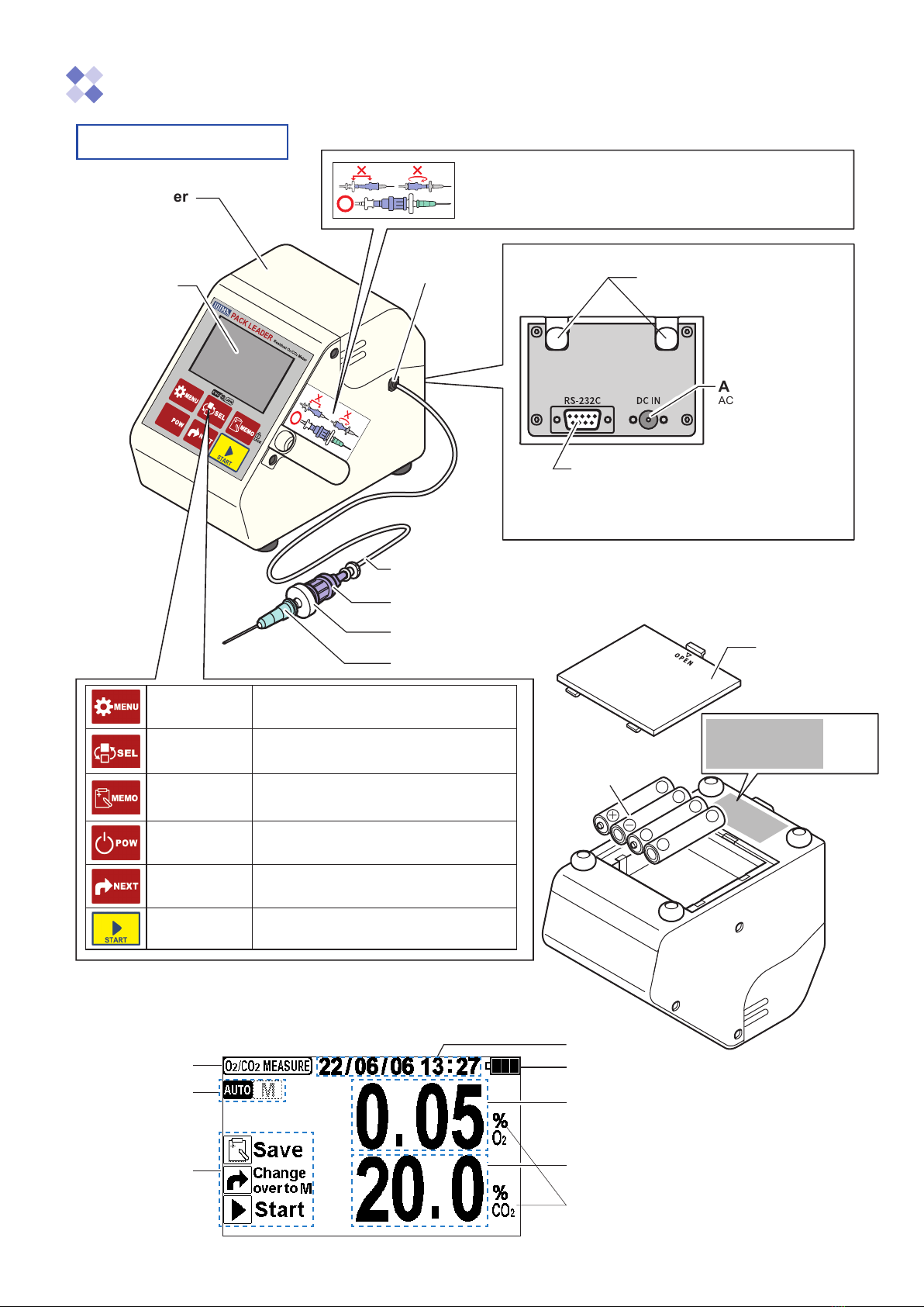
Names and functions of each part
Main unit section
LCD display area
Displays measured value, etc.
Measurement
mode
Title
(The following example shows the Measurement Complete screen.)
Operation guide
display
Membrane filter
Needle
Battery level
Date / time
Unit
Check valve
Knurled screws for the main cover
Remove the main cover when replacing
the oxygen sensor.
AC adapter jack
AC adapter connection
Serial communication connector
• Connection with a printer (optional) (for printing the
measured values)
• Connection with a personal computer (for retrieving the
measured values; operating the main unit)
Tube fitting
Main cover
<Back side>
<Base> Battery box
<LCD display area>
Battery
cover
AA alkaline
battery x 4
MENU key Press to display the menu or return to the
previous screen
SELECT key
Press to switch to the measurement history
Hold for 3 seconds to switch displayed language
between Japanese and English
MEMORY key
Press to save a measured value or delete a
measured value
Hold for 3 seconds to lock or unlock operations
POWER key Press to turn the power ON or OFF
NEXT key Press to switch the measurement mode or
selection
START key Press to start the measurement, start calibra-
tion, enter a selection, or stop operation
O2measurement
value
CO2measurement
value
Sampling tube with fitting
Product name
Model
Serial number
Manufacturng
date
The correct order and direction for connecting the
sampling adaptor are indicated with a sticker.
When operating or storing the unit, refer to this sticker and confirm that the
sampling adaptor is correctly connected.
Product name :Residual O2/CO2 Meter
Model : RO-105LS
Serial number : *******
Manufacturing date :
20**.**

2
Oxygen Sensor WAGNIT®
Model:WA-SGF2 Serial number:130****
Iijima Electronics Corp.
Housing section
Oxygen sensor
CO
2
sensor
The CO2sensor (model: CS-105) is built into the PACK LEADER unit and cannot be removed or mounted
by the customer.
When the CO2sensor has reached its life, please send the PACK LEADER unit set to the dealer from
which you purchased.
Oxygen sensor (WAGNIT®)
(Model: WA-SGF2)
The front center
section has a metal
mesh.
Product name
Model Serial No.
Probe
Probe cable
Housing
O-ring for
housing
Oxygen sensor
CO2sensor (already mounted inside)
3
Operation Methods
1. Preparing for use
Using the PACK LEADER with batteries
The batteries are mounted before shipment, so the PACK LEADER can be used right away.
When replacing the batteries, use AA alkaline batteries or nickel-metal hydride batteries (ENELOOP).
Using the PACK LEADER with 100 VAC power
Always use the enclosed AC adapter.
•Always remove the batteries when using the AC adapter or when suspending the use of the
instrument for a long time and putting the unit into storage. The instrument could be damaged
if the battery fluid leaks.
•Always use the enclosed AC adapter. Failure to do so could damage the instrument.
2. Preparing for measurement
Power ON/OFF * After turning the power OFF, wait at least two seconds before turning it ON again.
•The calibration or measured value could be affected if the ambient temperature changes. In
this case, turn the power OFF with the oxygen sensor set, and wait at least 30 minutes for
the temperature to stabilize.
•Always remove the tip of the needle from the sample before turning the power OFF.
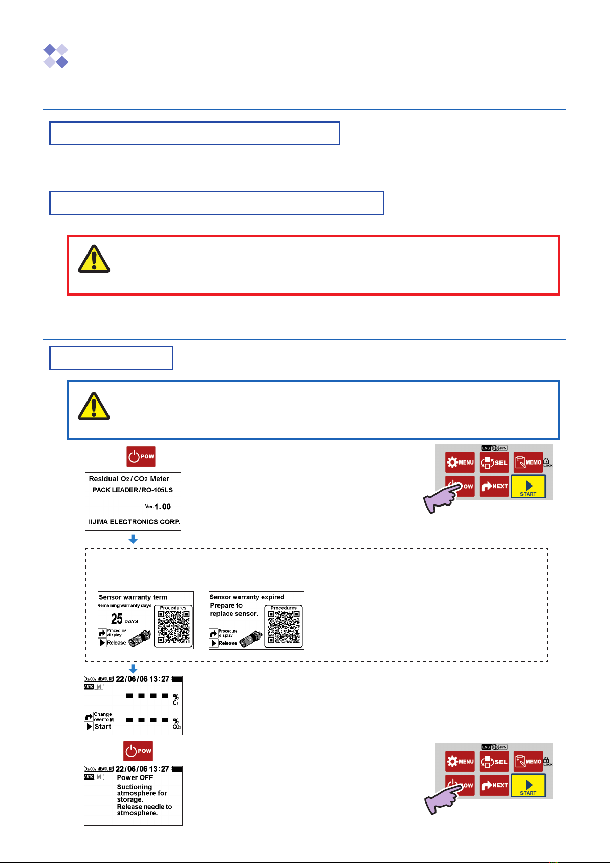
1. Press .
The power turns ON, and the software version displays.
(Approx. 4 seconds)
* The displayed details will vary according to the version.
The Measurement Standby screen opens.
* The screen on the left shows the Auto mode and Concentration
% O2setting.
2. Press again.
The atmosphere is automatically suctioned. After the
screen on the left opens, the power turns OFF.
Sensor warranty term notification function (Displayed when the self-diagnosis function determines that
there are 30 days or less to the end of the oxygen sensor warranty term.)
Display when 25 days are remaining Display when 0 days are remaining (end of warranty term)
* The warranty is valid for one year from the date of shipment.
(When the sensor is replaced, one year from the date the new sensor
package is opened.)
* The display on the left is a guideline.
The self-diagnosis results are also displayed.
Caution
Note
4
Automatic stability decision function When taking a measurement, the indication value at the
most stable state is automatically held.
The timing for deciding the stability is different for the
Auto mode and Manual mode.
Press .
The measurement starts, and the Stability Decision screen opens.
The decision is completed when a beep sounds and the stabilized measured value appears.
<Manual mode>
Hold down and suction the gas.
The pump operates only while the key is held down, and the stability decision starts when the key is released.
The decision is completed when a beep sounds and the stabilized measured value appears.
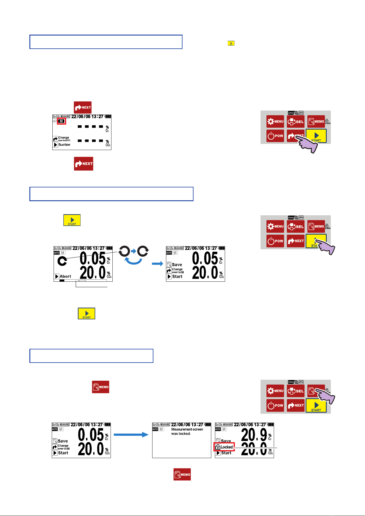
Key Lock / Unlock function Lock the keys to prevent operations other than measurement and history
display. Use this function to prevent accidental setting changes, calibration,
measured value switching, or history erasing. Until the keys are unlocked,
the locked state is retained even if the power is turned OFF, the batteries are
removed, or the AC adapter is disconnected.
1. Hold down for 3 seconds or longer on the
O
2
/CO
2
MEASURE Screen.
“Locked” displays.
The key lock function is enabled while “Locked” is displayed.
2. Unlock the lock function by pressing again for 3 seconds or longer.
The “Locked” display disappears.
Switching the measurement mode The mode is set to Auto as the default when the unit is
shipped. When is pressed in the Auto mode, the cycle of
operations from pump and suction of sample gas, automatic
stability decision, and holding of indicated value is completed
automatically.
The Auto mode is usually used. Measurements can be taken in the Manual mode in the following cases.
• When the contents are visible through the packaging, and you want to suction the gas while adjusting the tip of the
needle so that it does not pierce the contents.
• When sampling approx. 6 mL of gas using the optional “Gas sampling glass tube (model: GS-2)” and you want to
suction the gas while adjusting the needle so that the liquid is not suctioned.
1. Press .
The mode switches to the Manual mode.
“M” (MANUAL) is selected.
2. Press .
The mode returns to the Auto mode.
<Auto mode>
Progress status bar display
“Locked” display
Hold down for
3 seconds or
longer

5
Japanese/Englishselectionfunction Japaneseisthefactorydefaultsettingforthedisplay.The
displayedlanguagecanbeswitchedbetweenJapanese
and English from any screen.
Usually, the language can be switched between Japanese and English from any screen if the power is ON. Note that the
language cannot be switched during the following operations. The language can be switched once the operation is fin-
ished or canceled and the built-in pump has stopped.
• During O2/CO2measurement operation
• During calibration (span calibration/zero calibration) operation
• During the clogging check operation
1. With the power turned ON, hold down the for 3 seconds
or longer.
The display language will switch from Japanese to English.
(The displayed contents are saved.)
Hold down for
3 seconds or
longer
JapaneseEnglish
2. When the is held down again for 3 seconds or longer, the language will return to
Japanese.
<WhenusingincountriesorregionsotherthanJapan>
By using the “Time zone selection function,” the time zone can be set to the standard of the region
where the instrument is being used.
Refer to “Time zone selection function” on page 14 for the operation methods.
6
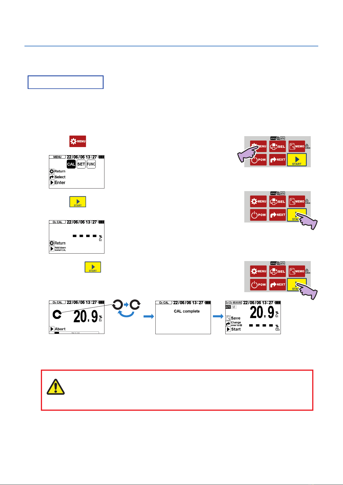
3. Calibration (O2measurement)
The calibration process adjusts the instrument measured value so that the span point and zero point during O2
measurement match the sensor output when the reference gases (atmosphere, nitrogen) were measured.
Span calibration Perform span calibration once a day before starting measurements. Ideally, span calibration
should be performed when the temperature of the oxygen sensor and temperature sensor
are sufficiently stable, such as first thing in the morning before operating the air conditioning
system.
If the deviation from the true value can be tolerated by about 5%, span calibration should be performed when the
oxygen concentration in the atmosphere is 20% O2or less, or 22% O2or more. In this case, the error will be
0.05% O2when the measurement concentration is 1% O2.
1. Place the needle in the atmosphere.
2. Press .
The MENU screen opens, and “CAL” is selected (flashes).
3. Press .
The O2CAL screen opens.
* If even one measurement has been taken, the previous measured value will display.
4. Hold down for 1 second or more.
The calibration starts, and the Stability Decision screen opens.
A beep sounds, CAL complete appears (approx. 1 second), and then the O2/CO2
MEASURE screen opens. The calibration process is completed.
The calibration value is saved even if the power is turned OFF, the batteries are removed, or the AC adapter is
disconnected.
If the “Sensor error” message appears, refer to the section “Error Messages” (pages 32 ) and confirm and remedy
the situation.
The measured value (calibration value) may be high or low if a strong impact is applied on
the instrument unit or if the temperature changes drastically. In this case, wait for some time
and then perform span calibration again.
Caution

7
Zero calibration To accurately measure low concentrations when measuring O2, use nitrogen gas for calibration.
1. Set the needle so it can suction the nitrogen gas.
2. Press .
The MENU screen opens, and “CAL” is selected (flashes).
3. Press .
The O2CAL screen opens.
* If even one measurement has been taken, the previous measured value will display.
4. Hold down for 1 second or more.
The calibration starts, and the Stability Decision screen opens.
A beep sounds, CAL complete appears (approx. 1 second), and then the O2/CO2
MEASURE screen opens. The calibration process is completed.
The calibration value is saved even if the power is turned OFF, the batteries are removed, or the AC adapter is
disconnected.
If the “Sensor error” message appears, refer to the section “Error Messages” (page 32 ) and confirm and remedy
the situation.
The measured value (calibration value) may be high or low if a strong impact is applied on the
instrument unit or if the temperature changes drastically. In this case, wait for some time and
then perform zero calibration again.
<When nitrogen gas cannot be prepared>
Initialize the instrument and then perform span calibration.
Refer to the sections “Initialization” (page 18 ) and “Span calibration” (page 6 ) for details on the operation meth-
ods.
Caution

8
Adhesive
rubber
4. Measurement and recording
Preparing to measure
•It may not be possible to measure if the sample gas quantity is less than 10mL.
•A measurement can be taken even if the inside of the sample is depressurized, but if the
package’s internal pressure is less than -30kPa, a correct measurement value may not be
obtained. Note that depressurization will occur easily after gas suction, especially if the gas
quantity is low. In this case, a measurement can be taken using the optional “gas sampling
glass tube (model: GS-2)”.
•The measurement may take longer if the inside of the sample is depressurized.
•A measurement can be taken even if the inside of the sample is pressurized. However, if
the package’s internal pressure is higher than +40kPa, the components could break when
the needle is pierced, or a correct measured value may not be obtained. In this case, a
measurement can be taken using the optional “gas sampling glass tube (model: GS-2)”.
1. Shift the contents in the pack to one side and hold with a
hand to create a space for piercing the needle.
2. Attach the enclosed adhesive rubber over the air space.
Adhesive rubber cutting dimension reference: 1cm x 1 cm square
3. Lightly press down on one side of the bag, and set the
needle in the sample gas.
Do not suction the contents.
A measurement error will occur if powder, etc., gets clogged in the needle.
Note that the minute amount of liquid in the sample gas is blocked by the membrane filter.
Warning
Take care not to stab the human body with the needle. There is a risk of blindness, puncture
wounds, or cuts.
•If pressure is applied into the pack from the set needle using an air gun, etc., the internal
pump or sensor could be damaged. If the needle is clogged, replace it with a new needle.
•Continuing use with a clogged needle, membrane filter, check valve, or sampling tube with
fitting will deteriorate the sensor.
•If the liquid is accidentally suctioned, the membrane filter that has absorbed the liquid will not
pass the gas, preventing a correct measurement. Note that if the liquid contains oil, it might
pass through the membrane filter. Refer to “Maintenance” (pages 26 to 27) and replace
the needle, membrane filter, check valve, and sampling tube with fitting contaminated with
liquid or oil with new parts. Check the housing to confirm that the suctioned liquid and oil
have not adhered to the oxygen sensor. If adhered, remove the oxygen sensor and clean
the inside of the housing. The metal mesh at the front center of the oxygen sensor can be
cleaned by lightly wiping with tissue paper.
• Using the needle, membrane filter, check valve, and sampling tube with fitting in a clogged
state may prevent a correct measurement.
Caution
Note
Note

9
O2/CO2Measurement (Auto mode) The measurement starts automatically when is pressed.
Refer to the section “Switching the measurement mode” (page
4 ) for details on switching between the auto mode and
manual mode.
1. When the Measurement Standby screen is displayed, press .
The measurement starts, and the Stability Decision screen opens.
The decision is completed when a beep sounds and the stabilized measured value
appears.
• If the “Sensor error”, “Sensor unstable”, or “Negative pressure detected” message appears, refer to the section “Error
Messages” (page 32) and confirm and remedy the situation.
• To stop the measurement while deciding the stability, press . The measurement will be aborted.
2. To record the measured value, press on the Measurement
Complete screen.
The measured value is saved in the main unit.
Refer to section "Memory function" (page 10 ) for details.
The value indicated when is not lit is read.
O2/CO2measurement (Manual mode)
1. If the Manual mode is not enabled, press .
This step is not required if the Manual mode is enabled.
The selected measurement mode is saved even when the power is turned OFF.
<Auto mode> <Manual mode>
2. With the Measurement Standby screen displayed, hold down (Suction).
The pump operates only while is held down.
In the manual mode, the stability decision is canceled while the pump is operating.
The stability decision starts when the key is released, and the pump stops.
(If the measurement value fluctuates, the Stability Decision screen will appear.)
The decision is completed when a beep sounds and the stabilized measured value appears.
The value indicated when is not lit is read.
3. To record the measured value, press on the Measurement Complete screen.
The measured value is saved in the main unit.
Refer to section "Memory function" (page 10 ) for details.
The pump operates only while is held down. Refer
to the section “Switching the measurement mode” (page
4 ) for details on switching between the auto mode
and manual mode.
10
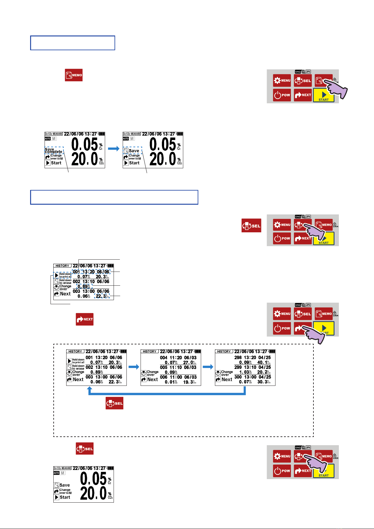
Memory function The measured value is not automatically saved in the internal memory. Using the
following steps, up to 300 values can be saved and retained in the internal memory.
When 300 values are exceeded, the oldest data is automatically deleted.
Press on the Measurement Complete screen.
The measured value for which the stability has been automatically decided is saved.
“Save complete” appears, and the current date and time, O2measurement value, and
CO2measurement value are saved.
(Note that if CO2OFF is selected, the CO2value is not saved.)
The saved details are retained even if the power is turned OFF, the batteries are removed, or the AC adapter is
disconnected.
Displays for approx. 1 sec. Returns to normal display
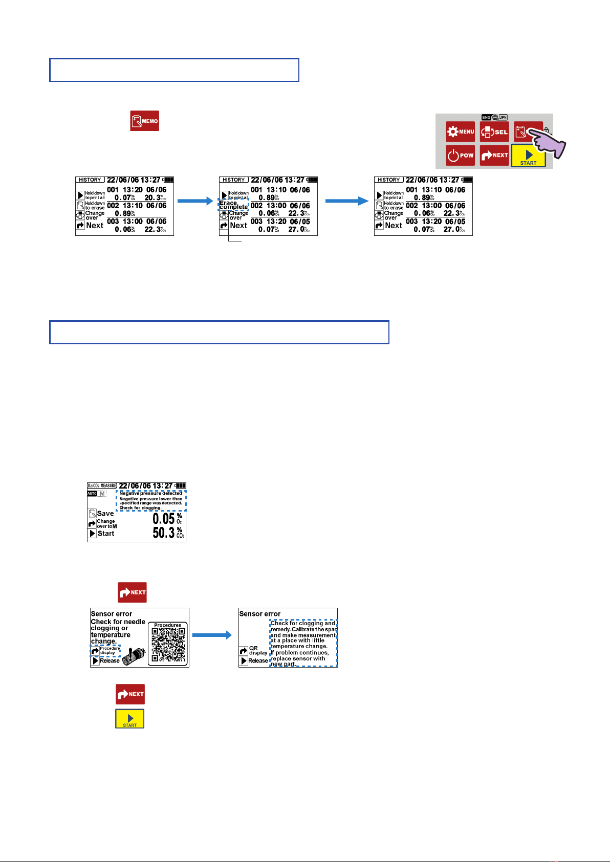
Conrmingthemeasurementhistory The saved measured values can be displayed and confirmed
later. Note that if CO2OFF is selected, the CO2measurement
value is not displayed.
1. When the Measurement Standby screen is displayed, press .
The HISTORY screen opens.
Immediately after the screen switches, three measurements with the latest date and time are displayed.
2. When is pressed, the older data is displayed three items
at a time.
When the key is held down, the page will switch.
* Press twice to return to the latest history page.
• Up to 300 measurements are saved.
• When 300 measurements are exceeded, the oldest is deleted, and the newest is saved.
3. Press .
The O2/CO2MEASURE screen opens.
CO2measurement value
O2measurement value
(Displayed only when printer output is set)
No. (displayed by latest date and time)
Saved time and date
11
Guidance display function [Procedure display] This function displays and guides the
remedy procedures for malfunctions or
error messages that may occur during use.
If an error message appears, the screen will switch to the one showing the procedures to be taken
depending on the displayed details.
(Some guidance displays do not require switching to the procedure display.)
Follow the instructions on the screen to remedy the error.
<Example 1> When “Negative pressure detected” is displayed
As a remedy, perform a clogging check (refer to page 16 ).
<Example 2> When “Sensor error” is displayed
Press (procedure display). The remedy procedure will display.
When (QR display) is pressed again, the screen returns to the Error Message screen.
Press to cancel the display.
Hold
down for
1 second
or longer
Erasing the measurement history The latest measurement value records can be deleted one item at
a time.
Use this when a measurement value has been accidentally saved.
Hold down for 1 seconds or longer on the HISTORY Screen.
“Erase Complete” displays for approx. one second, and then contents of the data saved
last are erased from the internal memory.
The display returns to the HISTORY screen.
“Erase complete” displays Returns to HISTORY screen
To erase the entire history, refer to the section “Erasing the entire history” (page 19 ).
Procedure
display
As a remedy, perform a clogging check (refer to
page 16 ) or span calibration (refer to page 6 ).

12
Various Settings and Functions
Setting the O2displays [O2DISP SET] The display method can be changed to display the O2
measurement value as gas replacement rate. However, even
if the display is changed to the replacement rate % display,
the CO2measurement value will not change from the
concentration display to the replacement rate display.
Gas replacement rate (%) = (1 – Oxygen concentration (%O2) )×100
20.9
1. When the Measurement Standby screen is displayed, press .
The MENU screen opens.
Immediately after opening, “CAL” is selected (flashes).
2. Press .
The cursor moves, and “SET” is selected (flashes).
3. Press .
The SETTING MENU screen opens.
Immediately after opening, “O2DISP SET” is selected
(flashes).
4. Press .
The O2DISP SET screen opens.
“CONCN% O2” (currently set O2display) is selected
(flashes).
5. Press .
The cursor moves, and “REP-R%” is selected (flashes).
6. Press .
The setting change screen displays for approx. 1 second, completing the changes to
the settings.
(The screen returns to the SETTING MENU screen.)
13
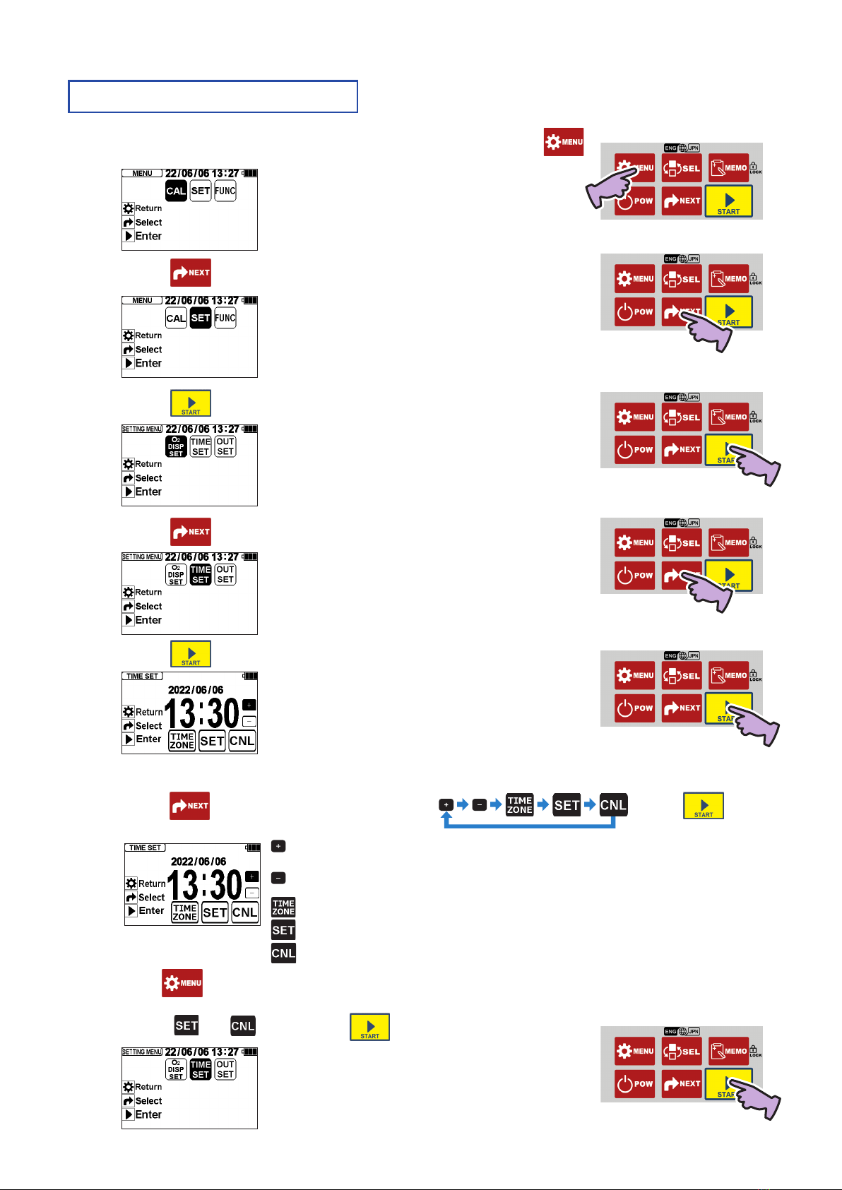
Setting the time [TIME SET] Set the time if the displayed time has deviated.
1. When the Measurement Standby screen is displayed, press .
The MENU screen opens.
Immediately after opening, “CAL” is selected (flashes).
2. Press .
The cursor moves, and “SET” is selected (flashes).
3. Press .
The SETTING MENU screen opens.
Immediately after opening, “O2DISP SET” is selected
(flashes).
4. Press .
The cursor moves, and “TIME SET” is selected (flashes).
5. Press .
The TIME SET screen opens.
Immediately after opening, “+” is selected (flashes).
* The example on the left shows the current date as 2022
June 6 and the time as 13:30.
6. Change the time with the following steps.
Press . The cursor will move in the order of
. When is
pressed, the cursor function will activate.
... The time is advanced by one minute.
* Hold down the key to advance the time 10 minutes in 0.5-second increments.
... The time is returned by one minute.
* Hold down the key to return the time 10 minutes in 0.5-second increments.
... The internal clock can be changed to the local standard time (refer to page 14 ).
... The displayed time is set, and the SETTING MENU screen opens.
... The time changes are canceled, and the SETTING MENU screen opens.
When is pressed, the time changes are aborted, and the SETTING MENU opens.
7. Select or , and press .
The time setting is completed or canceled, and the screen
returns to the SETTING MENU.

14
Time zone selection function [TIMEZONE] When using the instrument in a country or region
otherthanJapan,theinstrument’sinternalclock
can be changed to the local UTC (coordinated
universal time).
A time zone is a geographical region that uses the same standard time. The deviation from the UTC
(coordinated universal time) is expressed with a positive or negative sign, such as “UTC+9:00”.
Japan’sdesignatedstandardtimeis“UTC+9”,sothefactorydefaultsettingis“UTC+9:00”.
1. Refer to the section “Setting the time” on page 13 and proceed with steps 1 to 5.
The “TIME SET” screen opens.
Immediately after opening, “+” is selected (flashes).
2. Press twice.
The cursor moves, and “TIMEZONE” is selected (flashes).
3. Press .
The “TIME SET” screen opens.
Immediately after opening,
“+” is selected (flashes).
4. Change the time zone with the following steps.
Press . The cursor will move in the order of
. When is
pressed, the cursor function will activate.
... The displayed UTC is advanced by one unit.
... The displayed UTC is returned by one unit.
...Thetimezoneisreturned(initialized)toJapan'stimezone"UTC+9:00".
... The displayed UTC is set, and the TIME SET screen opens.
... The time zone selection is canceled, and the TIME SET screen opens.
5. Select , and press .
The internal time is changed to the selected time zone,
and the TIME SET screen opens.
* The display on the left shows the time after changing to
"UTC+6:00".
6. Press . The SETTING MENU opens.
The time zone selection is completed and the screen
returns to the SETTING MENU.
Table of contents
Other Iijima Measuring Instrument manuals


