ENERAC 500 User manual

INSTRUCTION MANUAL
MICRO-EMISSIONS ANALYZER
MODEL 500
ENERAC, INC.
67 BOND STREET
WESTBURY, NY 11590
(800) 695-3637
FAX (516) 997-2129
Revision 3.0

1

2
LIST OF ABBREVIATIONS....................................................................................3
OPTIONS...................................................................................................................4
CHAPTER 1
FUNDAMENTALS ...................................................................................................6
CHAPTER 2
THE INSTRUMENT KEYBOARD..........................................................................9
CHAPTER 3
BASIC INSTRUMENT OPERATION ...................................................................11
THE SMOKE TEST.............................................................................................14
CHAPTER 4
ANALYZER DESCRIPTION .................................................................................15
A. POWER REQUIREMENTS .........................................................................15
B. SAMPLE FLOW DESCRIPTION ................................................................16
C. THERMOELECTRICALLY COOLED CONDENSATION TRAP ...........17
D. SENSORS DESCRIPTION...........................................................................20
CHAPTER 5
ANALYZER SETUP...............................................................................................23
A. SYSTEM MENU...........................................................................................23
B. SPAN MENU ................................................................................................26
C. STORAGE MENU ........................................................................................27
D. PRINTER SETUP MENU.............................................................................28
E. SENSOR SETUP MENU..............................................................................29
CHAPTER 6
COMMUNICATIONS ............................................................................................30
A. ENERCOM SOFTWARE .............................................................................30
B. SERIAL COMMANDS.................................................................................33
THE ENERAC 500 COMMAND SET................................................................34
CHAPTER 7
CALIBRATION.......................................................................................................37
A. AUTOZEROING THE INSTRUMENT.......................................................37
B. SPAN CALIBRATION .................................................................................38
CHAPTER 8
MAINTENANCE ....................................................................................................43
APPENDIX A
MODEL 500 SPECIFICATIONS............................................................................48
APPENDIX B
FIRMWARE PROGRAMMING.............................................................................52
APPENDIX C
REPLACMENT PARTS .........................................................................................53

3
LIST OF ABBREVIATIONS
PARAMETERS
AMB T Ambient (room) temperature
CO Carbon monoxide (a toxic gas)
CO2 Carbon dioxide
COMBUST Combustible gases
EFFIC Combustion efficiency (for boilers and furnaces, does not
apply to engines)
EX AIR Excess air
NO Nitric oxide (a toxic gas)
NO2 Nitrogen dioxide (a toxic gas)
NOX Oxides of nitrogen (a toxic mixture of nitric oxide and
nitrogen dioxide gases)
OXYGEN REF Oxygen reference basis for correction of toxic gas
Concentration
SO2 Sulfur dioxide (a toxic gas)
STACK T Stack temperature
THERMAL EFF Engine thermal efficiency (heat loss method of
calculation, not the same as combustion efficiency)
UNITS
PPM Parts (of pollutant) per million (volume basis-dry)
MGM Milligrams (of pollutant) per cubic meter
GBH Grams (of pollutant) per (engine) brake horsepower-hour
#/B Lbs. (of pollutant) per million BTU (of fuel)
" Inches of water (draft measurement)
% Percent by volume dry basis

4
OPTIONS
The ENERAC Model 500 has been designed as a modular system, permitting the
installation in the field of most of the various available options. This manual
describes the complete instruments equipped with all the options. The available
options on the Model 500 are as follows:
a. 2" ENERAC Printer.
b. Nitric oxide (NO) measurement capability.
c. Nitrogen dioxide (NO2) measurement capability.
d. Sulfur dioxide (SO2) measurement capability.
e. Combustible gas measurement capability.
f. Stack draft measurement capability.
g. Smoke test (ASTM method D2156) capability.
h. Bluetooth wireless communication option.
i. Thermoelectric cooler option (Peltier drier).
j. Extra-long 36" or 48" inconel probe option.
k. Emissions units option (Lbs / millionBTU & Grams / brake-HP-hour).
l. Custom fuel option. (Either at the factory, or programmable using the
ENERCOMTM for WINDOWSTM option.
m. CD-ROM with custom software:
• EnercomTM for WINDOWSTM95/98/ME/NT/XP,
• EnercomCE for WINDOWS CE (Pocket PC),
• EnerPalm for PALM OS.
Any combination of these options are available to meet the customer's
requirements.

5
Various cables and attachments are available for special connections to the Micro
Emissions Analyzer.
In addition, high resolution 0-200 PPM and extended range 0-4000 PPM versions
are available on request. (For carbon monoxide only, 0-10,000 PPM and 0-20,000
PPM ranges are also available).

6
CHAPTER 1
FUNDAMENTALS
The ENERAC Model 500 Micro Emissions Analyzers are hand held state of the art
analyzers designed for the following tasks:
•To measure the emissions of carbon monoxide, oxides of nitrogen, sulfur
dioxide and oxygen from stationary and mobile combustion sources.
•To assist the operator of a combustion source with the task of optimizing its
performance and saving fuel.
•To be used as a management tool to assist the plant manager with keeping
records and controlling costs.
The ENERAC Model 500s are easy to carry and utilize the latest technology;
reliable flue type electrochemical sensors manufactured by the largest sensor
manufacturer to measure emissions.
The ENERAC use sophisticated electronics and programming designed for
increased accuracy and flexibility. It measures 2 temperatures and 5 different stack
gases. It computes efficiency of combustion, as well as excess air and carbon
dioxide. It communicates with a variety of other computers via its serial ports. It
has a library of 15 fuels, diagnostic/help messages, and can operate either on its
rechargeable batteries, AC power, or from a set of four AA alkaline cells.
ENERAC has years of experience in the manufacture and marketing of portable
combustion and emission analyzers. The Model 500 is based on this experience,
together with the latest innovations in electronic and sensor technology. They also
express our basic conviction that communications and artificial intelligence are the
basic ingredients of the instrument of the future.
The instrument operates basically as follows:
Connect the probe and water trap to the analyzer. Turn the unit on and then insert
the probe in the stack of an operating combustion source such as a boiler, furnace
or combustion engine. A pump located inside the instrument draws a small sample
of the stack gas. The sample is conditioned before entering the analyzer by passing

7
through a condensation trap and particulate filter. A number of sensors analyze the
contents of the stack gas and its temperature and calculate and display the results.
The results can also be printed, stored or sent to a computer. The source operator
makes the required adjustments based on the analysis of the stack conditions to
optimize performance.
A. UNPACKING THE INSTRUMENT
Every ENERAC Model 500 includes as standard equipment:
1. One Emissions Analyzer Model 500.
2. One stack probe with 10 ft. Viton hose (non-adsorbent, flexible).
3. One condensation trap with filter.
4. One disposable fiber filter.
5. One wall-mounted AC battery charger.
6. One instruction manual.
Every ENERAC sold has stored in its memory information regarding
manufacturing and sensor dates, as well as product identification, serial number of
unit, version and original customer.
B. IMPORTANT ADVICE
Most stack gases are hot, full of moisture, corrosive and laden with soot particles.
To make sure that your instrument will give you a long time of trouble-free
performance, please observe the following recommendations.
1. Follow the instructions in your manual.
2. Never use the instrument without the fiber filter located inside the water
trap. Operating the instrument without the filter will damage the pump and
sensors. (This is a costly replacement!)
3. Do not expose the probe tip to open flame.

8
4. Do not rest the stack probe’s hose on a hot boiler surface.
5. Allow the probe tip to cool off and the instrument aspirate air before packing
the probe.
6. Always be sure to use single-gas blends when calibrating the sensors.
7. Charge the battery at least every two weeks to maintain proper bias on the
sensors.

9
CHAPTER 2
THE INSTRUMENT KEYBOARD
The Model 500 can be operated by using either:
•The 12 button keyboard located on the face of the analyzer, or
•By the use of commands through its serial port, USB port or Bluetooth
interface.
A brief explanation of the instrument’s buttons follows.
ON/OFF Turns the instrument on or off.
PUMP Toggles the instrument’s sample pump on or off. If you hold it
down for 3 seconds it will start a smoke test.
LIGHT Toggles the LCD display’s backlight illumination on or off.
DATA Toggles four LCD display screens. Each screen presents an
instantaneous group of data of four measurement or computation
parameters. The fourth screen displays all parameters
simultaneously. This is the most often used button.
ZERO Executes an instrument autozero (sets oxygen to 20.9%).
STORE This button is used to store data in the instrument’s internal buffers.
STATUS Toggles three LCD screens. The first screen displays the customer
name, time, and date. The second screen displays the current
PUMP LIGHT DISPLAY
DATA
ZERO STORE STATUS PRINT
SHIFT ENTER
ON/OFF

10
software version, unit serial number, battery voltage and selected
fuel. The third screen displays the ambient temperature, units of
temperature, emission units, and selected oxygen reference.
PRINT Sends data to the printer.
The buttons of the last row are used to customize the analyzer and execute all
changes in stored parameters, such as time, fuel, calibration data, etc.
SHIFT Displays the Setup Menu.
▲Increments the entry marked by the cursor to the next higher entry.
(This may be a digit or another parameter).
▼Decrements the entry marked by the cursor to the next lower entry.
(This may be a digit or another parameter).
ENTER Executes and stores all the changes.

11
CHAPTER 3
BASIC INSTRUMENT OPERATION
It is possible to master the basic operation of the instrument in a few minutes by
following the procedure outlined below. Please refer to the other sections of this
manual for a description of the more advanced features.
The Model 500 micro-emissions analyzers consist of two major components, the
probe (whose function is to extract, clean, and dry the sample) and the main unit,
which does the stack analysis and computations.
To operate the instrument follow the steps outlined below.
1. Remove the instrument from its case, attach the sampling probe and water
trap or thermoelectric cooler to the analyzer section, and press the ON/OFF
button.
2. The instrument pump will immediately turn on. If it does not, check the
batteries. If you are using rechargeable batteries, plug in the AC charger. If
the unit will not respond, reset the unit. To reset the unit, press the reset
switch, located on the left side of the unit next to the USB port.
3. Press the STATUS button to obtain information about the analyzer as shown
below by the three screens displayed by toggling the STATUS button:
The first screen shows the model name, customer name, current time & date.
The second screen displays the firmware version of the unit, serial number of the
unit, current battery voltage, and currently selected fuel. The third screen shows the
current ambient temperature, units of temperature and emission measurement, and
the oxygen reference. The selected fuel affects the efficiency and CO2calculations.
The selected oxygen reference affects the CO, NO, NO2, & SO2measurements in
PPM or MGM mode. The fuel and oxygen reference, as well as the time, date, and
measurement units can be changed using the SHIFT menu as described in
STATUS
SCREEN 1
ENERAC M500
Company Name
Time: 12:00:00
Date: 01/01/01
STATUS SCREEN 2
Version: 5.0+
Serial #: 12345
Battery: 5.65 V
Fuel: #2 OIL
STATUS SCREEN 3
Amb Temp 80 F
Temper. Units:F
Meas. Units:PPM
Oxygen Ref:TRUE

12
CHAPTER 5: ANALYZER CUSTOMIZATION. It is a good idea to use the
STATUS button to check the battery voltage before you begin a test. The unit will
display a warning and shut down when the battery voltage drops to 4.0 volts.
4. If the instrument temperature is below 40°F. Allow a few minutes for the
unit to warm up.
5. With the probe connected to the unit, the probe tip at room temperature, and
the instrument aspirating clean air, press the ZERO button to execute an
AUTOZERO.
6. If at the end of the autozero period there are no warning or error messages,
insert the probe into the stack. Wait approximately two minutes before
taking data.
7. Press the DATA button to display the first group of measurements. By
depressing this button again you display the second group of data, and by
depressing it again you will display the third group of data. The data are
grouped as follows:
Toggle the DATA button to view the measurement data in sequence.
NOTE: Depending on the options enabled for your analyzer some of the entries
in one or more of the displays shown above will display “N.A.” if that option is
not available. When the O2level is above 20% the efficiency will read “OVER”.
8. If you want a printed record of the current data, press the PRINT button on
the analyzer. You will get a complete printout of all data, including time and
date, fuel and customer information.
DATA SCREEN 4
OX: 5.8 DFT: 5.5
ST: 460 CMB: 3.0
CO: 146 NO2: 126
NO: 37 SO2: 250
DATA SCREEN
2
CO2: 7.8 %
Ex.Air: 35.0 %
Combust: 3.0 %
Draft: 5.5 "
DATA SCREEN 3
NOX: 163 PPM
NO: 37 PPM
NO2: 126 PPM
SO2: 250 PPM
DATA SCREEN 1
Effic: 85.7 %
Oxygen: 5.8 %
CO: 146 PPM
Stack T: 460 F

13
9. If you wish to store your data into one of the 100
storage buffers of the analyzer, press the STORE
button.
10.When you are finished with the measurements,
remove the probe from the stack and allow it to reach
ambient temperature before storing it. Remove any
condensation from the water trap and replace the
fiber filter, if it is dirty.
ENERAC 500
Serial #: 000000
TEST RECORD
CUSTOMER NAME
Time: 10:25:00
Date: 07/11/00
Fuel: #2 OIL
Effic: 89.9 %
Amb Temp: 83 F
Stack T: 241 F
Oxygen: 0.2 %
CO: 43 PPM
CO2: 15.5 %
Combust: 1.5 %
Draft: -2.0 "
Ex.Air: 1 %
NO: 523 PPM
NO2: 25 PPM
NOX: 548 PPM
SO2: 35 PPM
Oxygen Ref:TRUE
TEST PRINTOUT
14
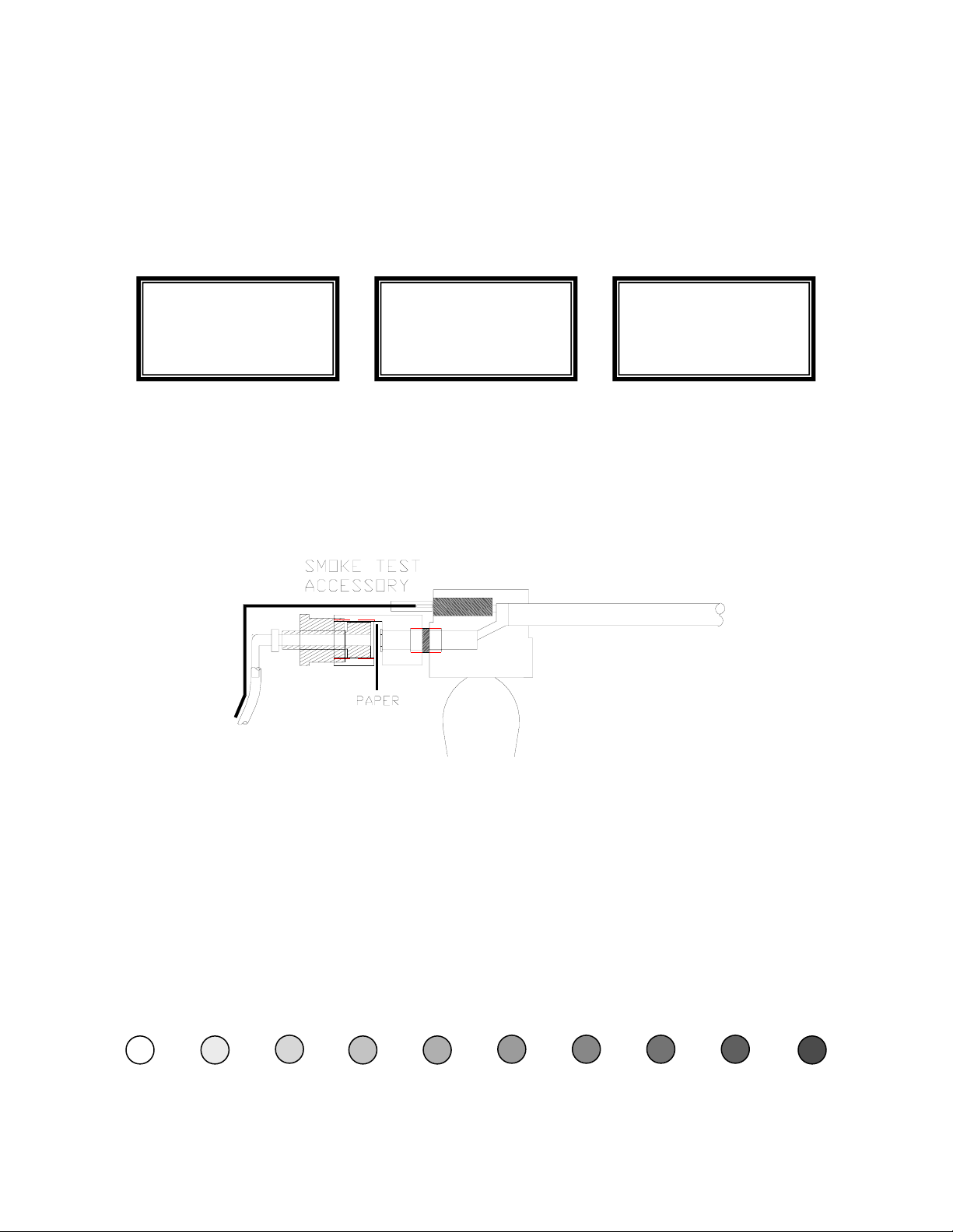
THE SMOKE TEST
(ASTM METHOD D2156)
The smoke test accessory, shown below, is required to perform smoke tests. If you
wish to take a measurement of the smoke using the smoke spot method, press and
hold the PUMP button for 3 seconds. The pump will stop and the first screen
shown below will appear on the display.
The instrument is waiting for you to take out a piece of the smoke paper and insert
it in the cut out provided in the probe handle. To do this you must first loosen the
thumbscrew to make room for the paper and then screw it back tightly so that there
is no leak. When you are ready, push the ENTER key.
The smoke test will begin and the display will read “Running 1:26” and will count
down. The pump will be on and drawing a sample at 750 cc/min. At the end of the
test the pump will stop again and the message “Completed!” will appear. Remove
the smoke paper as instructed. Tighten the thumbscrew to avoid any leaks and push
any button to continue with your measurements. Take out the smoke chart that
comes with the instrument and compare the paper's discoloration with the standard
shades of grey on the chart. The number corresponding to the closest match is the
smoke number.
0 1 2 3 4 5 6 7 8 9
SMOKE TEST
Enter to Begin
Shift to Abort
SMOKE TEST
Running 1:26
Shift to Abort
SMOKE TEST
Completed!
Remove Paper

15
CHAPTER 4
ANALYZER DESCRIPTION
A.POWER REQUIREMENTS
The Model 500 is designed to operate from 4 AA cells supplying a voltage of 4.0
to 6.5 Volts.
The flexible design allows for the use of either 4 AA alkaline primary (non
rechargeable) batteries, or 4 nickel-metal-hydride rechargeable cells. Rechargeable
batteries are recommended and are supplied with the analyzer. If you want to use
non-rechargeable batteries, use the battery holder supplied. Be sure to turn off the
DC charge switch located inside the unit.
A wall-mounted 110/220 volt AC charger is supplied with the high performance
(2500 mAH cells) Ni-MH cells and can be used to charge the batteries or operate
the unit continuously from an AC power source.
NOTE: Non-rechargeable batteries may explode or leak if the AC adapter or
another battery charger is accidentally connected. If you are using alkaline
(non-rechargeable) batteries, be sure to disable the AC charger connection by
toggling the DC CHARGE SWITCH, located next to the batteries, to the down
position marked ‘Alkaline’. See figure 4, page 48.
Battery life is approximately 6-8 hours of continuous operation. If you are using
the thermoelectric cooler, battery life is two hours.
You can check the condition of the batteries at any time by pressing the STATUS
button twice to display the second status screen. The following screen will appear
on the display:
STATUS SCREEN 2
Version: 5.0+
Serial #: 12345
Battery: 5.65 V
Fuel: #2 OIL
16
When the battery voltage indicated drops to 4.6 Volts for alkaline or 4.2 Volts for
rechargeables, you have only a few more minutes of battery life remaining. Using
the printer will further reduce battery power. Always check the battery voltage
with the pump turned on.
If you are using non rechargeable batteries the voltage will drop slowly and
gradually from 6 Volts to 4 Volts. If you are using rechargeable batteries the
voltage will stay fixed for several hours at 4.8 Volts before starting to drop rapidly.
In addition to the battery condition indication, there will be a warning during
instrument operation and also at start up, if the batteries are low.
If you are using the thermoelectric cooler assembly, reduce the cooler duty cycle to
extend the battery life. To further prolong battery life, you can turn off the
display’s back light illumination.
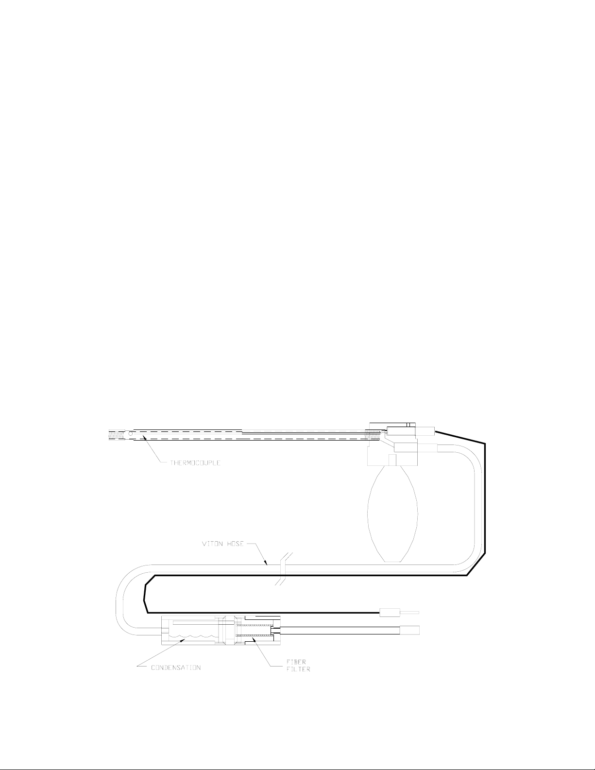
B. SAMPLE FLOW DESCRIPTION
During operation, the metal tube of the probe (see figure 1) is inserted into the
stack. A small pump located inside the unit draws a sample of the stack gases into
the instrument for analysis. The probe assembly and sensor housing are described
below.
FIGURE 1

17
The probe assembly consists of the following components:
•A 9" long 3/8" OD piece of inconel tubing and an inconel-sheathed type K
thermocouple located inside the inconel tube for protection. Both probe and
thermocouple are mounted on an aluminum head that includes a support handle.
•A 10 ft. long 1/4/” OD Viton sampling hose and thermocouple extension cable
equipped with quick disconnects on both sides for easy storage. Viton tubing is
used to prevent adsorption of NO2and SO2gases from the sample.
•A condensation trap and particulate filter assembly to remove the excess water
and clean the sample. The condensation trap is mounted for convenience to the
side of the hand-held analyzer. Figure 1 shows the probe assembly. The
optional thermoelectric cooler assembly replaces the condensation trap.
C.THERMOELECTRICALLY COOLED CONDENSATION TRAP
The thermoelectrically cooled condensation trap, better known as “Peltier Drier” is
an optional accessory device for the model 500 emissions analyzer.
Its purpose is to replace the standard condensation trap of the Model 500 for those
critical applications, that demand higher accuracy for the measurement of nitrogen
dioxide (NO2) and sulfur dioxide (SO2).
NO2and SO2are gases that are highly soluble in water. The exhaust sample
contains typically between 5% and 20% of water vapor, most of which will
condense in the probe and sample line.
To prevent significant loss of NO2and SO2during transport of the sample from the
probe to the analyzer, the following conditions must be satisfied:
1. Rapid sample transport. This is accomplished by maintaining a high flow
rate using a relatively small diameter sampling line.
2. Use of a sample line made from a highly hydrophobic material. A Teflon
sample line limited to 15 ft. long is used.
3. Minimum contact of the gas sample with the water collection mechanism
and also no additional condensation occurring following the Peltier drier.

18
This is accomplished by using a specially designed Peltier cooled manifold
to separate the gas from the water.
The following outline drawing illustrates the drier’s operation.
Mount the Peltier drier to the side of the ENERAC using the two thumbscrews.
Make a tight connection so that the heatsink makes good contact with the
ENERAC case.
The sample consisting of gas and partially condensed water vapor enters the drier
through the “SAMPLE INLET”. It flows through multiple narrow
thermoelectrically cooled passages, where total separation of gas and vapor occurs.
The dried sample makes a 180 degree turn, flowing upwards and goes through an
optional membrane filter exiting through the “SAMPLE OUTLET”. To maintain
proper operation the analyzer should be mounted either in a horizontal or vertical
position.
Check the disposable filter inside the Peltier drier filter holder. Make sure that the
filter is clean and dry. Secure the cover and check that the condensation trap is
also screwed tightly to prevent air leaks.
The condensation trap will probably fill with water after 2 to 4 hours depending on
the fuel used. To empty the condensation trap simply disconnect it from the
manifold by unscrewing it. When replacing it, be careful to seat the O-ring
properly.
FIGURE 2

19
The Peltier drier requires electrical power for operation. This is available from the
analyzer through the drier’s electrical connector. When operating the Peltier drier,
the analyzer’s battery life is limited to 2 hours, approximately. It is therefore
recommended, but not necessary, to use the battery charger for longer operation.
The Peltier drier will maintain the sample at a certain temperature below ambient
temperature to ensure no further condensation inside the analyzer. You can control
this temperature differential by adjusting the “COOLER DUTY CYCLE”, if
necessary.
The following table shows the approximate relation between duty cycle and
temperature differential:
DUTY CYCLE SAMPLE TEMP AMBIENT TEMP (°F)*
50% -9
75% -13
100% -16
*At 75°F ambient.
Battery life for the analyzer with the Drier in operation is approximately 2.5 hours
for 50% duty cycle to 1.5 hours for 100% duty cycle, assuming freshly charged
batteries, or new alkaline batteries.
This temperature differential between sample temperature and ambient temperature
is set at the factory to 70% but can be adjusted as follows:
1. Press the SHIFT key. SETUP MENU will be displayed.
2. Press the ENTER key to select SYSTEM SETUP.
3. Press the UP/DOWN keys until the cursor points to COOLER DUTY.
4. Press the ENTER key.
5. Use the UP/DOWN keys to set the Peltier duty cycle. A minimum of 50% is
recommended.
6. Press the ENTER key.
Table of contents
Other ENERAC Measuring Instrument manuals


Popular Measuring Instrument manuals by other brands


Aerospace Logic
Aerospace Logic OPT200XX Series Operation guide

Flin Energy
Flin Energy GPRS user manual

GOMETRICS
GOMETRICS T214 user manual

Newport Electronics
Newport Electronics INFINITY Series Operator's manual

Nomestic
Nomestic Airsight user manual

Geotech
Geotech 1.66 Reclaimer Installation and operation manual