Ijinus LNU User manual

Installation Guide
LNU : Battery powered ultrasonic level sensors
Measurement of water heights
K0J00016-EN-A02 (2019-07-12)

LNU sensor : Installation & programming
Installation Guide K0J00016-EN-A02
IJINUS – 25 ZA de Kervidanou 3 – 29300 MELLAC – FRANCE -www.ijinus.com - sales@ijinus.com
2
Table of contents
Table of contents ...............................................................................................................................................................2
1. Introduction....................................................................................................................................................................3
2. Three main ranges of measurements (depending on max distance to measure) .......................................................3
3. Equipment (4 configuration examples) .........................................................................................................................4
b. Permanent installation of a unique level sensor (continuous monitoring or self-monitoring of water networks)...5
c. Permanent installation of a several level sensors and a logger (continuous monitoring or self-monitoring of water
networks):...........................................................................................................................................................................5
d. Other configurations...................................................................................................................................................5
4. Quick configuration with the software Avelour ...........................................................................................................6
a. Necessary equipment .................................................................................................................................................6
a. Prerequisite.................................................................................................................................................................6
b. First step : Run Avelour and connect to the sensor to configure ...............................................................................7
c. Second step : Selection of the sensor to configure, eventually a firmware update would be suggested .................7
d. Third step : Configuration of Measures part ..............................................................................................................8
Calibration of the sensor Case N°1 (Ideal)........................................................................................................................11
Calibration of the sensor Case N°2 (Classic example of a manhole with an invert).........................................................12
Calibration of the sensor Case N°3 (complex) – Expert mode..........................................................................................14
e. Fourth step : Data reading in real time.....................................................................................................................18
f. Fifth Step : Retrieve and see locally your data by radio ...........................................................................................18
g. Sixth step: Data export .............................................................................................................................................19
h. Seventh step : Pair devices .......................................................................................................................................19
i. Eighth step : Data sending ........................................................................................................................................20
5. Elements for good practice and installation examples...............................................................................................24
6. Procedure for inserting the SIM card ..........................................................................................................................27
7. Procedure for inserting the SIM card ..........................................................................................................................28
8. Instructions concerning ATEX devices .........................................................................................................................29
9. Document History ........................................................................................................................................................30
LNU sensor : Installation & programming
Installation Guide K0J00016-EN-A02
IJINUS – 25 ZA de Kervidanou 3 – 29300 MELLAC – FRANCE -www.ijinus.com - sales@ijinus.com
3
1. Introduction
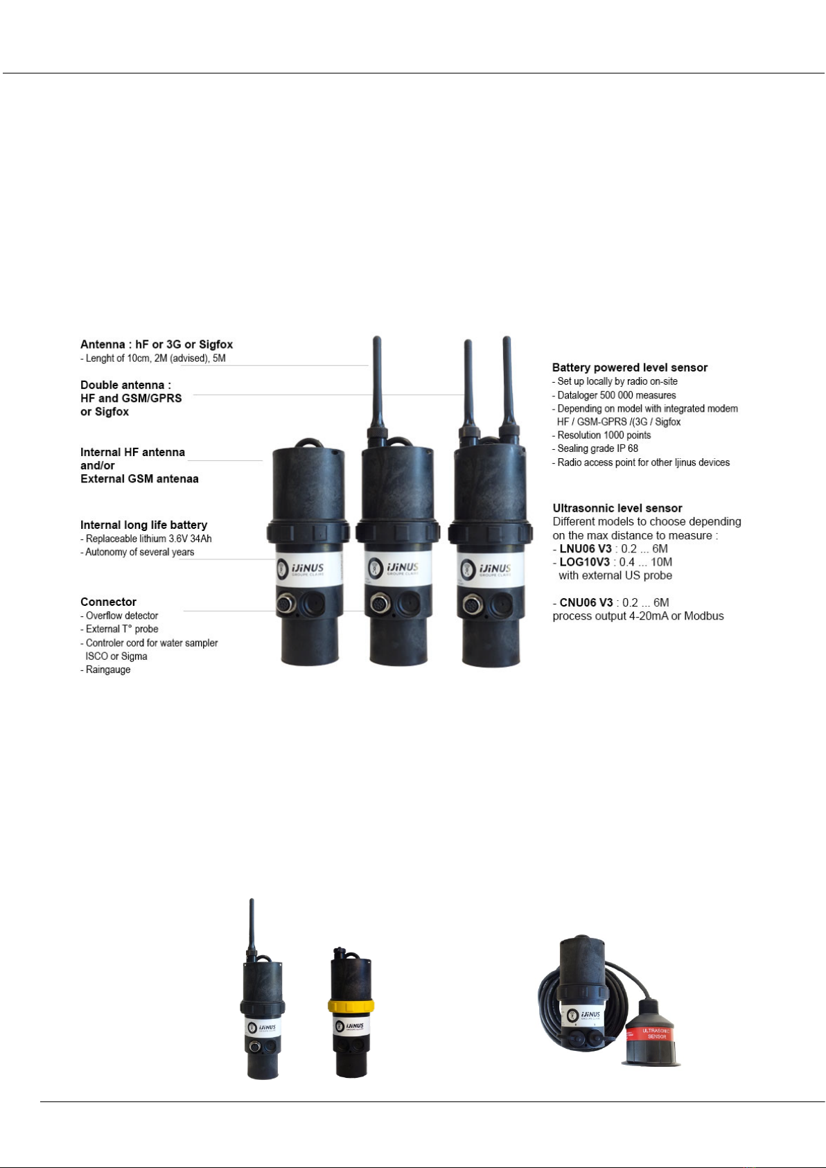
This solution is an Ijinus product grouping water height measurement by aerial ultrasonic,
with automatic measurement cycle changes depending on thresholds, flow rate
transformation through conversion tables. Some sensors are equipped with connectors
for coupling with an overflow detector or to control water sampler.
In addition to measuring, these sensors can also be paired with others or serve as data
concentrators (for version with communication 3g or Sigfox).
2. Three main ranges of measurements (depending on max distance to measure)
LNU06V3 & LNU06V3-EX
Measure up to 6m
LOG10V3
Measure up to 10m
External ultrasonic
probe
LNU sensor : Installation & programming
Installation Guide K0J00016-EN-A02
IJINUS – 25 ZA de Kervidanou 3 – 29300 MELLAC – FRANCE -www.ijinus.com - sales@ijinus.com
4
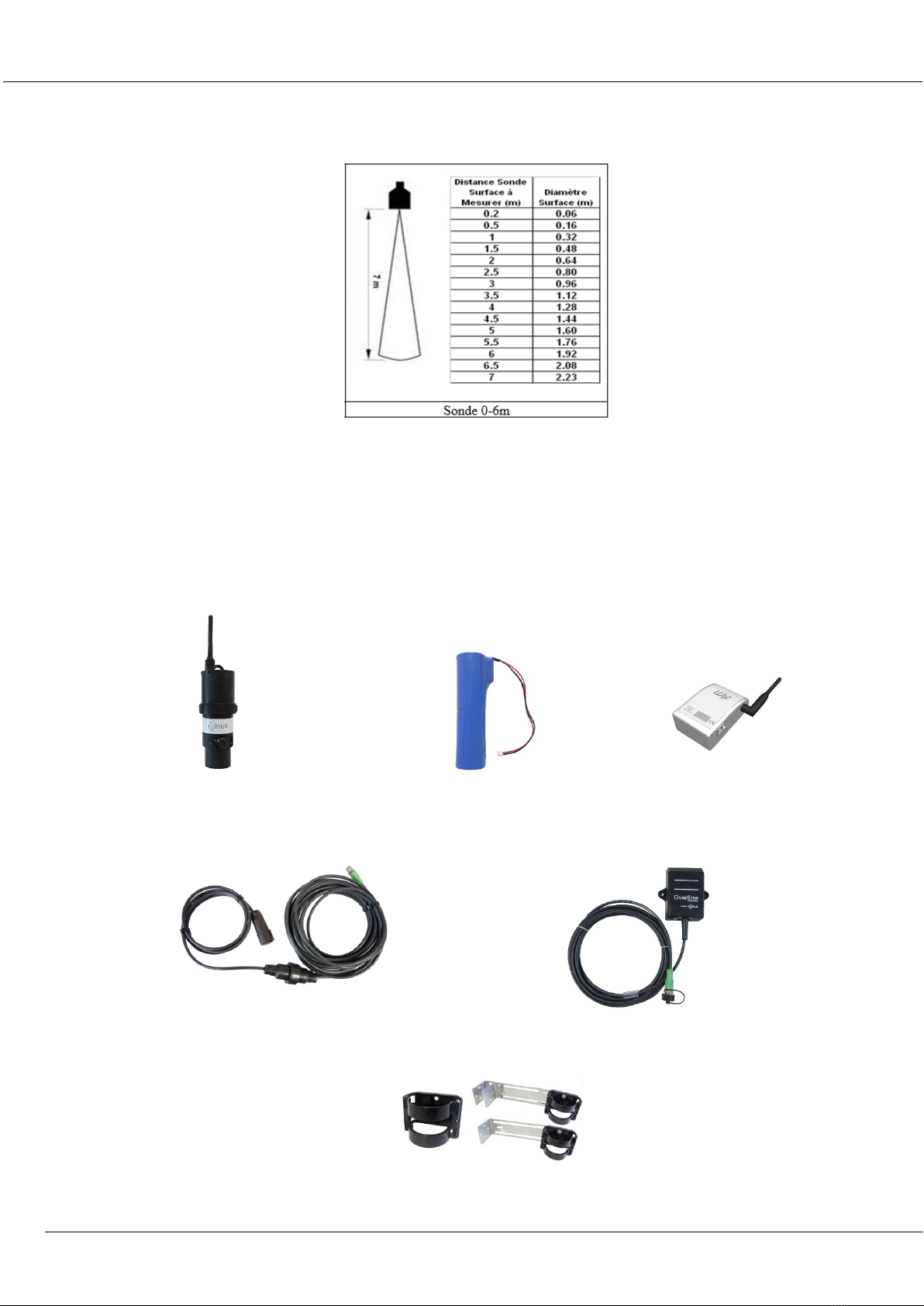
For example the figure below shows the indication of the diameter of the area that will be studied by two
probes models (6 and 10m) according to the distance :
3. Equipment (4 configuration examples)
a. Temporary Installation
The sensor is autonomous and battery powered (lithium battery), it measures water level by air ultrasonic
waves. It has internal logger and data can be retrieved on-site (by radio using the programming kit : Wiji).
Fixations: Bracket, fixations either with single
or double metal plate with bracket
Ultrasonic sensor
Lithium battery
Programming kit
Water sampler cable
Overflow detector

LNU sensor : Installation & programming
Installation Guide K0J00016-EN-A02
IJINUS – 25 ZA de Kervidanou 3 – 29300 MELLAC – FRANCE -www.ijinus.com - sales@ijinus.com
5
b. Permanent installation of a unique level sensor (continuous monitoring or self-monitoring of
water networks)
For level measurement that is battery powered (replaceable lithium) and send data by GSM/GPRS, 3G (depending on
the sensor).
Sensor integrating a logger, communication GSM/GPRS, 3G modem and its deported antenna
c. Permanent installation of a several level sensors and a logger (continuous monitoring or self-
monitoring of water networks):
For level measurement that is battery powered (replaceable lithium) send data locally by short range radio, and
the logger (LOG V3) retrieve the data of the level sensors or others and send them by GSM/GPRS.
Data logger as a radio/3G access point
d. Other configurations.
Actually, the communication protocols available for the Ijinus devices are the following:

LNU sensor : Installation & programming
Installation Guide K0J00016-EN-A02
IJINUS – 25 ZA de Kervidanou 3 – 29300 MELLAC – FRANCE -www.ijinus.com - sales@ijinus.com
6
-Radio for a HF configuration and data retrieval: Wiji protocol
-Wireless communication for remote data monitoring: 2G (for Sms), GPRS, 3G, Sigfox, NB-IoT (LTE-M 3GPP)
-Wired communication with a PLC: Modbus RS 485
-Currently being integrated: 4G, 6LOWPAN
4. Quick configuration with the software Avelour
We will show here the classical version of the system programing, level measurement and data sending by
Gsm/Gprs/3G.
a. Necessary equipment
- The software Avelour in 6.6 version minimum
- Programing Wiji kit or Wiji key
Avelour
Wiji kit
Wiji key
a. Prerequisite
- The material is considered to be directly functional, the battery can be use directly
LNU sensor : Installation & programming
Installation Guide K0J00016-EN-A02
IJINUS – 25 ZA de Kervidanou 3 – 29300 MELLAC – FRANCE -www.ijinus.com - sales@ijinus.com
7
- All indications contained in this document correspond to programming with Avelour in version 6.04
mini
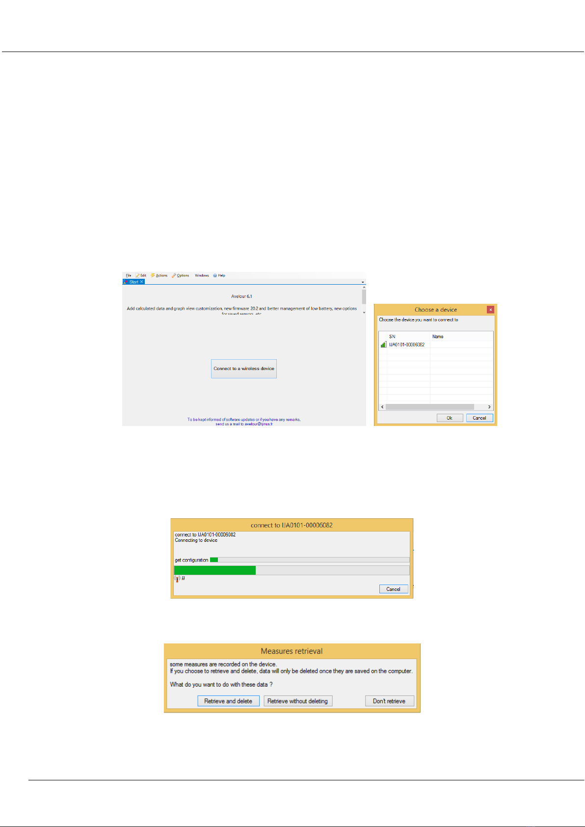
b. First step : Run Avelour and connect to the sensor to configure
After connection of the Wiji kit equipped with its antenna (or the Wiji key) on your laptop or PC USB port, run
the software Avelour version 6.04 minimum. Click on the button “Connect to a wireless device” then the sensor
or logger will be directly visible by its part number (SN) without the need to activate anything else (ex:IJA0101-
0000 3559). Locate the sensor's serial number (SN) on the sensor label and click "OK".
On the first connection with the sensor only the serial number will appear. The following connections you will
see also the name of the installation site or another name that you define.
c. Second step : Selection of the sensor to configure, eventually a firmware update would
be suggested
During its connection with the sensor, the following pop up appears:
When connected, and only if the sensor already has measures in memory, the following options will suggest you
to retrieve the measures:
After your choice of these options, if the sensor is not up to date (case of new firmware developed since your
last connection or you are now connected with a new version of the software Avelour). It is strongly
recommended to read carefully the different messages in the options windows.
LNU sensor : Installation & programming
Installation Guide K0J00016-EN-A02
IJINUS – 25 ZA de Kervidanou 3 – 29300 MELLAC – FRANCE -www.ijinus.com - sales@ijinus.com
8
The firmware update can last a moment so it is advised to do it while in your office. On-site prefer the best radio
connection (so not if the metal cover of a man hole is closed).
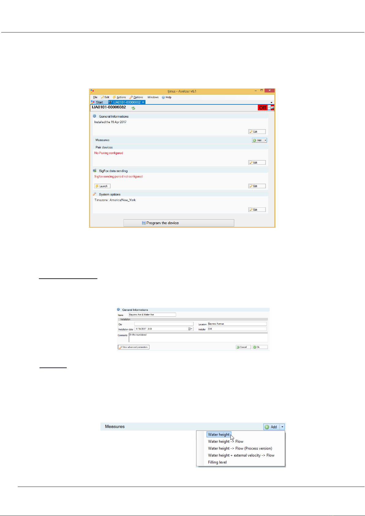
When the sensors is ready, Avelour will look like bellow :
d. Third step : Configuration of Measures part
This part is divided in several paragraphs. Each part will be detailed.
General informations
This part is useful to describe the measurement point. The most important information would be the name that
will help you to find your sensor at a future connection.
Measures
Choice of the application to configure
This part is the most important, it allows you to configure your sensor.
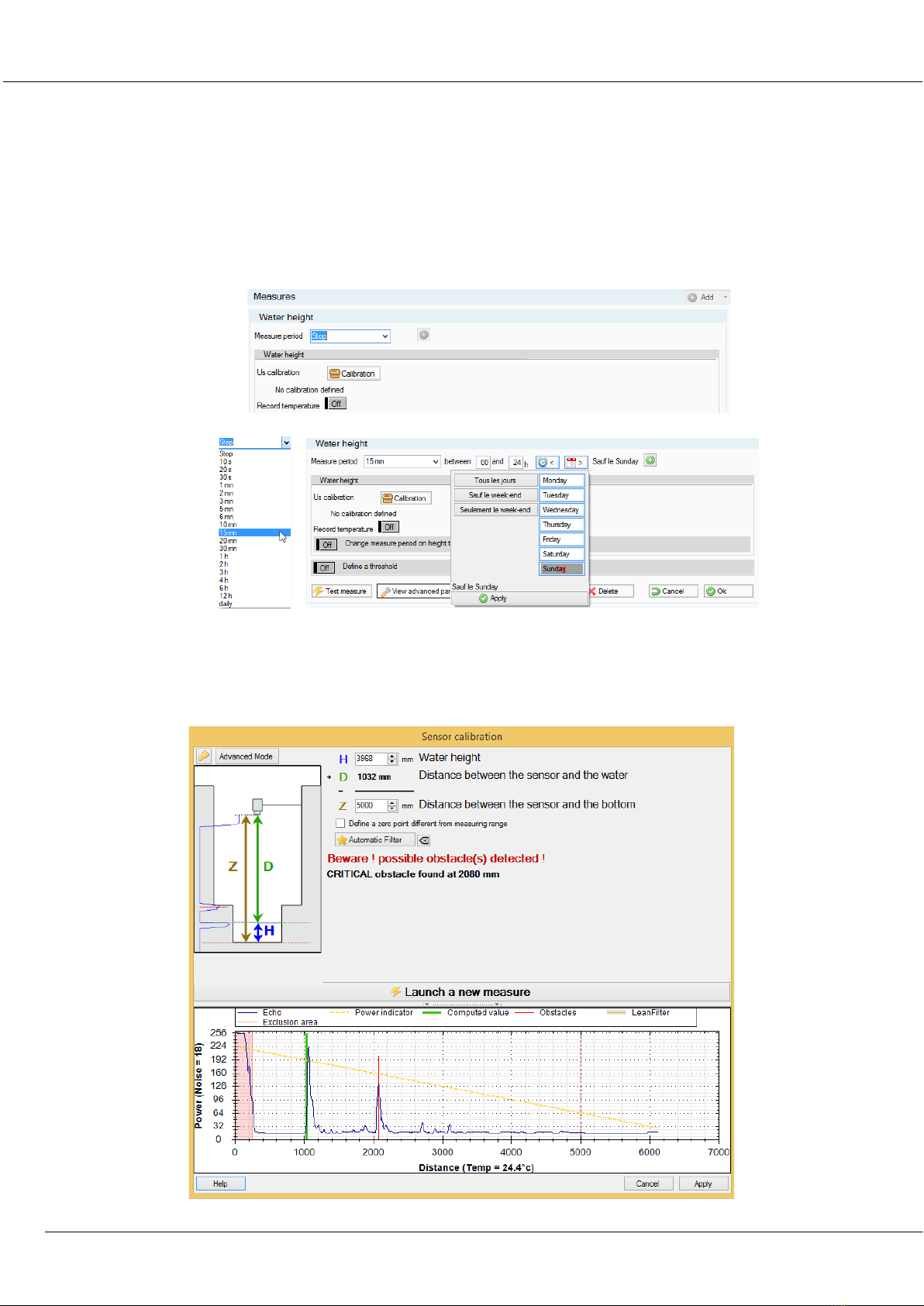
First of all, and the simplest click on the button “Add”, then choose “Water height”.
LNU sensor : Installation & programming
Installation Guide K0J00016-EN-A02
IJINUS – 25 ZA de Kervidanou 3 – 29300 MELLAC – FRANCE -www.ijinus.com - sales@ijinus.com
9
Choice of the measure period
In this new menu, select the period you want the sensor to measure (in this example every 15min)
To the right of the measure period selector, 2 little icons allowing a deferred programming according to the
time period and day of the week you can choose from. So far the sensor is not calibrated.
Calibration of the water height
After clicking the calibration button the bellow windows appears:
LNU sensor : Installation & programming
Installation Guide K0J00016-EN-A02
IJINUS – 25 ZA de Kervidanou 3 – 29300 MELLAC – FRANCE -www.ijinus.com - sales@ijinus.com
10
It is difficult to establish rules but globally 3 cases may arise:
CASE 1 : Ideal case: unique echo (test in lab or if the sensor front flat water surface for example)
A simple calibration would be possible.
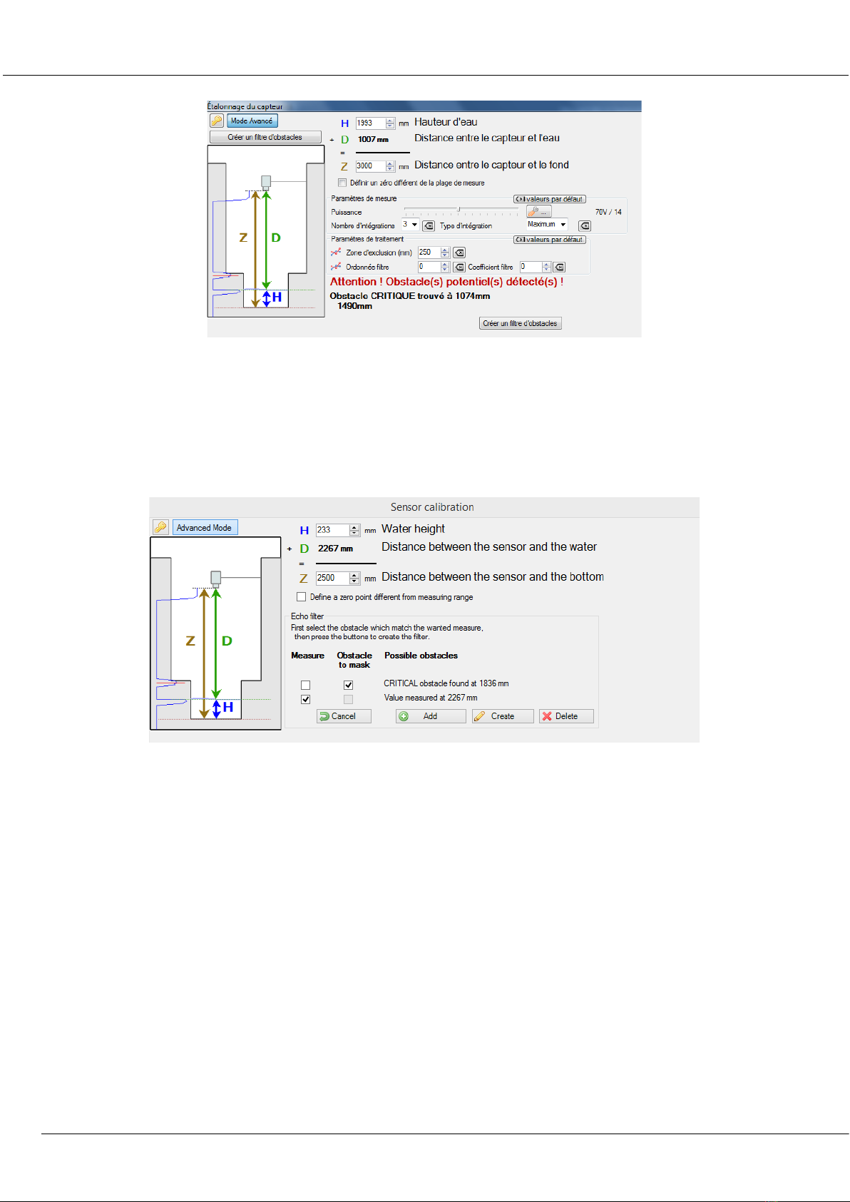
CASE 2 : Case of a classic man hole with at the bottom an invert. The figure bellow shows two echoes (the
invert and the water). A calibration in advanced mode will be possible. First check that the sensor is well
positioned, fronting and perpendicularto the water.
LNU sensor : Installation & programming
Installation Guide K0J00016-EN-A02
IJINUS – 25 ZA de Kervidanou 3 – 29300 MELLAC – FRANCE -www.ijinus.com - sales@ijinus.com
11
CASE 3 : Complex case
the presence of many echoes make difficult the calibration the easiest way. A priority should be to move the
sensor if possible otherwise go to the expert mode. (Only for experienced users).
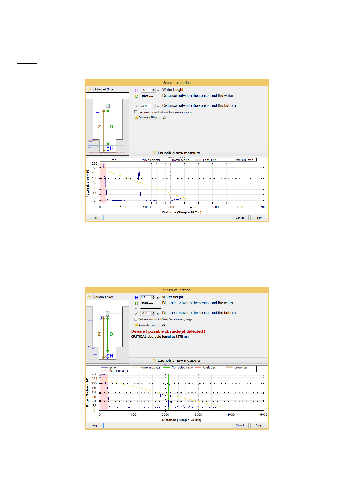
Calibration of the sensor Case N°1 (Ideal)
The first case presenting only one echo, you only need to adjust the water height Hor the maximal distance
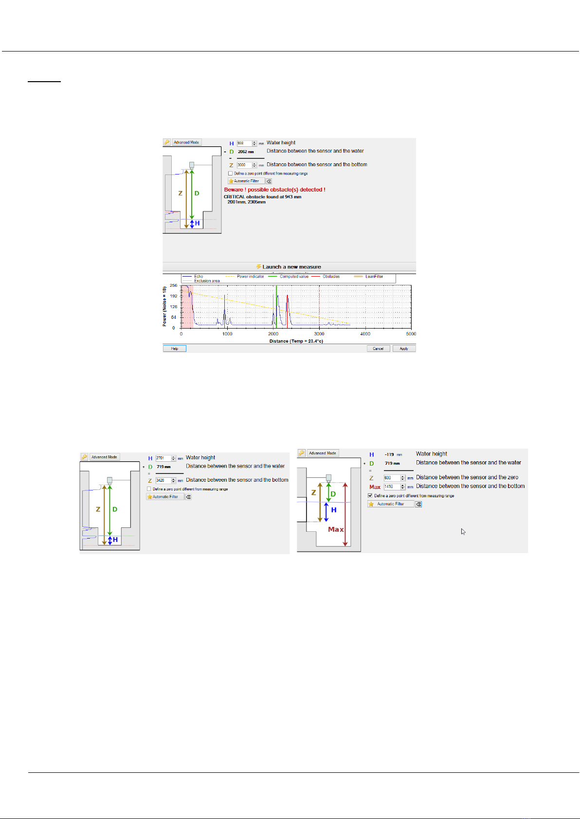
between the sensor and the bottom Zand relaunch a measure. Note that it is possible to define a different zero
point (zero at the level of an overflow threshold for example), very useful for stormwater overflows.
Zero of the sensor (example of ideal case) – On the right a different zero point
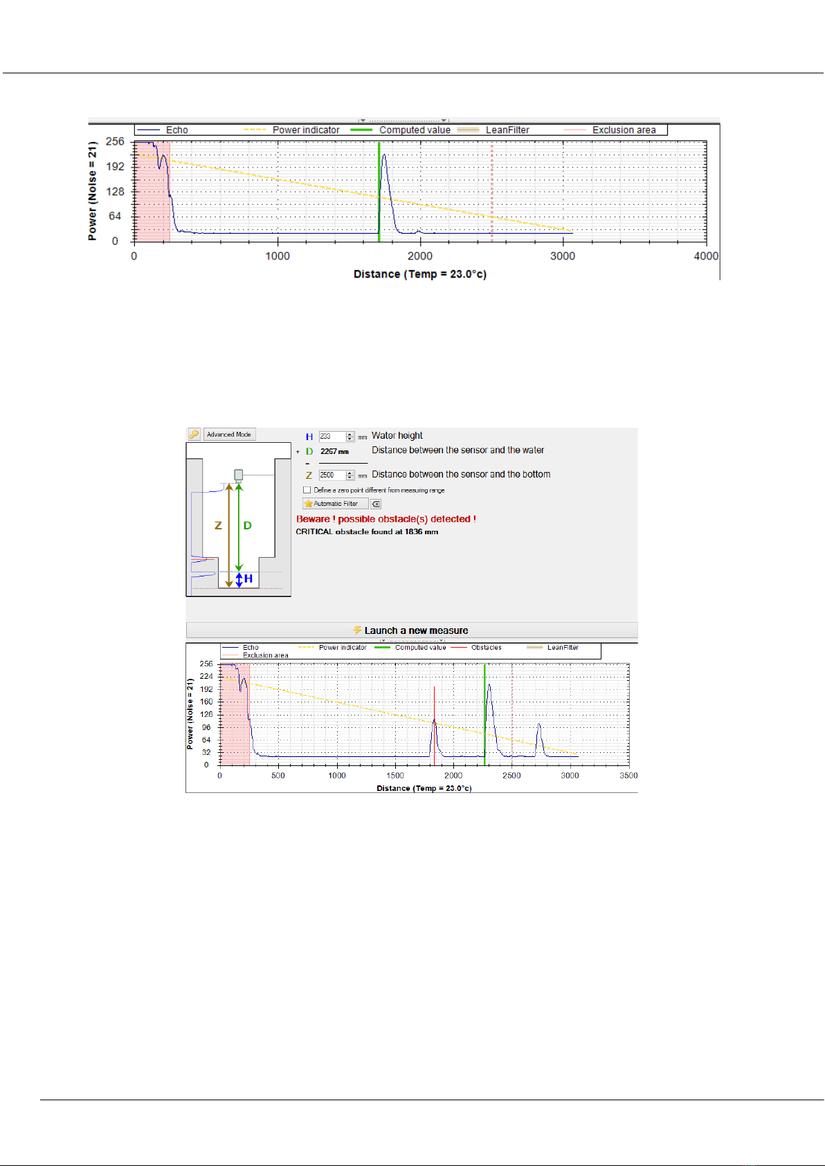
Once done, the calibration has to be validated by clicking on “Apply” button. Configuration of this are then
automatically saved in a file called “configuration” that is visible with the software even when not connected to
the sensor. Please note that the figure presenting the echo as an indicator so called of power, showing by a
yellow dot line (oblique from left to right). This one is very useful to fine tune the sensor. The echo should
ideally be upward that line. A weak echo means measurement not precise, a too high echo provides accurate
measures but use faster the energy. A temperature checking during the measure has also to be done (here 25 at
the bottom of the graph). While the measure is temperature compensated, you should calibrate a sensor when
temperature are too high and then asking it to measure on a different environment (typical case of 15°C under a
LNU sensor : Installation & programming
Installation Guide K0J00016-EN-A02
IJINUS – 25 ZA de Kervidanou 3 – 29300 MELLAC – FRANCE -www.ijinus.com - sales@ijinus.com
12
sewer manhole).
Calibration of the sensor Case N°2 (Classic example of a manhole with an invert)
In case no. 2, with an echo having several peaks, the software indicates the presence of "critical" obstacles that can
disturb the measurement if one remains in simple calibration. These critical obstacles appear in red on the graph, while
the echo reported by the sensor as the measurement is shown in green. The power indicator is always present.
In this case, follow the following procedure:
- Activate the advance mode by clicking on the button at the top,
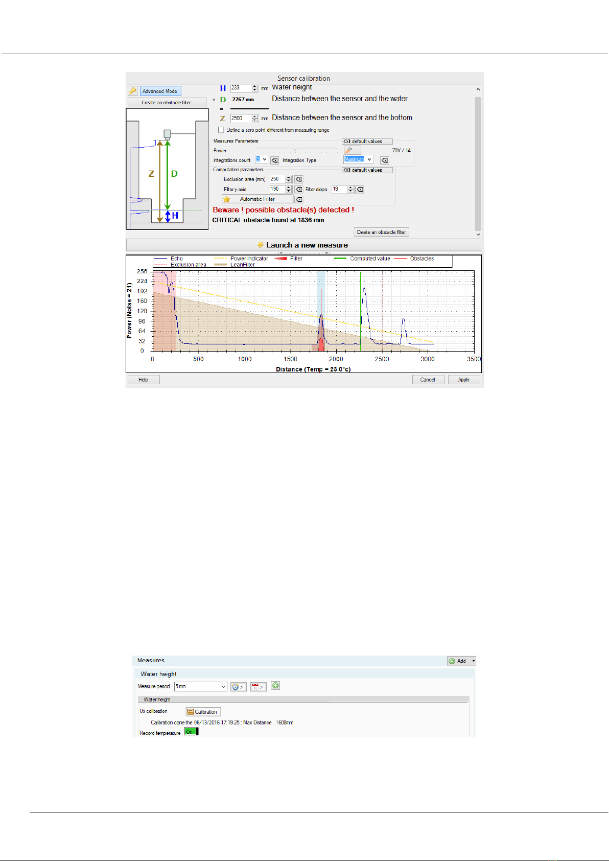
The software displays a first stage of calibration that is more precise named “Measures parameters” : This parameter
allows to extend the exclusion area corresponding roughly to the dead band of the sensor. This parameter is to be
modified, mainly in the case of probes 0-6m if there are interfering echoes in this zone, or in the case of a probe
mounted on an angular return bracket. The manipulation consists in increasing the value of the pink zone so it covers
the different peaks for distances close to the probe,
LNU sensor : Installation & programming
Installation Guide K0J00016-EN-A02
IJINUS – 25 ZA de Kervidanou 3 – 29300 MELLAC – FRANCE -www.ijinus.com - sales@ijinus.com
13
- This advanced mode also allows to create “obstacle filter” that consist in masking obstacles echoes that disrupt the
measure like in the case of invert, ladder rungs present in the field of view of the sensor.
After clicking on “Create an obstacle filter”, you need to choose with the tick box the obstacle matching the wanted
measure (water height), press “Create”.
- Once the filter has been made and checked, you need to validate it by clicking the button “Launch a new measure”,
then adjust either the H or the H2 to ensure the quality of water height measurements.
Finally this advanced mode allows to two other optimization operations and another filtered pparticularly efficient.
One computation parameter often named “oblique filter” works as follow :
- Choose a Filter y-axis of 160
- Adjust the filter slope until it becomes parallel to the power indicator (yellow line) and ends to the zero of the sensor.
- If you can’t see that oblique filter, adjust the y-axis.
The integrations count option, available for minimum, average and maximum, is the successive ultrasonic shoots
treatment (3 by default). The average option does an average of those shoots. Most of the time the maximum option is
to be chosen to get reliable measurements (and especially in presence of condensation) but also depends of the power
setting of the sensor.
LNU sensor : Installation & programming
Installation Guide K0J00016-EN-A02
IJINUS – 25 ZA de Kervidanou 3 – 29300 MELLAC – FRANCE -www.ijinus.com - sales@ijinus.com
14
Finally, you need to launch a new measure to check the relevance of the result so :
- The green line position used for the measure,
- Values of the echo slightly higher than the power indicator,
- and validate by pressing the Apply button
Calibration of the sensor Case N°3 (complex) – Expert mode
The expert mode is to be used only in complex cases and need user experience and knowledge of
ultrasonic measure data processing. Various parameters and options are then available but won’t be in
this document. You need a password to go on expert mode. Please contact your sales representative or
the after sale services, the password as well as some information will be given.
Temperature recording
You can log the temperature thank to the internal T probe used to compensate the level measurement with ultrasonic.
For information, the sound speed in the air at 10°C is 337,6m/s.

LNU sensor : Installation & programming
Installation Guide K0J00016-EN-A02
IJINUS – 25 ZA de Kervidanou 3 – 29300 MELLAC – FRANCE -www.ijinus.com - sales@ijinus.com
15
Change measure period on height threshold
For some sensors, you can have two different time of data acquisition depending on water height measures. For
example, you can measure every hour when le level is low and accelerate to 2 minutes when level goes above a
threshold. This measurement period acceleration can be set to some time slots, following a exceedance of level (with or
without hysteresis) and with the choice of a minimum time before deceleration.
The limit of this acceleration is it can only be done with a water height measurement. If you wish to accelerate the
measures as soon as the water go over one level between two measurements, you have to connect one of our overflow
detectors to the ultrasonic level sensor.
Define a threshold / software overflow detection (Two can be set)
After the programing of the first threshold, you can then define a second one.
To go further and use the advanced parameters: Zoom on the debugging echoes (acoustic signature) and the
replacement values in case of loss of echoes.
All advanced parameters won’t be explain here, but two zooms on very useful functionalities:
Debugging echoes
The record of debugging echoes is very useful to log when there is a difference between two successive measures (on
rise and or on lowering : here 75 for both), the acoustic signature of the measures, or the famous ultrasonic echo. A post
review allows you to evaluate the quality of level measurements and to correct them if needed.
For your first or complex installations, we strongly advice to activate this functionality.
Height value for loss of echo
In the field of ultrasonic, a loss of echoes is reflected by the absence of peaks (or a very weak peaks not detected as an
obstacle) on echoes that materialize by a maximal height, the Z you define during the calibration. This function is used

LNU sensor : Installation & programming
Installation Guide K0J00016-EN-A02
IJINUS – 25 ZA de Kervidanou 3 – 29300 MELLAC – FRANCE -www.ijinus.com - sales@ijinus.com
16
when the sensor encounters this situation, to replace this value “a priori” false by another one define by the user :
The last valid value, a value you define, no value, …
This option has to be appropriately used, it never should compensate a not completed or not adapted calibration.
Programing for flow rate calculation from height measures and control a water sampler
Before completing this chapter, it is important to keep in mind that a flow rate measure is obtained by two factors 1)
the wet area and 2) the average velocity. The sensors described in this document only measure water height (that
allows wet area calculation via the collector shape) but never a velocity measure.
Nerveless some tools to transform water height measured in flow rate (then in volume) by conversion table or
measuring system on threshold are available. It is the user’s responsibility to choose the transforming tool. In this case,
it has to be chosen at the beginning of the programing (or to modified) height/flow rate like shown below.
Once the programing choice has been done, an example sheet of conversion is available:
An Excel file will then open with in summary the different type of use. For example in case of circular collector, the sheet
called Height/surface - circle allows you to generate a value table (mm) / yet Surface (mm^2) for a circular collector
(here for 1500 mm) with the possibility to integrate mud height, this for a scale every 5 mm). Only the yellow cells have
to be filled, conversion is done automatically.

LNU sensor : Installation & programming
Installation Guide K0J00016-EN-A02
IJINUS – 25 ZA de Kervidanou 3 – 29300 MELLAC – FRANCE -www.ijinus.com - sales@ijinus.com
17
You need to select, copy the bloc Height/Surface in Excel (bellow example) then after activated the Height/flow table in
Avelour, paste the data from clipboard. Final validation is done by pressing the OK button
This operation validates the input of these data in the table by displaying the number of lines, then can activate,
depending on calculation needs, flow logs and eventually to control a water sampler.
Once the programming is done, a resume summarized your different choices
Finishing of the programming: you have to validate with the “Program the device” button to send the configuration in
the sensor memory:
After the saving operation is done please check that you have at the top right corner the two green sign showing that
the sensor working and recording, and also sending data. You can stop them both by pressing the red Stop icon, if
needed.
LNU sensor : Installation & programming
Installation Guide K0J00016-EN-A02
IJINUS – 25 ZA de Kervidanou 3 – 29300 MELLAC – FRANCE -www.ijinus.com - sales@ijinus.com
18
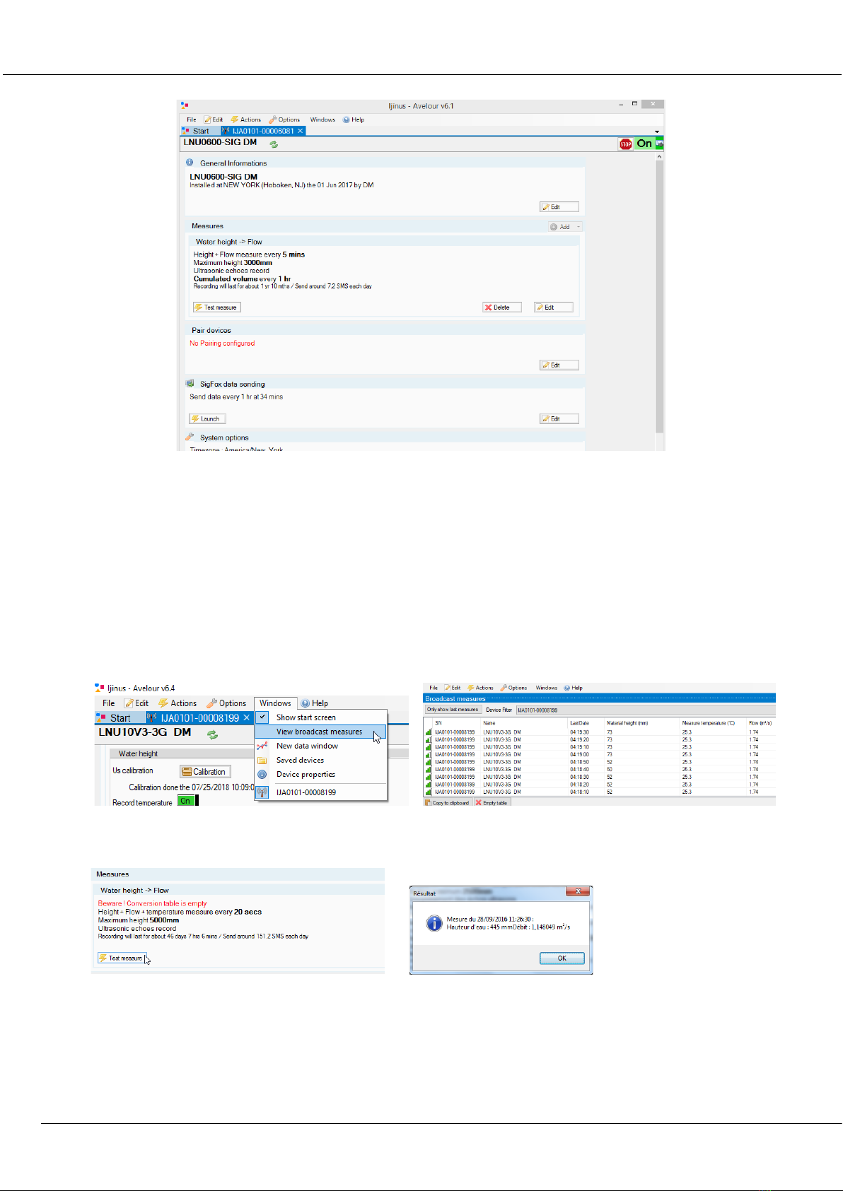
e. Fourth step : Data reading in real time
You Have two possibilities to read the data in real time : By pressing the “Test measure” button, or by selecting
on the main menu the window “View broadcast measures” (Main menu > Windows > View broadcast
measures)
View broadcast measures: this option opens a window showing the measures received by radio from Ijinus
sensors and loggers nearby.
Now you can also press the “Test measure” button for a direct reading
f. Fifth Step : Retrieve and see locally your data by radio
When connected to a sensor, the software directly asks you if you want to retrieve data. After you can find this
command from the main menu : Menu > Actions > Retrieve measures

LNU sensor : Installation & programming
Installation Guide K0J00016-EN-A02
IJINUS – 25 ZA de Kervidanou 3 – 29300 MELLAC – FRANCE -www.ijinus.com - sales@ijinus.com
19
You can view the data, even offline, on graphic and list. A graph configuration module allows you to changes colors,
thickness of lines, … , but also to apply statistical filters and formula to your data.
g. Sixth step: Data export
From The graph and/or list of data you find the tab “Export the measures” with the choice of different files format and
style of reports, from date to date, by month, or simply all data.
h. Seventh step : Pair devices
Our level sensor can retrieve locally the data from other sensors and logger nearby by radio, and send them with its
modem.
To do this you need to check in Avelour what devices can this sensors see around it. In the Pair devices part, click the
Edit button
Then you need to click the Refresh button to run the test. Simply tick the boxes corresponding to the devices you want
to associate.

LNU sensor : Installation & programming
Installation Guide K0J00016-EN-A02
IJINUS – 25 ZA de Kervidanou 3 – 29300 MELLAC – FRANCE -www.ijinus.com - sales@ijinus.com
20
Check the strength of the radio signal by placing the cursor on the bars indicator (Be careful the quality of radio signal is
nothing to compare with GSM/GPRS : -70 dB is a bad quality for radio and excellent for GSM/GPRS)
i. Eighth step : Data sending
As we said at the beginning of the document different ways to send data are possible like Sms and Gprs/3G/Ftp. In this
part I will show you the way to do it by Sigfox and GPRS. First keep in mind that on the installation location if you
already can’t find operator signal in surface, it will be even more difficult while under a metal cover in the manhole.
Sending by SIGFOX :
After clicking the Edit button, choose the sending period, define to send every day or only some of them. You can define
several periods. Depending on your configuration you may need to choose a minimum delay between 2 anticipated data
sending.
Finally you should run a test by clicking the Launch button to check if the data are sent to our website if your account is
created and the sensor already configured.
Other manuals for LNU
1
This manual suits for next models
1
Table of contents
Other Ijinus Accessories manuals


Popular Accessories manuals by other brands

Airmar
Airmar T42 Owner's guide and installation instructions

Logitech
Logitech Pen quick start guide

NEW BRUNSWICK SCIENTIFIC
NEW BRUNSWICK SCIENTIFIC Innova CO48 Assembly instructions

PCB Piezotronics
PCB Piezotronics 137B26 Installation and operating manual

LEGRAND
LEGRAND 6 946 90 quick start guide

CombiSteel
CombiSteel 7455.22 Series user manual


