Ikegami CCU-430 User manual

Products conforming to RoHS directive
UHK-430
CCU-430
4K/HD
Portable Camera System
OPERATION MANUAL
CCU
OFF
EXT
POWER
FILTER
HEAD
F2
F1
MIC
INCOM/ND
PGM/CC
MENU
VF
CHAR
CAM:400V T5A
POWER
CCU
CAM
TEMP FAN
ALARM
COMM
SDI
APC
GENLOCK
CCU STATUS
SHORT
OPEN
NORMAL
CABLE STATUS
OPT RX LEVEL
CAM
CCU
TALLY
ID
INTERCOM
PHONE
INIT/PM
CALL
COM
PRV
MIC
ON
OFF
PTT
MENU
USB
OPE
OFF


1710 Edition (E)
1
2
3
4
5
6
7
OUTLINE
NAME and FUNCTION
INSTALLATION and
CONNECTION
OPERATION
CAMERA SETTINGS and
ADJUSTMENT
CCU SETTINGS and
ADJUSTMENT
Helpful Technical
Information
8
TROUBLE SHOOTING
and MAINTENANCE
9
SPECIFICATIONS
CHANGING INFORMATION
UHK-430
CCU-430
4K/HD
Portable Camera System
OPERATION MANUAL

Copyright © 2016 Ikegami Tsushinki Co., Ltd.
We reserve the copyright on the software we create.
1RSDUWRIWKLVSXEOLFDWLRQPD\EHPRGL¿HGRUUHSURGXFHGLQDQ\IRUPRUE\DQ\PHDQVZLWKRXWSULRUZULWWHQSHUPLVVLRQIURP
Ikegami Tsushinki Co., Ltd.

PRODUCTS CONFORMING TO RoHS DIRECTIVE
i
UHK-430/CCU-430 1710 VER2 (E)
PRODUCTS CONFORMING TO RoHS DIRECTIVE
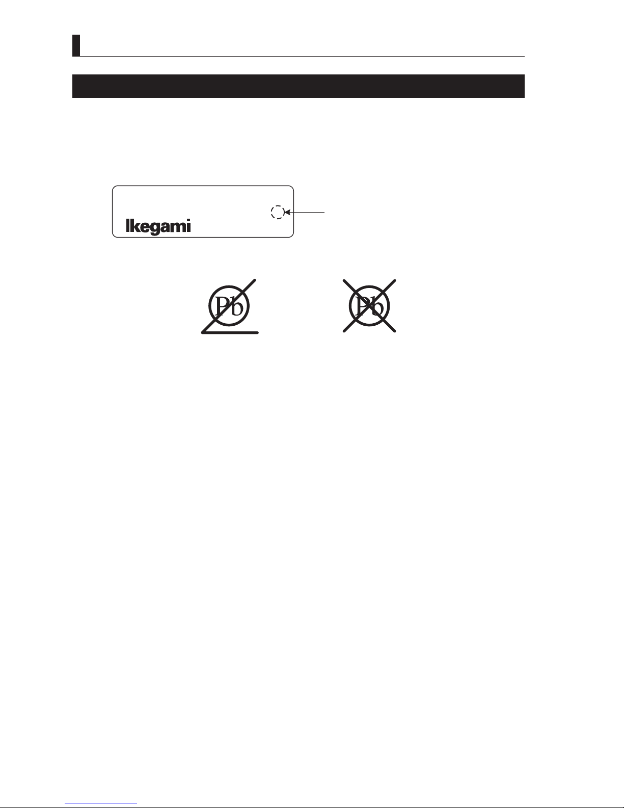
Following products described in this manual are products conforming to RoHS directive.
-UHK-430 ColorCamera
-CCU-430 CameraControlUnit
-SE-U430 SystemExpander
- VFE741D, VFL701D,VFL201D9LHZ¿QGHU
-OCP-300 Ethernet-CompatibleOperationControlPanel
-MCP-300 Ethernet-CompatibleMaintenanceControlPanel
-CPH-200 ControlPanelHub
-BSH-200 BaseStationHub
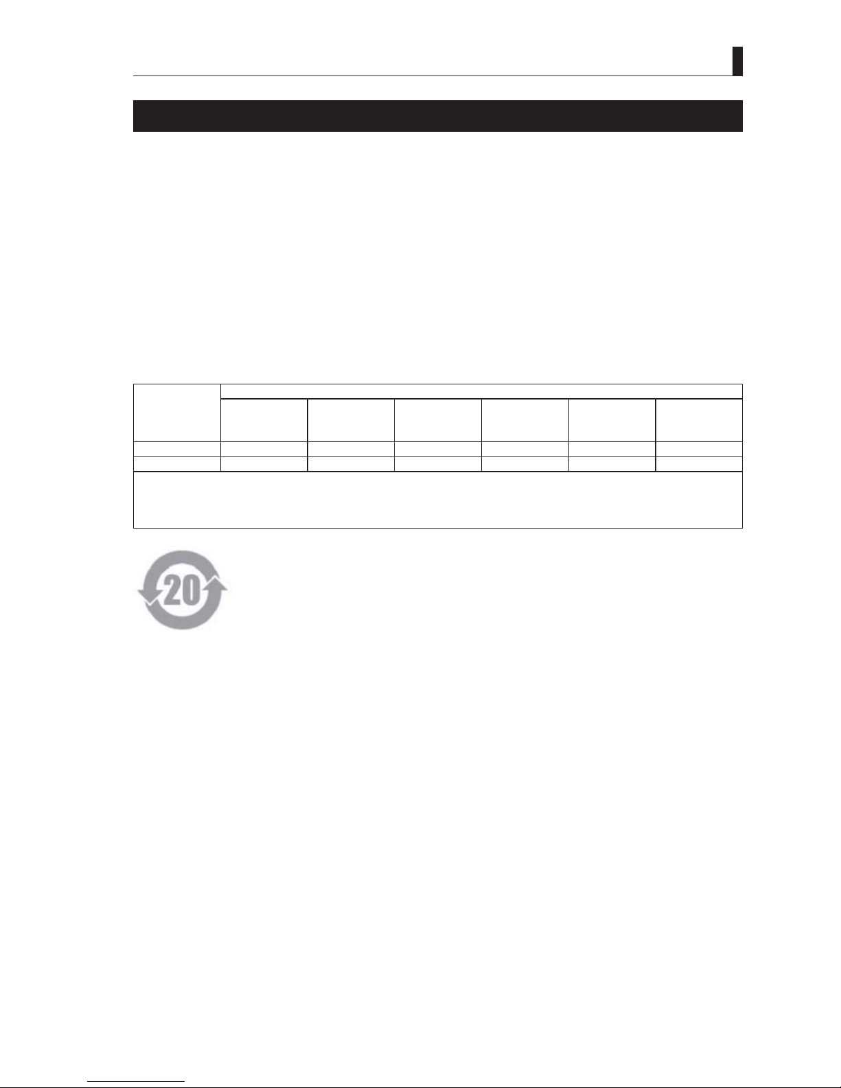
3URGXFWVFRQIRUPLQJWR5R+6GLUHFWLYHLQFOXGHSURGXFWVWKDWGRQRWFRQWDLQVSHFL¿HGKD]DUGRXVVXEVWDQFHVVXFKDVOHDGPHUFXU\
cadmium, hexavalent chromium, polybrominated biphenyl (PBB) and polybrominated diphenyl ether (PBDE) in electrical and
electronic equipment excluding following exemption applications based on the EU directive.
* About RoHS Directive
7KH5R+6GLUHFWLYHVWDQGVIRUWKH5HVWULFWLRQRIWKH8VHRI&HUWDLQ+D]DUGRXV6XEVWDQFHVLQ(OHFWULFDODQG(OHFWURQLF(TXLSPHQW
DQGLVRQHRIHQYLURQPHQWDOGLUHFWLYHVLQ(XURSH7KLVGLUHFWLYHUHVWULFWVWKHXVHRIVSHFL¿HGKD]DUGRXVVXEVWDQFHVLQHOHFWULFDODQG
electronic equipment.
●Applications exempted from RoHS directive compliance
Followings applications are permitted as exemptions from RoHS directive compliance.
0HUFXU\LQFRPSDFWÀXRUHVFHQWODPSVQRWH[FHHGLQJPJSHUODPS
0HUFXU\LQVWUDLJKWÀXRUHVFHQWODPSVIRUJHQHUDOSXUSRVHVQRWH[FHHGLQJ
-halophosphate10mg
WULSKRVSKDWHZLWKDQRUPDOOLIHWLPHPJ
- triphosphate with a long lifetime 8mg
0HUFXU\LQVWUDLJKWÀXRUHVFHQWODPSVIRUVSHFLDOSXUSRVHV
0HUFXU\LQRWKHUODPSVQRWVSHFL¿FDOO\PHQWLRQHGLQWKLV$QQH[
/HDGLQWKHJODVVRIFDWKRGHUD\WXEHVHOHFWURQLFFRPSRQHQWVDQGÀXRUHVFHQWWXEHV
/HDGDVDQDOOR\LQJHOHPHQWLQVWHHOFRQWDLQLQJXSWROHDGE\ZHLJKWDOXPLQXPFRQWDLQLQJXSWROHDGE\ZHLJKW
DQGDVDFRSSHUDOOR\FRQWDLQLQJXSWROHDGE\ZHLJKW
7. Lead in following items
/HDGLQKLJKPHOWLQJWHPSHUDWXUHW\SHVROGHUVLHWLQOHDGVROGHUDOOR\VFRQWDLQLQJPRUHWKDQOHDG
- Lead in solders for servers, storage and storage array systems
- Lead in solders for network infrastructure equipment for switching, signaling, transmission as well as network
management for telecommunication
/HDGLQHOHFWURQLFFHUDPLFSDUWVHJSLH]RHOHFWURQLFGHYLFHV
8. Cadmium plating except for applications banned under Directive 91/338/EEC amending Directive 76/769/EEC relating to
restrictions on the marketing and use of certain dangerous substances and preparations
9. Hexavalent chromium as an anti-corrosion of the carbon steel cooling system in absorption refrigerators
10. Lead used in compliant pin connector systems
11. Lead as a coating material for the thermal conduction module C-ring
/HDGDQGFDGPLXPLQRSWLFDODQG¿OWHUJODVV
13. Lead in solders consisting of more than two elements for the connection between the pins and the package of microprocessors
ZLWKDOHDGFRQWHQWRIPRUHWKDQDQGOHVVWKDQE\ZHLJKW
14. Lead in solders to complete a viable electrical connection between semiconductor die and carrier within integrated circuit Flip
Chip packages
'HFDEURPLQDWHGGLSKHQ\OHWKHU'HFD%'(LQSRO\PHULFDSSOLFDWLRQV

ii UHK-430/CCU-430 1710 VER2 (E)
MAINTENANCE OF PRODUCTS CONFORMING TO RoHS DIRECTIVE
Work with care about followings for maintenance of products conforming to RoHS directive.
1. Identification
- For products conforming to RoHS directive, the letter “E” is appended at the end of the serial number on the label. For models
that the letter cannot be appended to the serial number, the letter “E” will be described in a distinguishable position on the label.
$GHVFULSWLRQH[DPSOHRQDPDLQODEHOLVVKRZQEHORZ
MODEL UHK-430
SERIALNo. AA123456 EProduct conforming to RoHS directive
Label
- The printed circuit boards of the RoHS compliant products have ether of the following marks with serigraph or label.
Phase 3
Phase 3A
2. Soldering
6LQFHWKHPHOWLQJSRLQWRIOHDGIUHHVROGHUXVHGIRUWKHSURGXFWVFRQIRUPLQJWR5R+6GLUHFWLYHLVWRGHJUHHV&HOVLXVKLJKHU
than that of conventional solder with lead (Sn-Pb eutectic solder), a high temperature needs to be set to a soldering iron. Taking
allowable temperature limit of the parts and stable work into consideration, use a soldering iron with excellent thermal recovery
characteristics.
5HFRPPHQGHGVROGHUFRPSRVLWLRQLV³6Q$J&X´RUHTXLYDOHQW
- Separate the soldering iron exclusively for RoHS products and the soldering iron for conventional use.
6HWWKHWHPSHUDWXUHRIWKHVROGHULQJELWWRWRGHJUHHV&HOVLXV
7KHWHPSHUDWXUHPD\QHHGWREHDGMXVWHGDFFRUGLQJWRWKHVL]HRIWKHFRSSHUIRLOODQGRQWKHSULQWFLUFXLWERDUGDQGWKHWLSZLGWK
of the soldering bit.
- Finish by a lead-free solder looks dull or whitish compared to conventional solder with lead.
- If the customer mixed the lead-solder with the main body wiring or the circuit board, it becomes guarantee off the subject.
Ikegami doesn't guarantee to do the repair work. Because the solder polluted with lead cannot be removed.
3. Parts
Be sure to use parts conforming to RoHS directive.

iii
UHK-430/CCU-430 1710 VER2 (E)
INFORMATION TO THE USER
7KLVHTXLSPHQWKDVEHHQWHVWHGDQGIRXQGWRFRPSO\ZLWKWKHOLPLWVIRUD&ODVV$GLJLWDOGHYLFHSXUVXDQWWR3DUWRIWKH)&&
Rules. These limits are designed to provide reasonable protection against harmful interference when the equipment is operated
in a commercial environment. This equipment generates, uses, and can radiate radio frequency energy and, if not installed and
used in accordance with the instruction manual, may cause harmful interference to radio communications.
Operation of this equipment in a residential area is likely to cause harmful interference in which case the user will be required
to correct the interference at his own expense.
&KDQJHVRUPRGL¿FDWLRQVQRWH[SUHVVO\DSSURYHGE\WKHSDUW\UHVSRQVLEOHIRUFRPSOLDQFHFRXOGYRLGWKHXVHUVDXWKRULW\WR
operate the equipment.
2. Declaration of conformity
7KH&(PDUNPHDQVWKDWWKHIROORZLQJSURGXFWVZLOOPHHWDQGWKH6WDQGDUGV(1(1(1(1
((IRU(0&(1IRU/9'
For European customer.
People’s Republic of China Electronic Industry Standard (SJ/T11364—2006)
Marking Styles for Names and Contents of Toxic or hazardous Substances and Elements
Part Name
7R[LFRUKD]DUGRXV6XEVWDQFHVDQG(OHPHQWV
Lead
(Pb) Mercury
(Hg) Cadmium
(Cd)
Hexavalent
Chromium
(Cr/(VI))
Polybrominated
biphenyls
(PBB)
Polybrominated
diphenyl ethers
(PBDE)
UHK-430 × żżżżż
CCU-430 × żżżżż
ż ,QGLFDWHVWKDWWKLVWR[LFRUKD]DUGRXVVXEVWDQFHFRQWDLQHGLQDOORIWKHKRPRJHQHRXVPDWHULDOVIRUWKLVSDUWLVEHORZWKHOLPLW
requirement in SJ/T11363-2006.
î ,QGLFDWHVWKDWWKLVWR[LFRUKD]DUGRXVVXEVWDQFHFRQWDLQHGLQDWOHDVWRQHRIWKHKRPRJHQHRXVPDWHULDOVXVHGIRUWKLVSDUWLV
above the limit requirement in SJ/T11363-2006.

iv UHK-430/CCU-430 1710 VER2 (E)
SAFETY PRECAUTIONS
SAFETY PRECAUTIONS
This manual describes the precautions using various pictorial symbols for you to use the product safely. Please read these
SUHFDXWLRQVWKRURXJKO\EHIRUHXVH7KHV\PEROVDQGPHDQLQJVDUHDVIROORZV
The following hazard alert symbols are used to indicate the level of impact on the body or property
when you do not follow the precautions.
Indicates that mishandling of the product by ignoring this label may lead to a danger resulting in a
serious injury or death.
Indicates that mishandling of the product by ignoring this label may lead to a danger resulting in an
injury or property damage.
The following symbols are used to indicate the expected injury or hazards when you do not follow
the precautions.
Indicates general cautions on such matters as safe work, procedure, and installation location. Mishandling
may not directly lead to death, injury, or property damage.
Indicates that mishandling may cause an electric shock.
,QGLFDWHVWKDWPLVKDQGOLQJPD\FDXVHD¿UH
Indicates that mishandling may cause injury.
The following symbol is used to indicate other precautions to prevent damage or hazard from
occurring:
Indicates prohibited action.

v
UHK-430/CCU-430 1710 VER2 (E)
SAFETY PRECAUTIONS
■ Handling Precautions
Regarding the Product
Do not disassemble or modify the product which is not described in this manual. Doing so may
FDXVH¿UHHOHFWULFVKRFNRULQMXU\
Regarding the Power
:KHQ\RXGLVFRQQHFWWKHFDEOHEHVXUHWRKROGWKHSOXJDQGSXOO)DLOXUHWRGRVRPD\FDXVHD¿UH
or electric shock due to a damaged cable.
To inspect or operate on the inside of the equipment, turn off the power and wait for one or two
minutes before starting work. High voltage is present in some modules and connectors of this
product.
:KHQ\RXZDQWWRLQWHUFHSWDSRZHUVXSSO\VXUHO\SOHDVHSXOODQ$&SOXJRIWKH&&8VLGH
Regarding the power voltage supplied to CCU
$OWKRXJKWKLVSURGXFWLVIDFWRU\VHWIRUWKH$&LQSXWYROWDJHWRPDWFKWKHVWDQGDUGYROWDJHRIWKH
GHVWLQDWLRQDUHDEHVXUHWRFRQ¿UPWKHSRZHUVXSSO\YROWDJHVHWWLQJE\WKHIROORZLQJSURFHGXUH
EHIRUHHQHUJL]LQJWKH&&8
:LWKWKHSRZHUVXSSO\YROWDJHVHWWLQJRIWKH&&8DW$&9a9LQSXWWLQJ$&9a9
voltage to the CCU may cause serious damage.
&RQ¿UPWKH$&YROWDJHRIWKHSRZHUVRXUFHWRWKH&&8PHDVXUHWKHYROWDJHLIXQFHUWDLQ7KH
IDFWRU\VHWWLQJRIWKH$&YROWDJHLVLQGLFDWHGRQDODEHORQWKHXSSHUOHIWFRUQHURIWKH&&8
,IWKHVHWWLQJRIWKH&&8PDWFKHVWKHYROWDJHRIWKHSRZHUVRXUFHFRQQHFWLRQRIWKH$&FDEOHLV
okay.
Please refer to “4.3 Turning On the Power” for further instruction.
CCU input voltage setting

vi UHK-430/CCU-430 1710 VER2 (E)
SAFETY PRECAUTIONS
Regarding the Product
Do not lift or hold the camera by the projection parts.
,I\RXOLIWRUKROGWKHFDPHUDE\WKHYLHZ¿QGHURUWKHOHQV\RXDUHSURQHWRGURSSLQJLW0RUHRYHU
WKHFRQQHFWLRQSDUWVEHWZHHQWKHFDPHUDDQGWKHYLHZ¿QGHURUWKHFDPHUDDQGWKHOHQVPD\EH
exposed to unnecessary pressure, which may cause equipment damage.
$OZD\VLQVWDOOWKHDFFHVVRULHVRUFRQQHFWWKHFDEOHVDIWHUSODFLQJWKHFDPHUDRQD¿[HGSRVLWLRQ
:KHQLQVWDOOLQJVXFKDFFHVVRULHVDVOHQVRUPLFURSKRQH¿[WKHFDPHUDRQDVWDEOHSODFHHJRQD
table, a tripod, etc.).
$YRLGXVHRUVWRUDJHLQWKHIROORZLQJFRQGLWLRQV
- Extremely high/low temperature
- In direct sunlight for a long time, or near a heater
- High humidity or dusty
- Exposed to water or other liquid
- Strong vibration or shock
6WURQJPDJQHWLF¿HOGRUUDGLRZDYHV
- lightning
- In rain without the rain cover
Regarding the Product
Be sure to hold the plug and pull when you disconnect the cable.
)DLOXUHWRGRVRPD\FDXVHD¿UHRUHOHFWULFVKRFNGXHWRDEURNHQFDEOH
$YRLGPRYLQJWKHHTXLSPHQWVXGGHQO\IURPDQH[WUHPHO\FROGSODFHWRDZDUPSODFH
Condensation may occur in the optical block or other area of the camera.
Do not drop or insert a metal object such as a pin or a foreign object into the equipment.
Do not spread or spill water or other liquid on the equipment.
Do not subject the equipment to a strong shock or vibration.
Doing so may cause damage or malfunction of the equipment.
Since CMOS sensors are element is adopted as the imagers sensor in picture elements, no burning
occurs in ordinary operation. However, when shooting a subject which emits an excessive amount
of light (Sun, laser light, etc.) for long hours, take great care for temperature increase inside of the
sensors.
Laser beams may damage the sensors. If you shoot a scene that includes a laser beam, be careful
not to let a laser beam become directed into the lens of the camera.
Before connecting an accessories, make sure that the camera and equipment to be connected are
SRZHUHGRII$OVREHVXUHWRXVHGHGLFDWHGFDEOHV
Excessive sound pressure from the headset may cause a hearing loss.
Regarding the Power and the Lithium Battery
Use the product in compliance with the rating of the fuse within the product and that within the
product (Camera and CCU). Otherwise, a fault can occur.
'RQRWXVHDQXQVSHFL¿HGEDWWHU\
:URQJXVDJHRIEDWWHULHVPD\FDXVHOLTXLGOHDNH[SORVLRQDQGKHDWDQGDWZRUVWLQMXU\RU¿UH
When changing or discarding a battery, please contact Ikegami’s sales and service centers.
Risk of explosion if battery is replaced by an incorrect type. Dispose of used batteries according to
the instructions.

vii
UHK-430/CCU-430 1710 VER2 (E)
SAFETY PRECAUTIONS
Regarding the Fiber Connector and the Fiber Cable
)LEHUFDEOHFRQQHFWRUVDUHTXLWHVLPLODUWRHDFKRWKHULQVKDSH%HIRUHFRQQHFWLQJ¿EHUFDEOHV
thoroughly check male or female, the diameter, type and manufacturer of connectors.
If the ferrule is dirty, wipe the dirt off with cotton swabs soaked in alcohol.
7KH¿EHUFDEOHSRZHUVXSSOLHVRI$&9IURP&&8WRWKHFDPHUD
$OWKRXJKVDIHW\PHDVXUHVDUHIXOO\WDNHQVXFKDVWKHVDIHW\FLUFXLWWKDWVWRSVWKHSRZHUVXSSO\
IURPWKH&&8ZLWKLQDVKRUWWLPHDIWHUDQRSWLFDO¿EHUFDEOHLVUHPRYHGRUVKRUWFLUFXLWHGQHYHU
force to bend, twist, or damage the cable, and take great care when handling.
Regarding the Camera Connector and the Fiber Cable
7DNHFDUHIRUWKHIROORZLQJ
:KHQGLVFRQQHFWLQJWKH¿EHUFDEOHIURPWKHFDPHUDRUIURPWKH&&8DOZD\VKROGWKH¿EHU
connector (plug) and not the cable.
- Do not crush the cable.
- Since there can be various obstacles (such as a corner of a building, glass, rough ground
surface) in places where the cable is connected, do not drag the cable without winding.
7XUQRIIWKHSRZHUEHIRUHUHPRYLQJWKH¿EHUFDEOH
7KHDOORZDEOHUDGLXVRIFXUYDWXUHRI¿EHUFDEOHVLVDSSUR[LPDWHO\VL[WLPHVRIWKHRXWHU
GLDPHWHURIFDEOHVDSSUR[PPIRUDijPPZLGHFDEOH'RQRWIRUFHWRZLQGOHVVWKDQ
VSHFL¿HG)RUFLEOHZLQGLQJFDQEUHDN¿EHUOHDGVZLWKLQWKHFDEOH
Fiber Cable
Radius
Approx. 60mm
:KHQFRQQHFWLQJD¿EHUFDEOHWRD¿EHUFRQQHFWRUDQFKRUWKH¿EHUFDEOHZLWKDFDEOHFODPS
RET-1 RET-2
/MIC
Fiber Cable
Cable Clamp
(optional)
Cable Clamp
7KHFDPHUDFRQQHFWRUDQG¿EHUFDEOHFRQQHFWRUSOXJKDYHDVWUXFWXUHWKDWLVVXVFHSWLEOH
to dust, etc. Hence, if the camera is not in use, be sure to put the attached connector cover to
prevent from the dust.

viii UHK-430/CCU-430 1710 VER2 (E)
SAFETY PRECAUTIONS
■ Environmental Cautions
Regarding the product
When continuously operating the product in a rainy, cold or hot conditions, use a rain cover, cold-
weather cover, and shade cover respectively.
$YRLGVWRULQJWKHSURGXFWLQDGXVW\SODFHIRUDORQJWLPH,IXQDYRLGDEOHXVHDGXVWSURRIFRYHU
When shooting in places such as airports, military bases or transmitting stations where magnetic
DQGUDGLR¿HOGVDUHH[FHVVLYHO\VWURQJFRPSOHWHO\VKLHOGWKHFDPHUDE\FRYHULQJLWZLWKDOXPLQXP
foil.
■ Maintenance
Regarding the product
Before performing maintenance on the product, be sure to turn off the power for safety and for
protection against malfunction.
Clean the product using a dry and soft cloth.
If the stain is hard, soak the cloth with water or detergent, wring well and wipe. If you use
detergent, wipe off the detergent with a cloth that is soaked in just water and wrung well.
■ Notice for Use
- When carrying or storing the product, always use a carrying case.
- Before shooting important subjects, take test shots to obtain the desired effect.
$IWHUXVLQJWKHSURGXFWDOZD\VWXUQRIIWKHSRZHU
■ Regular Maintenance Recommended
This product includes parts that wear out and have a limited life even in proper use or storage. Therefore, regular maintenance is
recommended to extend the life and safe use of this product for a long time. Please contact Ikegami’s sales and service centers for
the regular maintenance and repair of our products.

ix
UHK-430/CCU-430 1710 VER2 (E)
HOW TO READ THE OPERATION MANUAL
This page explains general notes on reading the UHK-430/CCU-430 Operation Manual, and the symbols and notations used in the
manual.
■ Notes on the Manual
- This manual is written for readers with a basic knowledge of handling broadcast cameras.
- The contents of this manual are subject to change without notice in the future.
■ Symbols
7KHV\PEROVXVHGLQWKLVPDQXDODUHDVIROORZV
CAUTION: Things you have to be careful during operation. Be sure to read.
Note: Supplementary information or guidance
Reference: Sections where related information is available
Term: Explains the meaning of a term you need to know.
■ Notations
The following notations are used in this manual.
This product Indicates UHK-430 and CCU-430.
Camera Indicates UHK-430 Camera (UHK-430S Sensor Unit and UHK-430M
Main Unit).
CCU Indicate CCU-430 Camera Control Unit.
OCP Basically indicates OCP-300 Operation Control Panel.
MCP Basically indicates MCP-300 Maintenance Control Panel.
Fiber cable Indicates ¿EHUFRPSRVLWHFDPHUDFDEOH
“ ” - “ ” - “ ” Indicates the items enclosed by double quotes (“ ”) are to be selected
DQGFRQ¿UPHGLQWKHRUGHUVKRZQ
4K 4K indicates the video outputs with active image area of 3840 x 2160
or 4096 x 2160. In this document, 4K indicates the 3840 x 2160 output.
HD (SDI) 6LJQDOVWKDWFRPSO\ZLWK6037(*EV6LJQDO'DWD6HULDO
Interface 1280×720, 1920 x 1080.
*6', 6LJQDOVWKDWFRPSO\ZLWK6037(*EV6LJQDO'DWD6HULDO
,QWHUIDFHî/HYHO$%
Quad Link $PHWKRGWRFRQVWUXFWD.LPDJHZLWKOLQNV
■ Illustrations and Displays
The illustrations and displays in the text are provided for explanation and may be slightly different from the actual equipment or
image.

xUHK-430/CCU-430 1710 VER2 (E)
HOW TO READ THE OPERATION MANUAL
■ Related Manuals
- SE-U430 System Expander Instruction Manual
-OCP-300 Ethernet-Compatible Operation Control Panel Operation Manual
- MCP-300 Ethernet-Compatible Maintenance Control Panel Operation Manual
9)/'LQFK/&'&RORU9LHZ¿QGHU2SHUDWLRQ0DQXDO
9)/'LQFK)XOO+'/&'&RORU9LHZ¿QGHU2SHUDWLRQ0DQXDO
9)('LQFK2/('&RORU9LHZ¿QGHU2SHUDWLRQ0DQXDO

xi
UHK-430/CCU-430 1710 VER2 (E)
HOW TO READ THE OPERATION MANUAL
Chapter 1 OUTLINE
Explains the features and the main operating systems of this product.
If you are not familiar with UHK-430 Camera System, please start with this chapter.
Chapter 2 NAME and FUNCTION
Explains the name and function of each part of the Camera.
Chapter 3 INSTALLATION and CONNECTION
This chapter explains the installation method of this product and lenses, etc.
7DNLQJH[DPSOHVRIVWXGLRDQG¿HOGVKRRWLQJH[SODLQVKRZWRFRQQHFWWKLVSURGXFWWRWKHSHULSKHUDO
equipment.
Chapter 4 OPERATION
Explains the setup required before shooting.
%HIRUHVKRRWLQJIRUWKH¿UVWWLPHUHDGWKLVFKDSWHUDQGFKHFNWKDWWKLVSURGXFWLVRSHUDWLQJQRUPDOO\
Chapter 5 CAMERA SETTINGS and ADJUSTMENT
7KLVSURGXFWUHDOL]HVGHWDLOHGVHWWLQJVWRVXSSRUWDZLGHUDQJHRIRSHUDWLRQVDQGYDULRXVYLGHR
expressions through the menu window. This chapter explains the settings using switches of camera and
settings through the menu screen.
Chapter 6 CCU SETTINGS and ADJUSTMENT
This chapter explains the settings using switches of CCU and settings through the system menu screen.
Chapter 7 Helpful Technical Information
This chapter provides technical information that is helpful for using this product.
Chapter 8 TROUBLE SHOOTING and MAINTENANCE
When the alarm lamp lights during the operation of this product, read here to know the problem. This
chapter also explains the regular maintenance such as cleaning of connectors and resetting of breaker.
Chapter 9 SPECIFICATIONS
([SODLQVWKHVSHFL¿FDWLRQVRIWKLVSURGXFW
CHANGING INFORMATION
&RQWDLQVUHYLVLRQLQIRUPDWLRQRIGHVLJQUHYLVLRQRUFXVWRPHUVSHFL¿FVSHFL¿FDWLRQUHTXHVWHG
E\FXVWRPHUV5HDGE\FRPSDULQJZLWKWKHPDLQWH[WRIWKHRSHUDWLRQPDQXDO³&+$1*,1*
,1)250$7,21´PD\EHVHQWWR\RXODWHURQ
■ Structure of Operation Manual
This manual is intended to help you operate the UHK-430/CCU-430 safely and smoothly. This manual consists of seven chapters.
We recommend you read them in sequence from Chapter 1 to Chapter 9 so that you can carry out all the work smoothly through the
installation to the operation of the camera equipment.
This system camera is consisted of a Camera and CCU (Camera Control Unit), making it suitable for various operations in studio
DQG¿HOGHQYLURQPHQWV

xii UHK-430/CCU-430 1710 VER2 (E)
CONTENTS
UHK-430/CCU-430
4K/HD
Portable Camera System
OPERATION MANUAL
PRODUCTS CONFORMING TO RoHS DIRECTIVE . . . i
MAINTENANCE OF PRODUCTS CONFORMING TO
RoHSDIRECTIVE..............................ii
INFORMATIONTOTHEUSER ..................iii
SAFETYPRECAUTIONS.......................iv
HOWTOREADTHEOPERATIONMANUAL.......ix
Chapter 1. OUTLINE
1.1 OverviewofUHK-430/CCU-430.......... 3
1.2 FeaturesofThisProduct................ 4
SystemVersatility...................... 4
SuperbOperationandEaseofUse........ 5
EmploymentofNewTechnology.......... 5
OtherFeatures........................ 5
1.3 Operating Systems..................... 6
1.4 ConnectionDiagram ................... 9
Chapter 2. NAME and FUNCTION
2.1 CameraandViewfinder................ 13
Name and Function of the
CameraLeftSide..................... 16
Name and Function of the
CameraFrontSide.................... 18
Name and Function of the
CameraRearSide.................... 19
NameandFunctionoftheViewfinder..... 22
2.2 DisplaysintheViewfinder(VFL201D)..... 24
LEDIndicator........................ 24
Center Marker, Safety Marker,
FrameMarker........................ 24
ZEBRAIndicator ..................... 24
SideMaskFunction................... 25
DisplayMode........................ 25
ViewfinderDisplay.................... 25
2.3 CCU-430 ........................... 28
CCU-430 Name and Function of the
frontdisplay(withcoverfitted)........... 28
Names and Functions of CCU-430 Front
Inside Part (Cover Removed). . . . . . . . . . . . 31
Names and Functions of CCU-430 (Back)
.. 32
Chapter 3.
INSTALLATION and CONNECTION
3.1 Preparation.......................... 37
ProductUse......................... 37
MakesurethePowerSwitchisOFF...... 37
3.2 Connecting the Power Cable and
CameraCable ....................... 38
Connecting the AC Power Cable
totheCCU.......................... 38
Connecting the Optical fiber Cable
totheCCU.......................... 38
3.3 Camera and Peripheral Installation and
Connection.......................... 39
Mounting/Removing the Camera
on/fromtheTripod.................... 39
MountingandRemovingtheLens........ 42
Mounting and Removing the Viewfinder . . . 44
Adjust the eypiece position of viewfinder . . 46
AttachingaMicrophone................ 47
Connecting Headsets.................. 48
AttachingaShoulderBelt .............. 50
ConnectingaMonitortotheCamera...... 51
3.4 ConnectingtheCCUandCamera........ 52
Connecting the Camera Cable
(FiberCable) ........................ 52
RemovingtheFiberCable.............. 53
3.5 SystemSetupDiagram ................ 54
3.6 AbouttheGENLOCKSystem ........... 56
Chapter 4. OPERATION
4.1 OperatingProcedures................. 59
Initial Operation Check................. 59
PreparationBeforeShooting............ 59
Shooting Settings and Adjustment........ 59
4.2 Switch Position Check ................. 60
Camerarightview .................... 60
Camerarearview..................... 60
CCUfrontview....................... 60
4.3 TurningONPower.................... 61
TooperatethepowersupplyfromCCU.... 61
ActivatingtheFIBERSINGLEMODE ..... 63
4.4 OutputSignalCheck .................. 65
TestPulse(CALSignal)Check.......... 65
Color-BarSignalCheck................ 66
ExternalChartCheck.................. 66

xiii
UHK-430/CCU-430 1710 VER2 (E)
CONTENTS
4.5 ViewfinderAdjustment(VFL201D)........ 67
Visibility and Screen Adjustments of the
Viewfinder .......................... 67
Checking the Display Mode of the
Viewfinder .......................... 67
ViewfinderMarkerDisplaySettings....... 68
Display the Waveform Video and
VectorVideointheViewfinder........... 68
4.6 AutoSetup.......................... 69
4.7 Preparation for Shooting in Particular
Environments........................ 75
4.8 SceneFile .......................... 76
Chapter 5.
CAMERA SETTINGS and ADJUSTMENT
5.1 AdjustingINTERCOM ................. 79
AdjustingHeadsetVolume.............. 79
AdjustingIntercomReceiverVolume...... 79
AdjustingIntercomPGMVolume......... 80
5.2 BasicOperationoftheMenu............ 81
Operationofthemenuscreen........... 81
DisplayingUserMenuScreen........... 81
Displaying Normal Menu Screen
(MainMenuScreen) .................. 81
MenuSettingScreen.................. 81
DisplayingtheMainMenu.............. 82
ExitingtheMenu ..................... 83
AboutUSERMENU................... 83
InitialValuesofUSERMENU ........... 83
DisplaystheUSERMENU.............. 83
CustomizingtheUSERMENU........... 83
MovingintheUSERMENU............. 84
DeletingtheUSERMENU.............. 84
DisplayingENGINEERMENU........... 85
5.3 MenuConfigurationandcontent......... 86
SubMenuSettingItems................ 86
MARKER CHRACTER(MARKER CHAR) . . 87
FOCUSASSIST...................... 88
INTERCOM/AUDIO................... 90
VIDEOI/O .......................... 97
LENS .............................. 98
FUNCTIONSW ..................... 100
VIDEOADJUSTMENT................ 101
TALLY/INDICATOR. . . . . . . . . . . . . . . . . . . 104
FANCONTROL..................... 105
FILEOPERATION ................... 106
SYSTEM........................... 107
INFORMATION ..................... 108
MENUMODE....................... 109
VFMENU...........................110
5.4 CreatingaLensFile...................112
Preparationforcreatingalensfile........112
CreatingthelensOFFfile ..............113
Creating lens files.....................114
5.5 UsingtheUSBmemory................116
Inserting and removing the USB memory . .116
Saving the Setting Status of
CameratotheUSBMemory............117
The setting status of the camera
loadedfromtheUSBmemory............119
5.6 SettingtheItemsControlledfromOCP....121
SelectingtheShutterSpeed ............121
SettingfromtheOCP-300..............121
SettingfromtheMenuScreen.......... 122
SettingtheDigitalExtender............ 123
SettingfromtheOCP-300............. 123
SettingfromtheMenuScreen.......... 123
SwitchingtheVideoGain(StepGain).....124
5.7 ControllingfromtheCamera........... 125
Controlling the ND Filter and Color Filter. . 125
Assigning Functions to FUNTION
Buttons............................ 126
Assigning the FUNTION Switch
ontheRightSideoftheCamera........ 126
Assignment of the FUNTION buttons
ofViewfinder ....................... 127
Chapter 6.
CCU SETTINGS and ADJUSTMENT
6.1 BasicOperationofMenuScreen.........131
BasicOperationofMenuScreen.........131
OperatingfromMCP-300...............131
OperatingfromOCP-300.............. 133
OperatingfromCCUMainUnit ......... 134
6.2 CCU Menu Configuration and Contents . . 135
SubMenuSettingItems............... 135
INFORMATION ..................... 136
DIAGNOSIS........................ 137
SYSTEMSETTING(1/2).............. 139
SettingtheSYSTEMSETTING(2/2)......141
CONFIGURATION................... 143
6.3 SettingofCCUMenu................. 144
SettingofPRESETFILE .............. 144
INTERCOMSETTING................ 145
Chapter 7.
Helpful Technical Information
7.1 4KFormat.......................... 149
4KFormatandHDFormat............. 149
7.2 FormatConversion................... 156
FrameFieldConversion............... 156
7.3 SignalProcessing ................... 157
7.4 SignalTransmission.................. 159
7.5 Video Signal Format Output.............161
7.6 MonitorSystem ..................... 164
7.7 AdjustingtheLens................... 165
7.8 TRACKERfunction .................. 167
7.9 Simultaneousoption ................. 169
Overview and implementation
requirements ....................... 169
The setting of the down-convert output
andcutoutoutput.....................172
Videophaseadjustment ...............174
Image setting for simultaneous operation . .176
Simultaneous operation during
HDdoublespeedoutput .............. 185

UHK-430/CCU-430 1710 VER2 (E)
7.10 12GSDIoption...................... 188
Overview and implementation
requirements ....................... 188
Assigningvideooutputs................191
How to assign outputs from the
CCUMENU ........................ 192
Combined application with
HDSIMULoption.................... 193
12G-SDI coaxial cable and
BNCconnector...................... 194
Transmissiondistance................ 195
Chapter 8.
TROUBLE SHOOTING and
MAINTENANCE
8.1 Alarm Lamp on the OCP or MCP Flashes ON
andOFF........................... 199
CCUSelfDiagnosticInformation........ 199
8.2 IndicatorontheFrontofCCULights..... 202
8.3 “TEMP!!” or “FAN!!” Displays on the
VFScreen ......................... 203
8.4 InitializingtheSettingsofthisProduct.... 204
8.5 CleaningCameraConnectors.......... 206
8.6 ReplacingFuses .................... 209
8.7 ReplacethefuseintheACinlet......... 210
Chapter 9. SPECIFICATIONS
9.1 UHK-430,CCU-430Specifications.......213
9.2 ExternalDimensionsDiagram...........215
CAMERA ...........................215
CCU...............................219
9.3 ExternalConnections................. 223
Camera to its CCU (Fiber Cable)
Connector.......................... 223
CameraI/OConnector................ 224
CCUI/OConnector.................. 235
CHANGINGINFORMATION....................241

1
OUTLINE

UHK-430/CCU-430 1710 VER2 (E)
This manual suits for next models
1
Table of contents
Other Ikegami Camcorder manuals

Ikegami
Ikegami HLV59 User manual

Ikegami
Ikegami HL-45A User manual

Ikegami
Ikegami HL-60W User manual

Ikegami
Ikegami CTC-2110 Troubleshooting guide

Ikegami
Ikegami HDL-45E User manual

Ikegami
Ikegami HC-HD300 User manual

Ikegami
Ikegami HDK-790EXIII User manual

Ikegami
Ikegami UHL-43 User manual

Ikegami
Ikegami Editcam 3 DNS-33W User manual

Ikegami
Ikegami HC-D57 User manual