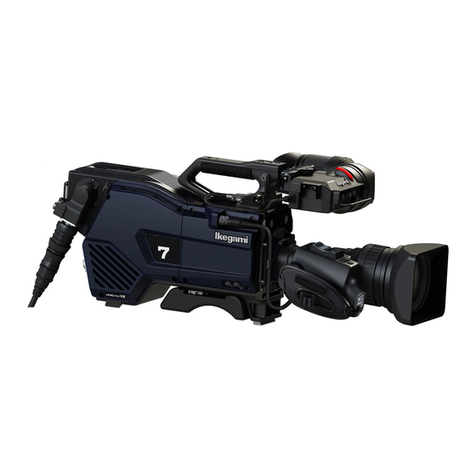
Ikegami UHL-43 User manual

Products conforming to RoHS directive
UHL-43
Multi Purpose Camera
OPERATION MANUAL

Copyright © 2020 Ikegami Tsushinki Co., Ltd.
We reserve the copyright on the software we create.
1RSDUWRIWKLVSXEOLFDWLRQPD\EHPRGL¿HGRUUHSURGXFHGLQDQ\IRUPRUE\DQ\PHDQVZLWKRXWSULRUZULWWHQSHUPLVVLRQIURP
Ikegami Tsushinki Co., Ltd.

PRODUCTS CONFORMING TO RoHS DIRECTIVE
i
UHL-43 2005 VER1 (E)
PRODUCTS CONFORMING TO RoHS DIRECTIVE
Following products described in this manual are products conforming to RoHS directive.
- UHL-43 Multi purpose Camera
MAINTENANCE OF PRODUCTS CONFORMING TO RoHS DIRECTIVE
Work with care about followings for maintenance of products conforming to RoHS directive.
1. Identification
- For products conforming to RoHS directive, the letter “E” is appended at the end of the serial number on the label. For models
that the letter cannot be appended to the serial number, the letter “E” will be described in a distinguishable position on the label.
A description example on a main label is shown below.
Product conforming to RoHS directiv
e
Label
MADE IN JAPAN
MADE IN JAPAN
SER No.
SER No.
MULTI PURPOSE CAMERA
UHL-43
AA123456E
THIS DEVICE COMPLIES WITH PART 15 OF THE
FCC RULES.OPERATIONS IS SUBJECT TO THE
FOLLOWING TWO CONDITIONS:(1) THIS DEVICE
MAY NOT CAUSE HARMFUL INTERFERENCE,AND(2)
THIS DEVICE MUST ACCEPT ANY INTERFERENCE
THAT MAY CAUSE UNDESIRED OPERATION.
- The printed circuit boards of the RoHS compliant products have ether of the following marks with serigraph or label.
Phase 3
Phase 3A
2. Soldering
Since the melting point of lead-free solder used for the products conforming to RoHS directive is 20 to 45 degrees Celsius higher
than that of conventional solder with lead (Sn-Pb eutectic solder), a high temperature needs to be set to a soldering iron. Taking
allowable temperature limit of the parts and stable work into consideration, use a soldering iron with excellent thermal recovery
characteristics.
- Recommended solder composition is “Sn/3.0Ag/0.5Cu” or equivalent.
- Separate the soldering iron exclusively for RoHS products and the soldering iron for conventional use.
- Set the temperature of the soldering bit to 350 to 370 degrees Celsius.
The temperature may need to be adjusted according to the size of the copper foil land on the print-circuit board and the tip width
of the soldering bit.
- Finish by a lead-free solder looks dull or whitish compared to conventional solder with lead.
- If the customer mixed the lead-solder with the main body wiring or the circuit board, it becomes guarantee off the subject.
Ikegami doesn't guarantee to do the repair work. Because the solder polluted with lead cannot be removed.
3. Parts
Be sure to use parts conforming to RoHS directive.

ii UHL-43 2005 VER1 (E)
INFORMATION TO THE USER
1. This equipment has been tested and found to comply with the limits for a Class A digital device, pursuant to Part 15 of the FCC
Rules. These limits are designed to provide reasonable protection against harmful interference when the equipment is operated
in a commercial environment. This equipment generates, uses, and can radiate radio frequency energy and, if not installed and
used in accordance with the instruction manual, may cause harmful interference to radio communications.
Operation of this equipment in a residential area is likely to cause harmful interference in which case the user will be required to
correct the interference at his own expense.
&KDQJHVRUPRGL¿FDWLRQVQRWH[SUHVVO\DSSURYHGE\WKHSDUW\UHVSRQVLEOHIRUFRPSOLDQFHFRXOGYRLGWKHXVHUVDXWKRULW\WR
operate the equipment.
This device complies with Part 15 of the FCC rules.
Operation is subject to the following two conditions:
(1) This device may out cause harmful interference, and
(2) This device must accept any interference received, including interference that may cause undesired operation.
Supplier's Declaration of Conformity
47 CFR § 2.1077 Compliance Information
Product Name : Multi Purpose Camera
Model Name : UHL-43
Responsible Party : Contact Information
Ikegami Electronics (U. S. A.) Inc
300 Route 17 South, Mahwah, NJ 07430, USA
Tel : 201-368-9171
2. Declaration of conformity
The CE mark means that the following products will meet and the Standards EN55032, EN-55035.
For European customer.
People’s Republic of China Electronic Industry Standard (SJ/T11364—2006)
Marking Styles for Names and Contents of Toxic or hazardous Substances and Elements
Part Name
Toxic or hazardous Substances and Elements
Lead
(Pb)
Mercury
(Hg)
Cadmium
(Cd)
Hexavalent
Chromium
(Cr/(VI))
Polybrominated
biphenyls
(PBB)
Polybrominated
diphenyl ethers
(PBDE)
UHL-43 × żżżżż
ż,QGLFDWHVWKDWWKLVWR[LFRUKD]DUGRXVVXEVWDQFHFRQWDLQHGLQDOORIWKHKRPRJHQHRXVPDWHULDOVIRUWKLVSDUWLVEHORZWKHOLPLW
requirement in SJ/T11363-2006.
×: Indicates that this toxic or hazardous substance contained in at least one of the homogeneous materials used for this part is
above the limit requirement in SJ/T11363-2006.

iii
UHL-43 2005 VER1 (E)
SAFETY PRECAUTIONS
SAFETY PRECAUTIONS
SAFETY PRECAUTIONS
This manual describes the precautions using various pictorial symbols for you to use the product safely. Please read these
precautions thoroughly before use. The symbols and meanings are as follows:
The following hazard alert symbols are used to indicate the level of impact on the body or property
when you do not follow the precautions.
Indicates that mishandling of the product by ignoring this label may lead to a danger resulting in a
serious injury or death.
Indicates that mishandling of the product by ignoring this label may lead to a danger resulting in an
injury or property damage.
The following symbols are used to indicate the expected injury or hazards when you do not follow
the precautions.
Indicates general cautions on such matters as safe work, procedure, and installation location. Mishandling
may not directly lead to death, injury, or property damage.
Indicates that mishandling may cause an electric shock.
,QGLFDWHVWKDWPLVKDQGOLQJPD\FDXVHD¿UH
Indicates that mishandling may cause injury.
The following symbol is used to indicate other precautions to prevent damage or hazard from
occurring:
Indicates prohibited action.

iv UHL-43 2005 VER1 (E)
SAFETY PRECAUTIONS
---
Handling Precautions
Regarding the Product
Do not disassemble or modify the product which is not described in this manual. Doing so may
FDXVH¿UHHOHFWULFVKRFNRULQMXU\
Regarding the Product
Do not lift or hold the camera by the projection parts.
,I\RXOLIWRUKROGWKHFDPHUDE\WKHYLHZ¿QGHURUWKHOHQV\RXDUHSURQHWRGURSSLQJLW0RUHRYHU
WKHFRQQHFWLRQSDUWVEHWZHHQWKHFDPHUDDQGWKHYLHZ¿QGHURUWKHFDPHUDDQGWKHOHQVPD\EH
exposed to unnecessary pressure, which may cause equipment damage.
$OZD\VLQVWDOOWKHDFFHVVRULHVRUFRQQHFWWKHFDEOHVDIWHUSODFLQJWKHFDPHUDRQD¿[HGSRVLWLRQ
:KHQLQVWDOOLQJVXFKDFFHVVRULHVDVOHQVRUPLFURSKRQH¿[WKHFDPHUDRQDVWDEOHSODFHHJRQD
table, a tripod, etc.).
Avoid use or storage in the following conditions:
- Extremely high/low temperature
- In direct sunlight for a long time, or near a heater
- High humidity or dusty
- Exposed to water or other liquid
- Strong vibration or shock
6WURQJPDJQHWLF¿HOGRUUDGLRZDYHV
- lightning
- In rain without the rain cover
Regarding the Product
Be sure to hold the plug and pull when you disconnect the cable.
)DLOXUHWRGRVRPD\FDXVHD¿UHRUHOHFWULFVKRFNGXHWRDEURNHQFDEOH
Avoid moving the equipment suddenly from an extremely cold place to a warm place.
Condensation may occur in the optical block or other area of the camera.
Do not drop or insert a metal object such as a pin or a foreign object into the equipment.
Do not spread or spill water or other liquid on the equipment.
Do not subject the equipment to a strong shock or vibration.
Doing so may cause damage or malfunction of the equipment.
Since CMOS sensors are element is adopted as the imagers sensor in picture elements, no burning
occurs in ordinary operation. However, when shooting a subject which emits an excessive amount
of light (Sun, laser light, etc.) for long hours, take great care for temperature increase inside of the
sensors.
Laser beams may damage the sensors. If you shoot a scene that includes a laser beam, be careful
not to let a laser beam become directed into the lens of the camera.
Before connecting an accessories, make sure that the camera and equipment to be connected are
powered off. Also, be sure to use dedicated cables.
Excessive sound pressure from the headset may cause a hearing loss.

v
UHL-43 2005 VER1 (E)
SAFETY PRECAUTIONS
Regarding the Power and the Lithium Battery
Use the product in compliance with the rating of the fuse within the product and that within the
product. Otherwise, a fault can occur.
'RQRWXVHDQXQVSHFL¿HGEDWWHU\
:URQJXVDJHRIEDWWHULHVPD\FDXVHOLTXLGOHDNH[SORVLRQDQGKHDWDQGDWZRUVWLQMXU\RU¿UH
When changing or discarding a battery, please contact Ikegami’s sales and service centers.
Risk of explosion if battery is replaced by an incorrect type. Dispose of used batteries according to
the instructions.
---
Environmental Cautions
Regarding the product
When continuously operating the product in a rainy, cold or hot conditions, use a rain cover, cold-
weather cover, and shade cover respectively.
Avoid storing the product in a dusty place for a long time. If unavoidable, use a dustproof cover.
When shooting in places such as airports, military bases or transmitting stations where magnetic
DQGUDGLR¿HOGVDUHH[FHVVLYHO\VWURQJFRPSOHWHO\VKLHOGWKHFDPHUDE\FRYHULQJLWZLWKDOXPLQXP
foil.
---
Maintenance
Regarding the product
Before performing maintenance on the product, be sure to turn off the power for safety and for
protection against malfunction.
Clean the product using a dry and soft cloth.
If the stain is hard, soak the cloth with water or detergent, wring well and wipe. If you use
detergent, wipe off the detergent with a cloth that is soaked in just water and wrung well.
---
Notice for Use
- When carrying or storing the product, always use a carrying case.
- Before shooting important subjects, take test shots to obtain the desired effect.
- After using the product, always turn off the power.
---
Regular Maintenance Recommended
This product includes parts that wear out and have a limited life even in proper use or storage. Therefore, regular maintenance is
recommended to extend the life and safe use of this product for a long time. Please contact Ikegami’s sales and service centers for
the regular maintenance and repair of our products.

vi UHL-43 2005 VER1 (E)
HOW TO READ THE OPERATION MANUAL
This page explains general notes on reading the UHL-43 Operation Manual, and the symbols and notations used in the manual.
---
Notes on the Manual
- This manual is written for readers with a basic knowledge of handling broadcast cameras.
- The contents of this manual are subject to change without notice in the future.
---
Symbols
The symbols used in this manual are as follows:
CAUTION: Things you have to be careful during operation. Be sure to read.
Note: Supplementary information or guidance
Reference: Sections where related information is available
---
Notations
The following notations are used in this manual.
This product, Camera Indicates UHL-43.
OCP Basically indicates OCP-300 Operation Control Panel.
MCP Basically indicates MCP-300 Maintenance Control Panel.
“ ” - “ ” - “ ” Indicates the items enclosed by double quotes (“ ”) are to be selected
DQGFRQ¿UPHGLQWKHRUGHUVKRZQ
4K 4K indicates the video outputs with active image area of 3840 x 2160
or 4096 x 2160. In this document, 4K indicates the 3840 x 2160 output.
HD (SDI) Signals that comply with SMPTE 292 1.5Gb/s Signal/Data Serial
Interface 1280×720, 1920 x 1080.
3G (SDI) Signals that comply with SMPTE 424/425 3Gb/s Signal/Data Serial
Interface 1920×1080 (Level-A/B).
Quad Link A method to construct a 4K image with 4 links.
---
Illustrations and Displays
The illustrations and displays in the text are provided for explanation and may be slightly different from the actual equipment or
image.
---
Related Manuals
Please refer to Operation Manual and Maintenance Manual of each product.

vii
UHL-43 2005 VER1 (E)
HOW TO READ THE OPERATION MANUAL
Chapter 1 OUTLINE
Explains the features and the main operating systems of this product.
If you are not familiar with UHL-43 Camera System, please start with this chapter.
Chapter 2 NAME and FUNCTION
Explains the name and function of each part of the Camera.
Chapter 3 INSTALLATION and CONNECTION
This chapter explains the installation method of this product and lenses, etc.
And examples how to connect this product to the peripheral equipment.
Chapter 4 OPERATION
Explains the setup required before shooting.
%HIRUHVKRRWLQJIRUWKH¿UVWWLPHUHDGWKLVFKDSWHUDQGFKHFNWKDWWKLVSURGXFWLVRSHUDWLQJQRUPDOO\
Chapter 5 CAMERA SETTINGS and ADJUSTMENT
This product realizes detailed settings to support a wide range of operations and various video
expressions through the menu window. This chapter explains the settings through the menu screen.
Chaprter 6 TROUBLE SHOOTING and MAINTENANCE
When the alarm lamp lights during the operation of this product, read here to know the problem. This
chapter also explains the regular maintenance.
Chapter 7 SPECIFICATIONS
([SODLQVWKHVSHFL¿FDWLRQVRIWKLVSURGXFW
CHANGING INFORMATION
&RQWDLQVUHYLVLRQLQIRUPDWLRQRIGHVLJQUHYLVLRQRUFXVWRPHUVSHFL¿FVSHFL¿FDWLRQUHTXHVWHG
by customers. Read by comparing with the main text of the operation manual. (“CHANGING
INFORMATION” may be sent to you later on.)
---
Structure of Operation Manual
This manual is intended to help you operate the UHL-43 safely and smoothly. This manual consists of seven chapters. We
recommend you read them in sequence from Chapter 1 to Chapter 7 so that you can carry out all the work smoothly through the
installation to the operation of the camera equipment.

viii UHL-43 2005 VER1 (E)
CONTENTS
UHL-43
Multi Purpose Camera
OPERATION MANUAL
PRODUCTS CONFORMING TO RoHS DIRECTIVE. . . i
MAINTENANCE OF PRODUCTS CONFORMING TO
RoHSDIRECTIVE.............................. i
INFORMATIONTOTHEUSER ...................ii
SAFETYPRECAUTIONS....................... iii
HOWTOREADTHEOPERATIONMANUAL....... vi
Chapter 1 OUTLINE
1.1
Outline...............................1
1.2 Features............................. 1
Chapter 2 NAME and FUNCTION
2.1
RightSide............................2
2.2 Rightsideofthehandle(Option)......... 2
2.3 Front side............................ 3
2.4 Rearside............................ 5
2.5 Bottomside.......................... 6
Chapter 3 INSTALLATION and CONNECTION
3.1 Preparation.......................... 7
3.2 MountingthecameraontheTripod ...... 7
3.3 LensAttachment...................... 7
3.4 Powersupplyconnection............... 8
3.5 ConnectingtheRemoteController....... 8
3.6 ConnectingaMonitor.................. 8
3.7 GENLOCKSystem .................... 8
Chapter 4 Operation
4.1 Turning ON Power .................... 10
4.2 Checkingtheoutputsignal ............ 10
4.3 Executing automatic setup ............ 10
4.4 AdjustingtheLens ....................11
Chapter 5 Camera Setting and Adjustment
5.1
BasicOperationoftheMenu........... 13
5.2 Menustructuresandcontents.......... 16
5.3 Creationofalensfile................. 35
5.4 UsingtheUSBmemory ............... 38
5.5 Allocation of functions to
FUNCTIONswitches.................. 41
5.6 DisplaysintheViewfinder ............. 42
Chapter 6
Troubleshooting
Troubleshooting
6.1 When the STATUS indicator lights red . . . 44
6.2 Initializing the settings of this camera.... 44
6.3 Fuse replacement .................... 46
Chapter 7 Specification
7.1 Productspecification................. 47
CHANGINGINFORMATION.....................50

1 OUTLINE
1
UHL-43 2005 VER1 (E)
Chapter 1 OUTLINE
1.1
Outline
7KH8+/LVDRQHSLHFHQDWLYH.8OWUD+LJK'H¿QLWLRQ
Digital Multi Purpose Camera, employing the same sensors
as the UHK-430/435 "UNICAM XE" series cameras, and
achieving the same performance.
7KHFDPHUDSURYLGHVWKHVDPHRSHUDWLRQDQGVDPHZRUNÀRZ
as the UHK-430/435 system cameras, and due to its compact
one-piece form factor, it supports various POV applications
VXFKDVÀDVKDQGVWXGLRURERWLFFDPHUDMLEDQG6WHDGLFDP
FDPHUDWUDI¿FDQGZHDWKHUFDPHUDVFRUHERDUGFDPHUDDV
well as, a wide range of surveillance applications.
Moreover, the camera provides various kinds of 4K main
output including 12G-SDI and Quad Link 3G-SDI, realizing
ÀH[LEOH.V\VWHPLQWHJUDWLRQ
1.2 Features
---
Real 4K Resolution using 2/3-inch
Native 4K CMOS Sensors
The UHL-43 utilizes three 2/3-inch 8 megapixel CMOS
sensors, each capable of capturing native 4K 3840 x 2160
resolution images.
It offers an excellent sensitivity of F10 (in 4K/59.94p) and a
remarkable signal-to-noise ratio.
Unlike single chip cameras or cameras using pixel-offset
technology, three native 4K CMOS sensors and prism optics
provide real 4K resolution, superior color reproduction and no
color aliasing.
---
HDR (High Dynamic Range) mode
The UHL-43 provides an HLG (Hybrid Log Gamma) mode,
conforming to ITU-R BT.2100 which is an international
standard for HDR. It is now possible to expand the range
represented from dark to bright, providing superb bright
pictures with High Dynamic Range, and also achieve rich
colors with wide color gumut.
---
Lens chromatic aberration correction
The UHL-43 acquires correction data from serial digital
lenses and automatically corrects lens chromatic aberration
based on lens zoom, focus, and iris position information.
---
Various output interfaces
HD output is supported as a standard output. 4K outputs
(12G SDI, QUAD LINK, and 12G Optical) are supported as
options.
---
Various configurations
An optional kit is available to convert this box camera for
KDQGKHOGRSHUDWLRQZLWKWRSKDQGOHLQFKYLHZ¿QGHUHWF
---
Ethernet connection supported
Remote control by Ethernet connection is available as
standard.
In addition to the Ethernet connection, conventional Ikegami
serial command (ICCP) is available as an option.
---
Indicators
The UHL-43 provides tally and camera number (2 digit) on
the front side, and tally on the rear side, increasing visibility.
---
Enhanced Maintenance
Maintenance is enhanced by logging camera information. In
DGGLWLRQXSGDWLQJWKH¿UPZDUHRIHDFKPRGXOHLVDYDLODEOH
from the USB port at the rear side of the camera.

2 NAME and FUNCTION
2UHL-43 2005 VER1 (E)
Chapter 2 NAME and FUNCTION
This section explains the names and functions of the controls
and connectors on the camera.
2.1
Right Side
1
2
3
4
5
(1) UP/DOWN switches
To adjust the assigned item. For the assigned items, refer to
"Chapter 5 Camera Setting and Adjustment."
(2) MENU Rotary Encoder (RE)
The USER MENU screen is displayed by pressing this RE.
Turn the RE to select the operation you wish to use from
the menu items displayed on the screen, and press this RE
to select. The contents of the menu and setting methods are
explained in "Chapter 5 : CAMERA SETTINGS and
ADJUSTMENT".
(3) F1 (Function 1)/F2 (Function 2) switches
Select one of the items available using the menu, and assign it
to F1 or F2 switch.
Please refer to "Chapter 5 : CAMERA SETTINGS and
ADJUSTMENT" for assigning items and method.
(4) CHAR switch
The character display on the VF video (Monitor output)
GLVSOD\VLQIRUPDWLRQFKDUDFWHUVXVHGWRFRQ¿UPWKHVWDWXV
of various controls of the camera. Pressing the CHAR switch
ZLOOFDOOXSWKHIXOOFKDUDFWHUGLVSOD\RQWKHYLHZ¿QGHUYLGHR
This is also used to call up the MENU by pressing the MENU
RE simultaneously.
(5) STATUS/POWER Indicator
Displays the status of power supply condition to the camera.
Green light: Power is supplied.
Red light : Warning indication.
Caution
Check the warning contents and handle appropriately.
For the explanation of warnings, refer to "Chapter 6
Troubleshooting."
2.2 Right side of the
handle (Option)
6
7
1
2 3
4
8
5
(1) Handle
7RKROGWKHFDPHUDRUWRXVHYLHZ¿QGHU
This is an optional handle.
(2) D-TAP connector
A power output connector (DC +12V 1.5A) that supplies
power to external compact monitors, etc.
This is on the optional handle.
Camera side: D-Tap CN BASE
Cable side: D-Tap connector (male)
Pin No. Name Function I/O
①+12V DC +12V power supply OUT
②+12V_RET Ground for DC+12V power supply GND
(3) F3 (Function 3)/F4 (Function 4) switches
Select one of the items available using the menu, and assign it
to F3 or F4 switch.
This is on the optional handle.
Please refer to "Chapter 5 : CAMERA SETTINGS and
ADJUSTMENT" for assigning items and method.
(4) VF lock mount
7RPRXQWDSRUWDEOHYLHZ¿QGHU
This is on the optional handle.
(5) VF lock ring
7RORFNWKHYLHZ¿QGHUDIWHUDGMXVWLQJOHIWULJKWSRVLWLRQ
This is on the optional handle.
(6) VF front-back lock lever
7RORFNWKHYLHZ¿QGHUDIWHUDGMXVWLQJIURQWEDFNSRVLWLRQ
This is on the optional handle.

2 NAME and FUNCTION
3
UHL-43 2005 VER1 (E)
(7) VF connector
&RQQHFWWKHYLHZ¿QGHUFDEOH
This is on the optional handle.
1 2 3 4 5 6 7 8 9 10 11 12 13
14 15 16 18 19 20 21 22 23 24 25 2617
Receptacle
Insertion Side
Receptacle
Camera side: HDR-EA26LMYPG1-SLE+
Cable side: HDR-EA26FAG1+
Pin
No. Name Function I/O
1
GND Ground for DC+12V power supply GND
14
GND Ground for DC+12V power supply GND
2
GND Ground for DC+12V power supply GND
15
GND Ground for DC+12V power supply GND
3
+12V DC +12V power supply OUT
16
+12V DC +12V power supply OUT
4
+12V DC +12V power supply OUT
17
+12V DC +12V power supply OUT
5
RS422_RX+
Serial control signal (P) (VF -> Camera) IN
18
RS422_RX- Serial control signal (N) (VF -> Camera ) IN
6SIGNAL_GND
Ground for Serial control signal (VF -> Camera)
GND
19
IKEGAMI_VF
IKEGAMI VF connection control signal IN
7
RS422_TX+
Serial control signal (P) (Camera -> VF)
OUT
20
RS422_TX-
Serial control signal (N) (Camera -> VF)
OUT
8SIGNAL_GND
Ground for Serial control signal (Camera -> VF)
GND
21
N C ---- ----
9
N C ---- ----
22
R TALLY R TALLY signal OUT
10
G TALLY G TALLY signal OUT
23
Y TALLY Y TALLY signal OUT
11
N C ---- O U T
24 SIGNAL_GND
GND GND
12
SDI+ Serial video signal + (HD SDI) OUT
25
SDI- Serial video signal - (HD SDI) OUT
13 SIGNAL_GND
GND GND
26 SIGNAL_GND
GND GND
(8) VF offset plate (option)
,WORZHUVWKHKHLJKWRIYLHZ¿QGHUDWWDFKPHQWWRWKHRSWLRQDO
handle.
2.3 Front side
6
1
2
7
8
3
4
5
(1) LENS connector
Connect the lens cable (12 pins).
Insertion Side
㻟
㻞
㻝㻥
㻝㻜
㻤
㻝㻝㻝㻞
㻣
㻢 㻠
㻡
Camera side : HR10A-10R-12SC
Cable side : HR10A-10P-12PC (12-pin male plug)
Pin
No. Name Function I/O
①RET ON
RETURN VIDEO ON/OFF signal
RETURN ON: 0.5V or less Zout =
0ȍRUPRUH
RETURN OFF: OPEN Zout = 1.5k
ȍRUOHVV
=LQ NȍNȍRUPRUH
Momentary operation
IN
②VTR TRIG
VTR START/STOP signal
VTR START: 0.5V or less Zout =
0ȍRUPRUH
975672323(1=RXW Nȍ
or less
=LQ NȍNȍRUPRUH
Momentary operation
IN
③GND Grounding for LENS GND
④IRIS SERVO
Forced IRIS servo ON/OFF
6(59221 99
=RXW NȍRUOHVV
SERVO OFF : 0.5V or less
=RXW NȍRUOHVV
RUNȍRUPRUH 上
OUT
⑤IRIS CONT
Control output of lens iris
) 99
99
) 99
99
&/26( 99
(2.1V to 2.9V)
=RXW Nȍ)L[HG
OUT
⑥+12V LENS
DC+12V output for LENS
Normal operation range: D C +1 0V
- +20V
(DC+10V - +17V)
OUT

2 NAME and FUNCTION
4UHL-43 2005 VER1 (E)
Pin
No. Name Function I/O
⑦IRIS FOLLOW
Control output of lens iris
) 99
99
) 99
99
&/26( 99
(2.1V to 2.9V)
=LQ Nȍ N ȍ RU
more)
IN
⑧IRIS REM/AUTO
Switching between REMOTE/
AUTO of IRIS
5(027( 99
=RXW N ȍ Nȍ RU
less)
AUTO : 0.5V or less
=RXW NȍRUOHVV
RUNȍRUPRUH
=LQ NȍNȍRUOHVV
OUT
⑨EXT ANS
Input/output of answer signals from
the external system
,1 9ȍRUOHVV=RXW N
ȍRUOHVV
287 23(1 =RXW 0ȍ RU
more
=LQ NȍNȍRUPRUH
IN
⑩ZOOM FOLLOW
Control output of lens zoom
:,'( 99
99
7(/( 99
99
=LQ NȍNȍRUPRUH
=RXW NȍNȍRUOHVV
IN
⑪
6(5,$//(16ĺ
CAMERA
/FOCUS FOLLOW
Serial data reception (LENS --->
CAMERA)
+0.5V CMOS level
9&&99
Control output of lens focus
&ORVHHQG99
99
,Q¿QLWHHQG99
99
=LQ NȍNȍRUPRUH
=RXW NȍNȍRUOHVV
OUT
⑫6(5,$/&$0(5$ĺ
LENS
Serial data transmission (CAMERA
---> LENS)
+0.5V CMOS level
9&&99
OUT
(The values indicated in ( ) are standard values in 2/3"
Camera/Lens.
IN : Camera <--- Lens
OUT : Camera ---> Lens
(2) MIC connector
To connect a microphone or to input a line level audio signal.
12
3
Plug receptacle HA16PRM-3S (05)
Pin No. Name
①Shield
②Hot
③Cold
Refer to "Chapter 5 Camera Setting and Adjustment"
for the power to the microphone and the settings such as input
level adjustment.
(3) FRONT TALLY lamp
Lights up red when the R TALLY signal is input. Refer to
"Chapter 5 Camera Setting and Adjustment" to
adjust the brightness or turn off.
(4) Camera number indicator
Indication area of the assigned camera number. Refer to
"Chapter 5 Camera Setting and Adjustment" to
assign the camera number.
(5) Emergency manual optical filter control
)RUHPHUJHQF\WRURWDWH¿OWHUGLVFE\VFUHZGULYHU5HPRYH
UXEEHUFDSDQGWXUQXVLQJDÀDWKHDGVFUHZGULYHU
Caution
Turn off the power before adjusting or set FILTER SERVO
CONT to MANUAL from the Menu to prevent damage to
the motor drive.
Caution
Keep the rubber cap after adjusting to protect against dust
entering the camera.
(6) Lens cable clamp
Clamp the lens cable.
(7) Lens lock lever
A lever used to lock the lens mount. Insert the lens, and then
turn and tighten the lens mount ring with the lever.
(8) Lens mount
Various 2/3-inch broadcast lenses can be used.

2 NAME and FUNCTION
5
UHL-43 2005 VER1 (E)
2.4 Rear side
6
1
2
1
11
8
3
4
5
7
(1) REAR TALLY lamp
Lights up red or green when the R TALLY signal or G TALLY
signal is input. Refer to "Chapter 5 Camera Setting and
Adjustment" to adjust the brightness or turn off.
(2) I/O connector
Input TALLY IN signals and output TALLY OUT for external
interface.
1
2
3
456
7
8
109
Receptacle HR10A-10R-10SC(71)
Pin
No. Name Function External Interface
①TXD_P Output for PC
Reserved for factory use
②TXD_N Output for PC
③RXD_P Input for PC
④RXD_N Input for PC
⑤GND
⑥
or
+V
⑦
⑧
⑤
⑦
⑧
⑥UNREG_OUT DC11-17V
500 mA MAX
⑦R_TALLY_OUT Red tally control
output
⑧G_TALLY_OUT Green tally control
output
⑨R_TALLY_IN Red tally control
input
⑩G_TALLY_IN Green tally control
input
(3) GL IN/SYNC OUT connector
Synchronization signal (HDTV tri-level SYNC or SDTV VBS/
BBS) is input to synchronize the camera.
Synchronization signal (Tri-level sync) can be output by setting
in the MENU.
(4) Fan motor
Fan motor to cool inside of the camera.
Caution
Do not block the exhaust port. Otherwise, the temperature
inside the camera increases, and serious damage to the camera
can occur.
(5) QUAD LINK (option)
Connector panel to output 4 lines of 3G/HD-SDI signal. QUAD
Link 4K signal can be output when operating in an optional 4K
format.
(6) USB connector
Connect a USB memory drive to save or load a settings data
¿OH
Refer to "Chapter 5 Camera Setting and Adjustment"
for detail.
(7) 12G-SDI fiber link (option)
Connector for optical Main output and RET input signals to
extend the transmission distance.
The control signal is not included.
Prepare external LAN cable for control.
(8) LAN connector (Ethernet RJ45 (8P8C)
Connects a network compatible remote controller via a PoE+
supported switch.
(8) REMOTE connector (option)
An optional connector to connect a serial data remote
controller using a CP cable.
Insertion Side
H
Camera side : PRC05-R8F
Cable side : PRC05-PB8M
Pin
No.
Name Function I/O
ⒶHED (+)
Digital data output (+) from camera to
remote
controller
OUT
ⒷHED (-)
Digital data output (-) from camera to
remote
controller
OUT
ⒸHEC (+)
Digital data input (+) from remote
controller to
camera
IN
ⒹHEC (-)
Digital data input (-) from remote
controller to
camera
IN
ⒺMU_REAR+12V DC+12V power supply (max. 2.0A) OUT
ⒻDGND Ground for DC+12V power supply OUT
ⒼRESERVE
ⒽRESERVE

2 NAME and FUNCTION
6UHL-43 2005 VER1 (E)
(9) SDI connector
Output 3G/HD-SDI Main signal.
12G-SDI signal can be output when operating in an optional 4K
format.
(10) MONITOR connector
The characters such as MENU are superimposed. VF signal
can be output by selecting in the MENU. Refer to "Chapter 5
Camera Setting and Adjustment" for details.
(11) DC IN connector
DC+12V input connector to connect to the AC Adapter to
supply power to the camera.
4
Plug receptacle XLR-4-32-F512
Pin No. Name
①+DC12V-RET (GND)
②NC
③NC
④DC+12V (+12V IN)
2.5 Bottom side
1
2
(1) Camera mounting screw (3/8-16UNC)
To mount the camera to the tripod. It supports 3/8-16UNC
screws (7 mm or shorter in length).
(2) Camera mounting screw (1/4-20UNC)
To mount the camera to the tripod. It supports 1/4-20UNC
screws (6 mm or shorter in length).

3 INSTALLATION and CONNECTION
7
UHL-43 2005 VER1 (E)
Chapter 3
INSTALLATION and
CONNECTION
3.1 Preparation
---
Operating environment
Please read “SAFETY PRECAUTIONS” described at
the beginning of this manual for precautions on use of this
product.
---
Make sure the Power Switch of AC
Adapter is OFF.
This product does not have a power switch. Be sure the Power
switch of AC Adapter is turned off before connecting this
product.
3.2 Mounting the
camera on the Tripod
Attach the camera to the tripod.
1
Align a tripod mounting hole of the camera to
WKHFDPHUD¿[LQJVFUHZRIWKHWULSRG
Tripod mounting hole
Tripod
Bottom side
Camera fixing screw
Caution
The camera has two types of mounting holes. Check the
screw size at the tripod side.
- Camera mounting screw (3/8-16UNC)
- Camera mounting screw (1/4-20UNC)
2
Tighten the camera fixing screw to fix the
camera to the tripod.
3.3 Lens Attachment
Attach the lens to the camera.
When attaching the lens, place the camera on the tripod or on
a horizontal and stable surface.
Note
The lens mount of the camera supports the BTA mount
method.
1
Raise the lens lock lever to remove the lens
cap.
2
Align the lens pin and the notch of the camera
lens mount and insert horizontally.
At this time, hold with hand in order to prevent
dropping the lens.
3
Fix the lens to the camera.
/RZHUWKHOHQVORFNOHYHUDQG¿[WKHOHQVWRWKH
camera.
3 Push down the Lens lock
lever to secure the lens.
2 Align and insert it into the notch.
4
Connect the pigtail cable to the lens connector.
When the pigtail cable is pressed in with the
connector pin aligned, it is automatically locked.
Note
Do not turn to lock or unlock.
5
Fix the pigtail cable to the cable clamp so it
does not get loose.
Caution
Avoid carrying the camera by holding the lens housing
only. Applying excessive force to the lens mount can cause
damage.

3 INSTALLATION and CONNECTION
8UHL-43 2005 VER1 (E)
4 Connect the pigtail cable.
5 Secure it to the cable clamp.
3.4
Power supply connection
The power supply voltage to the camera is DC+12V. In
addition, the allowable range is DC11 to 17V.
Caution
Do not use an AC Adapter with output out of range. The
camera may have serious damage.
This product does not have a power switch. Be sure the
Power switch of AC Adapter is turned off before connecting
this product.
1
Confirm that the power supply switch of the AC
adapter is OFF.
2
Connect the DC cable to the DC OUT
connector of the AC adapter.
3
Connect the DC cable to the DC IN connector
on the camera.
4
Turn the power switch of the AC adapter to ON
to supply power to the camera.
(When the power is supplied, the camera STATUS
indicator turns Green on.)
AC Adapter
DC POWER Cable
DC IN Connector
DC OUT
Connector
POWER
Switch
Camera rear side
3.5 Connecting the
Remote Controller
Connect the LAN connector at the camera rear side and the
connector for LAN of the Remote control panel (OCP-300)
which can be controlled by the network connection via the
PoE+ (IEEE 802.3at)-supported network switch.
AC Adapter
Camera
LAN Cable LAN Cable
REMOTE option
CP Cable
Connecting of
COMMAND Connector
OCP-300
Connecting to
LAN Connector
Network switch
(with PoE+)
Note
The REMOTE (option) is necessary to use a conventional CP
cable.
3.6 Connecting a Monitor
Connect a monitor which has an HD-SDI input to the
MONITOR connector on the camera using a coaxial cable.
The output signal can be changed from the menu. The default
setting is 1080i59.94 format.
H LM905W C S H D
Coaxial
cable
SDI Input
Monitor
output Monitor
3.7 GENLOCK System
This section explains the input signal and output signal of the
GENLOCK system of this product.
---
Input synchronous signal
The output video signals can be locked to a standard
synchronization signal input to the GL IN/SYNC OUT
connector. The phase between the output video signals and
standard synchronization signal can be adjusted in horizontal
and vertical from the Menu.
Two types of signals can be input to the GL IN/SYNC OUT
connector:
- HDTV PS/S (tri-level sync)
- SDTV VBS/BBS (NTSC/PAL)
When switching between the input and output of the GL IN/
SYNC OUT connector and for phase adjustment of the output
video signal and the reference synchronous signal, refer to
"Chapter 5 Camera setting and adjustment".

3 INSTALLATION and CONNECTION
9
UHL-43 2005 VER1 (E)
---
Output synchronous signal
The GL IN/SYNC OUT connector can be switched to an output
connector for the synchronization signal. The phase between
the output video signals and the output synchronization signals
are the same.
Note
The output synchronization signal is TRI-LEVEL SYNC only.

4 Operation
10 UHL-43 2005 VER1 (E)
Chapter 4 Operation
4.1 Turning ON Power
After connecting with the peripheral equipment, turn on the
power. This device does not have a power supply switch. It is
turned on by operating the POWER switch of the connected
AC adapter, etc.
Caution
When connectingor disconnecting the peripheral equipment,
be sure that the POWER switch of the AC adapter is "OFF."
AC Adapter
DC POWER Cable
DC IN Connector
DC OUT
Connector
POWER
Switch
Camera rear side
4.2
Checking the output signal
After turning ON the power, make sure the video signal is
properly output by checking the monitor connected to the
MONITOR connector.
H LM905W C S H D
Coaxial
cable
SDI Input
Monitor
output Monitor
4.3
Executing automatic setup
The camera is equipped with an auto setup function that
automatically adjusts various levels and settings using the
CPU of the camera.
---
Auto Setup function
(1) FULL auto setup
Executes all auto setup items in the camera. This is mainly
executed after maintenance and inspection. The auto setup
chart is required.
(2) LEVEL auto setup
Set the video processing levels. This process can be executed
daily before using the camera. The auto setup chart is
required.
(3) FULL QUICK auto setup
Because the FULL QUICK auto setup uses an electrical test
pulse signal built in the camera, you do not need an external
chart. Setup is possible even when you cannot shoot a chart.
(4) QUICK auto setup
Because the QUICK auto setup uses a test pulse, the setup
does not include adjustment of some circuits, CMOS sensors,
lens, etc. which are in the path prior to the point of injection
of the test signal.
(5) Auto White Balance (AWB)
Sets the white level of the R and B signals. White balance
needs to be readjusted when the color temperature of the
OLJKWVRXUFHFKDQJHVRURSWLFDO¿OWHUVDUHFKDQJHGEHFDXVH
white balance is affected by the color temperature of the light
VRXUFHDQGE\RSWLFDO¿OWHUV
(6) Auto Black Balance (ABB)
Sets the black level of the R, G and B signals. Though black
balance is affected neither by the color temperature of the
OLJKWVRXUFHQRUE\RSWLFDO¿OWHUVLWQHHGVWREHUHDGMXVWHG
when GAIN is changed or the ambient temperature has
FKDQJHGVLJQL¿FDQWO\
Note
$XWRVHWXSDGMXVWVWKHFDPHUDEDVHGRQDUHIHUHQFH¿OH7KLV
UHIHUHQFH¿OHLVFUHDWHGLQWKHPHPRU\SULRUWRVKLSPHQW7KH
UHIHUHQFH¿OHQHHGVWREHFUHDWHGDJDLQLI\RXZDQWWRFKDQJH
the reference for auto setup of the camera.
Auto setup can be activated from the camera or remote
controller. See the table in the next page for which functions
are adjusted by each auto setup process.
Table of contents
Other Ikegami Camcorder manuals

Ikegami
Ikegami HDK-725 User manual

Ikegami
Ikegami HDK-55 User manual

Ikegami
Ikegami Editcam 3 DNS-33W User manual

Ikegami
Ikegami HDK-790EXIII User manual

Ikegami
Ikegami HDK-790GX User manual

Ikegami
Ikegami HC-400 User manual

Ikegami
Ikegami CCU-430 User manual

Ikegami
Ikegami HL-DV7W User manual

Ikegami
Ikegami HDL-45E User manual

Ikegami
Ikegami HL-45A User manual