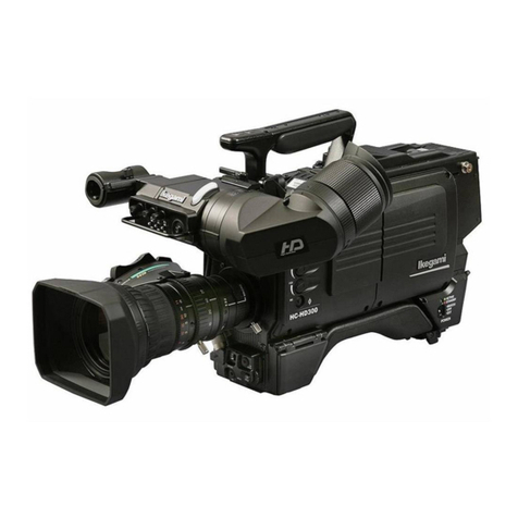
Ikegami HDL-45E User manual

HDL-45E/E1
3CCD Multiple-purpose HDTV Camera
Operation Manual
Products conforming to RoHS directive
3
4
2
4.1.6%
3.6.2%
2.25%
1.100%
NDFILTER
3
4
2
3
4
2
4.1.6%
3.6.2%
2.25%
1.100%
NDFILTER
3
4
2


1108 1st Edition (U) (E)
HDL-45E/E1
3CCD Multiple-purpose HDTV Camera
Operation Manual
Products conforming to RoHS directive
3
4
2
4.1.6%
3.6.2%
2.25%
1.100%
NDFILTER
3
4
2
3
4
2
4.1.6%
3.6.2%
2.25%
1.100%
NDFILTER
3
4
2

Copyright © 2011 Ikegami Tsushinki Co., Ltd.
We reserve the copyright on the software we create.
No part of this publication may be modified or reproduced in any form, or by any means, without prior written permission from
Ikegami Tsushinki Co., Ltd.

PRODUCTS CONFORMING TO RoHS DIRECTIVE i
Following products described in this manual are products conforming to RoHS directive.
・HDL-45E HDTV Camera
・HDL-45E1 HDTV Camera
Products conforming to RoHS directive include products that do not contain specified hazardous substances such as
lead, mercury, cadmium, hexavalent chromium, polybrominated biphenyl (PBB) and polybrominated diphenyl ether
(PBDE) in electrical and electronic equipment excluding following exemption applications based on the EU directive
(Directive2002/95/EC).
* About RoHS Directive
The RoHS directive stands for “the Restriction of the Use of Certain Hazardous Substances in Electrical and Electronic
Equipment” and is one of environmental directives in Europe. This directive restricts the use of specified hazardous
substances in electrical and electronic equipment.
●Applications exempted from RoHS directive compliance
Followings applications are permitted as exemptions from RoHS directive compliance.
1. Mercury in compact fluorescent lamps not exceeding 5mg per lamp
2. Mercury in straight fluorescent lamps for general purposes not exceeding:
・halophosphate 10mg
・triphosphate with a normal lifetime 5mg
・triphosphate with a long lifetime 8mg
3. Mercury in straight fluorescent lamps for special purposes
4. Mercury in other lamps not specifically mentioned in this Annex
5. Lead in the glass of cathode ray tubes, electronic components and fluorescent tubes
6. Lead as an alloying element in steel containing up to 0.35% lead by weight, aluminum containing up to 0.4% lead
by weight and as a copper alloy containing up to 4% lead by weight
7. Lead in following items
・Lead in high melting temperature type solders (i.e. tin-lead solder alloys containing more than 85% lead)
・Lead in solders for servers, storage and storage array systems
・Lead in solders for network infrastructure equipment for switching, signaling, transmission as well as network
management for telecommunication
・Lead in electronic ceramic parts (e.g. piezoelectronic devices)
8. Cadmium plating except for applications banned under Directive 91/338/EEC amending Directive 76/769/EEC
relating to restrictions on the marketing and use of certain dangerous substances and preparations
9. Hexavalent chromium as an anti-corrosion of the carbon steel cooling system in absorption refrigerators
10. Lead used in compliant pin connector systems
11. Lead as a coating material for the thermal conduction module C-ring
12. Lead and cadmium in optical and filter glass
13. Lead in solders consisting of more than two elements for the connection between the pins and the package of
microprocessors with a lead content of more than 80% and less than 85% by weight
14. Lead in solders to complete a viable electrical connection between semiconductor die and carrier within integrated
circuit Flip Chip packages
15. Decabrominated diphenyl ether (Deca-BDE) in polymeric applications
PRODUCTS CONFORMING TO RoHS DIRECTIVE

ii MAINTENANCE OF PRODUCTS CONFORMING TO RoHS DIRECTIVE
MAINTENANCE OF PRODUCTS CONFORMING TO RoHS DIRECTIVE
Work with care about followings for maintenance of products conforming to RoHS directive.
1. Identification
· For products conforming to RoHS directive, the letter “E” is appended at the end of the serial number on the
label. For models that the letter cannot be appended to the serial number, the letter “E” will be described in a
distinguishable position on the label. A description example on a main label is shown below.
MODEL HDL-45E
SERIALNo.
AA123456
E
Label
Product conforming to RoHS directive
· Print-circuit board of the products conforming to RoHS directive is manufactured by following methods.
[1] Blue resist ink is used for the print-circuit board. (The color of conventional print-circuit board is green.)
[2] Either one of the following marks is indicated by a serigraph or label.
Phase3A Phase3
2. Soldering
Since the melting point of lead-free solder used for the products conforming to RoHS directive is 20 to 45 degrees
Celsius higher than that of conventional solder with lead (Sn-Pb eutectic solder), a high temperature needs to be
set to a soldering iron. Taking allowable temperature limit of the parts and stable work into consideration, use a
soldering iron with excellent thermal recovery characteristics.
· Recommended solder composition is “Sn/3.0Ag/0.5Cu” or equivalent.
· Separate the soldering iron exclusively for RoHS products and the soldering iron for conventional use.
· Set the temperature of the soldering bit to 350 to 370 degrees Celsius.
· The temperature may need to be adjusted according to the size of the copper foil land on the print-circuit board
and the tip width of the soldering bit.
· Finish by a lead-free solder looks dull or whitish compared to conventional solder with lead.
· If the customer mixed the lead-solder with the main body wiring or the circuit board, it becomes guarantee off
the subject.
Ikegami doesn’t guarantee to do the repair work. Because the solder polluted with lead cannot be removed.
3. Parts
Be sure to use parts conforming to RoHS directive.

INFORMATION TO THE USER iii
This equipment has been tested and found to comply with the limits for a Class A digital device, pursuant to Part 15 of the
FCC Rules. These limits are designed to provide reasonable protection against harmful interference when the equipment is
operated in a commercial environment. This equipment generates, uses, and can radiate radio frequency energy and, if not
installed and used in accordance with the instruction manual, may cause harmful interference to radio communications.
Operation of this equipment in a residential area is likely to cause harmful interference in which case the user will be required
to correct the interference at his own expense.
Changes or modifications not expressly approved by the party responsible for compliance could void the user’s authority to
operate the equipment.
The mark means
The CE mark means that the following products will meet the Directives 2004/108/EC and standards EN55022, EN55024.
· HDL-45E : HDTV CAMERA
· HDL-45E1 : HDTV CAMERA
INFORMATION TO THE USER

(Blank page)

NOTES ON USING IN SAFETY i
NOTES ON USING IN SAFETY
The followings are for your safe use of this product. Please peruse them before you start using.
1. Notes on this manual
(1) This manual is written assuming that readers have a basic knowledge of cameras, so the technical terms are not
described here.
(2) The contents of this manual are subject to change without notice in the future.
2. Hazard alert symbols and signal words concerning safety in this manual
The hazard alert symbols, signal words which indicate the degree of danger, notice and reference are used as
follows concerning your safety.
HAZARD ALERT SYMBOL :
SIGNAL WORDS : DANGER
WARNING
CAUTION
However, some of the above symbols and others are not used and described in cases.
Please pay attention to the follows in this manual.
CAUTION : Indicates a potentially hazardous situation which,
if mis-operated, will result in injury to user or property damages.
Notice
: For readers notice.
Reference
: Indicating reference items described elsewhere.
3. Attention on handling of the equipment
This product is designed safely, however, all electric products can cause electric shock or can be damaged if mis-operated or
misused.
So, please keep the following messages in mind while you operate the equipment.
(1) Do not remove the cover and disassemble the equipment if possible, because it could result in damage and
electric shock.
(2) Be sure to turn off the power after operation.
If the power is not turned off, trouble or accident may be caused when AC pack is used.
(3) Do not give a strong vibration or shock. It can cause equipment damage.
(4) Do not hold or lift the Camera by the viewfinder.
(5) While installing the lens, and other accessories to Camera, put the Camera on a desk or tripod, otherwise it will
be difficult to handle and may drop on the ground.
(6) Avoid using or storing the equipment in the following places.
While using or storing it under the following environment, the parts in the equipment would be damaged.
• Extremely high/low temperature
• In direct sunlight for a long time, or near a heater
• High humidity or dusty
• Exposed to water or other liquid
• Strong vibration or shock
• Strong magnetic field or radio waves
• Lightning
• In rain without the rain cover

ii NOTES ON USING IN SAFETY
(7) Do not spread or spill water or other liquid on the equipment.
(8) Avoid moving the equipment from extreme cold place to warm.
It may cause dew condensation in CCD section.
(9) Be sure to hold the plug and pull when you disconnect the cable.
Failure to do so may cause a fire or electric shock due to a broken cable.
(10)Regarding the Lithium Battery
• Please do not perform exchange of the lithium battery inside a camera by the user side.
• Burst or leak of the battery may cause a fire or injury.
And also, when exchanging or discarding it, please contact our field office.
(11)Wipe Camera dust by using a dry, soft cloth.
If the camera is very dirty, soak the cloth in water or neutral cleaner and twist dry the cloth. Wipe the dirty camera it.
In case neutral cleaner is used, wipe the camera again by water-dampened cloth.
Be sure to turn the power off and not to put water into the camera while wiping it.
4. Environmental Cautions
(1) When continuously operating the product in a rainy, cold or hot conditions, use a rain cover, cold-weather cover, and shade
cover respectively.
(2) Avoid storing the product in a dusty place for a long time. If unavoidable, use a dustproof cover.
(3) When shooting in places such as airports, military bases or transmitting stations where magnetic and radio fields are exces-
sively strong, completely shield the camera by covering it with aluminum foil.
5. Notice for Use
(1) When carrying or storing the product, always use a carrying case.
(2) Before shooting important subjects, take test shots to obtain the desired effect.
(3) After using the product, always turn off the power.
6. Regular maintenance is recommended
This product includes parts that wear out and have a limited life even in proper use or storage. Therefore, regular maintenance
is recommended to extend the life and safe use of this product for a long time. Please contact Ikegami’s sales and service centers
for the regular maintenance and repair of our products.

HOW TO USE OPERATION MANUAL i
HOW TO USE OPERATION MANUAL
This operation manual is intended to describe how to operate HDL-45E/E1 3CCD Multiple-purpose HDTV Camera (mentioned
as HD Camera hereafter).
This operation manual is written for people who have some basic knowledge and understanding of a television camera, so
explanation of technical terms is omitted herein.
The operation manual consists of 1 to 7 chapters. Related materials are included in the same chapter as much as possible for
convenience. Each chapter is arranged in the order of actual operating procedures. While reading it in sequence, you can
smoothly perform a series of steps, from connection to operation in a proper manner.
If you are not familiar with HD Camera, please start with “Chapter 1. OUTLINE.”
If you have some experience in operation, read the relevant pages which you don't know.
It should be noted this manual is written for the standard specification of the camera.
So, custom specifications requested by the customer are addressed in “Chapter 7. CHANGING INFORMATION.”
Because information that has been changed is described in this chapter, you should check this chapter along with
the relative descriptions in the manual, though it may be inconvenient (“Chapter 7. CHANGING INFORMATION” may be
sent to you later on).
[ Structure of Operation Manual ]
1. OUTLINE ................................................. Briefly introduces the Camera.
2. FEATURES .............................................. Describes the features of the Camera.
3. NAME and FUNCTION of EACH PART .......Explains the name and function of each part of the Camera.
4. INSTALLATION and CONNECTIONS .....
Explains how to mount and connect peripheral equipment for the Camera.
5. OPERATION ............................................ Explains the function and operation of the Camera.
6. SPECIFICATIONS ................................... Lists the specifications and external appearance of the Camera.
7. CHANGING INFORMATION ................... Explains revision contents in case of design revision and at request of
customers.
Read by comparing with the main part of the operation manual.
[ Illustrations and Displays ]
The illustrations and displays in the text are provided for explanation and may be slightly different from the actual equipment or image.

(Blank page)

CONTENTS - 1
HDL-45E/E1
OPERATION MANUAL
(TABLE OF CONTENTS)
PRODUCTS CONFORMING TO RoHS DIRECTIVE
MAINTENANCE OF PRODUCTS CONFORMING TO RoHS DIRECTIVE
INFORMATION TO THE USER
NOTES ON USING IN SAFETY
HOW TO USE OPERATION MANUAL
1. OUTLINE ................................................................................................................................ 1-1
2. FEATURES ................................................................................................................................ 1-1
3. NAME and FUNCTION of EACH PART ........................................................................................ 3-1
3.1 FrontView/RightSideView/BottomView ......................................................................... 3-1
3.2 RearView ............................................................................................................................. 3-2
4. INSTALLATION and CONNECTIONS........................................................................................... 4-1
4.1 SystemSetupDiagram ......................................................................................................... 4-1
4.2 TripodInstallation ................................................................................................................. 4-2
4.3 LensMounting ...................................................................................................................... 4-3
4.4 ConnectionofPowerSupply ................................................................................................ 4-4
4.5 ConnectionofMonitor........................................................................................................... 4-5
4.6 ConnectionofRemoteControlPanel(RCP-50B)................................................................. 4-6
4.7 ConnectionofExternalSYNCSignalforGenlock ................................................................ 4-8
5. OPERATION ................................................................................................................................ 5-1
5.1 PowerSupplyInjection ......................................................................................................... 5-1
5.2 Photography ......................................................................................................................... 5-1
5.2.1 AutoBlackBalance(ABB) ........................................................................................... 5-1
5.2.2 AutoWhiteBalance(AWB) ......................................................................................... 5-2
5.2.3 AutoIrisControl ........................................................................................................... 5-2
5.3 CameraMenu ....................................................................................................................... 5-3
5.4 EngineerMenu ..................................................................................................................... 5-33
6. SPECIFICATIONS .......................................................................................................................... 6-1
6.1 Rating ................................................................................................................................ 6-1
6.2 Performance ......................................................................................................................... 6-1
6.3 OutputSignal ........................................................................................................................ 6-2
6.4 InputSignal ........................................................................................................................... 6-2
6.5 ExternalAppearance ............................................................................................................ 6-3
7. CHANGING INFORMATION .......................................................................................................... 7-1

(Blank page)

1. OUTLINE 2. FEATURES 1 - 1
1. OUTLINE
The HDL-45E/E1 is a “3CCD multiple-purpose HDTV camera,” in which our cutting-edge camera technologies and digital
technologies are used to implement high definition, high stability, and high reliability.
It uses 2,300,000-pixel 3CCD supporting full HDTV (1920×1080) and digital process LSI (ASIC) used for a broadcasting
studio HDTV camera to get resolution and color reproducibility comparable to a broadcasting studio HDTV camera.
Picture with broad tonal range, from dark part to highlighted part, can be obtained thanks to a 14-bit (16,384 tones) A/D
converter.
Since the camera has a one piece structure which can output HD SDI independently, it can be used for various applications
from broadcasting ones such as weather camera and news appearance to industrial ones such as medical services and PC
input.
2. FEATURES
■ 2,300,000-pixel (1080i Readout) 3CCD Camera
The HDL-45E/E1 uses 2/3-inch 2,300,000-pixel AIT (Advanced Interline Transfer) supporting full HDTV
(1920×1080) to implement a high definition of horizontal resolution 1000TV lines and S/N ratio = 56 dB
(Sensitivity : F11) in HDTV system.
■Support of 2/3-inch Serial Digital Interface Lens
Commercially-supplied HDTV lenses and SDTV lenses can be used since the lens mount includes BTA S-1005B
as standard equipment. ZOOM/FOCUS control can be performed with RCP-50B panel in combination with lenses
supporting serial digital interface.
■Built-in Filter Servo
The camera incorporates filter servo. Filter position can be remotely controlled from various control panels.
■ND Filter and Electric Color Temperature (ECC) Filter
The HDL-45E/E1 incorporates four-position optical ND filter. IRIS value can be controlled delicately in accordance
with the subject even at a place where illumination is extremely different such as outdoor.
Electric color temperature (ECC) filters (3200K/5600K) are used as CC filter. Suitable white balance can be
obtained without decreasing camera sensitivity even under the illumination of high color temperature such as
fluorescent lamp. The HDL-45E/E1 also provides the AWB mode, which automatically switches over ECC; 3200K/
5600K, when the operator pushes a switch, to cover the full range of color temperature without regard to the
relationship between the subject and the color temperature filters. In addition, since ND and ECC filters can be
operated separately, ND filter can be used even under studio illumination (3200K).
■Low Noise Gain Increase
Low noise feedback-type amplifier circuit is used as master gain increase. Picture with good S/N ratio can be
obtained even at high gain increase. Delicate gain increase in increments of 3dB can be performed up to +12dB
to get sensitivity suitable for the scene.
■Fully Digital Support
• Use of Digital Process LSI (ASIC)
The HDL-45E/E1 uses digital process LSI (ASIC) with max. 38-bit internal processing (calculation) used for our
broadcasting studio HDTV camera. Nonlinear processing such as white shading correction and gamma correction
which is digitalized in the camera implements consistently stable high picture quality and high reliability.
• 14-bit A/D converter
The HDL-45E/E1 uses 14-bit A/D converter to obtain picture with broad tonal range from dark part to highlighted
part. In particular, more natural “black” can be reproduced with higher tone of the dark part to which gamma
processing is performed.

1 - 2 2. FEATURES
■HD-SDI Output
Two HD-SDI outputs are provided from the camera. Menu and characters can be set to ON or OFF for each output
independently. If characters are set to OFF for the output used for the main line and ON for the output for
monitoring, menu can be operated during a take.
■BBS (Black Burst Sync) External Synchronization
External synchronization can be performed for VBS and BBS of SDTV in addition to PS and 3-value Sync of
HDTV.
■HD and VD External Synchronization (Optionally Available)
HD and VD external synchronization can be optionally supported. Operation as machine vision with high sensitivity
and high picture quality is possible.
(For HD and VD synchronization, one HD-SDI output is available.)
* For HD and VD synchronization timing, contact our sales representative.
■Remote Control
All controls required for operations and for setting up the camera can be performed with the RCP-50B control panel
and so on. (Maximum cable length of RCP-50B: 200m)
In addition, ISCP commands (so-called U4 commands) can be supported by switching the camera menu. Controls
required for operations can be performed from an external remote control panel such as a camera platform control.
* For placing in a small camera platform housing such as U4-SP, Up CN box (optionally available) which moves
upward needs to be installed to prevent the connector plug from sticking out to the rear side.
■Multi Format
Corresponding to the following formats.
HDL-45E: 1080/59.94i, 1080/50i, 1080/29.97psF, 1080/25psF
HDL-45E1: 1080/59.94i, 1080/50i, 1080/29.97psF, 1080/25psF, 1080/24psF, 1080/23.98psF
■Digital Extender
The screen center can be expanded by the digital process. The expansion magnifications up to 10 times can be
selected. When the zoom function and the digital extender are applied together, the object can be more expanded.
■Frame Accumulation
Shooting in the dark part is possible by raising sensitivity by the frame accumulation. Sensitivity can be improved
with the low noise, without increasing the amount of the noise like the gain increase.
■Sensitivity Improvement of Pixel Addition
Sensitivity can be improved with reducing deterioration of S/N by digitally adding the signals of adjacent horizontal
2 pixels and vertical 2 pixels.
■AVC (Auto Video-level Control)
The appropriate image level can be automatically operated at all times by automatically controlling the ND filter
and gain control.
■ATW (Auto Tracking White Balance)
R and B gains can be automatically adjusted and the white balance can be automatically corrected.

3. NAME and FUNCTION of EACH PART 3 - 1
①OPTICAL FILTER TURRET knob
Used to select an optical filter.
1 : 100%
2 : 25%
3 : 6.2%
4 : 1.6%
②LENS MOUNT
Various 2/3-inch type broadcast quality lenses are
available. Concerning lens mount, B4 type bayonet mount
is standard. (Conforms to BTA S-1005B)
③Tripod screw hole (Large)
Use to install the camera body to the tripod directly.
(Screw hole : 3/8 inch-20UNC, depth 9mm)
④Tripod screw hole (Small)
Use to install the camera body to the tripod directly.
(Screw hole : 1/4 inch-20UNC, depth 6mm)
⑤Tripod mount plate screw hole
Use to fix the camera body to the specified position on
the tripod mount plate when necessary.
(Screw hole : M3, depth 4mm)
⑥LENS connector
Accepts the 12-pin LENS cable.
3. NAME and FUNCTION of EACH PART
3.1 Front View / Right Side View / Bottom View
①OPTICAL FILTER TURRET knob
②LENS MOUNT
③Tripod screw hole (Large)
④Tripod screw hole (Small)
⑤Tripod mount plate screw hole
⑥LENS connector
Bottom View
Front View
3
4
2
4.1.6%
3.6.2%
2.25%
1.100%
NDFILTER
3
4
2
3
4
2
4.1.6%
3.6.2%
2.25%
1.100%
NDFILTER
3
4
2
ThisdevicecomplieswithPart15oftheFCCRules.Operationis
subjecttothefollowingtwoconditions:(1).Thisdevicemaynotcause
harmfulinterference.and(2)thisdevicemustacceptanyinterference
received.includinginterferencethatmaycauseundersiredoperation.
①
②
③
④
⑤ ⑤
⑥
Right Side View

3 - 2 3. NAME and FUNCTION of EACH PART
3.2 Rear View
①FAN
②HDSDIOUTconnector
③COMMANDconnector
④MONOUTconnector
⑤EXTSYNCconnector
⑥G.Lindicator
⑦DCINconnector
⑧AWB/ABBindicator
⑨AWB/ABBselectswitch
⑩MENUselectswitch
⑪POWERswitch
⑫POWERindicator
⑬GAINselectswitch
⑭CAM/BARselectswitch
⑮WARNINGindicator
①
②
③
④
⑤
⑥
⑦
⑧
⑨
⑩
⑪
⑫
⑬
⑭
⑮
Rear View (Standard)
①FAN
Fan makes heat sink for camera body.
②HD SDI OUT connector
Outputs the HD SDI signal (BNC 2ch).
(Conforms to SMPTE 292M)
③COMMAND connector
Used to connect the camera and the remote control panel
(RCP-50B: optionally available) with the CP cable (RCC-
854 or RCC-274: optionally available) to remotely control
the camera (Max: 200m).
④MON OUT connector
Outputs the video signal (G/B/R, Y/Pb/Pr) set by setting
menu of the camera or the remote control box.
Connect the external monitor with the specified cable.
⑤EXT SYNC connector
Inputs the sync signal of an external system desired to be
genlocked with the equipment (internal termination 751).
⑥G.L indicator
Lights up during the synchronizing the camera with the
SYNC signal of external system.
⑦DC IN connector
Used to supply +12V(11-16V) DC power from the AC
pack.
DC -
1
2
3
DC +
4
Name
Number
Pin
CAUTION
Do not input power as opposite polarity.
If so, the camera maybe damaged.
⑧AWB/ABB indicator
Lights up during execution of AWB or ABB.
- AWB (Auto White Balance) execution :
Lights up Green
- ABB (Auto Black Balance) execution
: Lights up Orange
- Completion of AWB or ABB : Turn off automatically
- Incompletion / N.G of AWB : Green blinking
- Incompletion / N.G of ABB : Orange blinking
⑨AWB/ABB select switch
Executes AWB or ABB.
AWB : White balance is adjusted automatically.
By setting this switch to AWB position, the
adjustment starts and the adjusted value is
stored in memory.

3. NAME and FUNCTION of EACH PART 3 - 3
ABB : Black balance is adjusted automatically.
By setting this switch to ABB position, the
adjustment starts and the adjusted value is
stored in memory.
⑩ MENU select switch (Rotary Encoder)
Displays various information or control items on the
monitor to show the camera status by pressing and
holding this switch for more than one second.
Use this switch combined rotary encoder to set the
desired item with selection.
Notice
HD SDI outputs can be displayed on the MENU
screen through the setting of “SDI MENU MIX
(MENU PAGE5)” in “5.3 Camera Menu.”
⑪POWER switch
This is a switch for powering on the camera.
ON : The equipment is powered through out.
OFF : All the power is turned off.
⑫POWER indicator
Lights up during turning the camera ON.
⑬GAIN select switch
Changes the camera gain.
L, M, H: It becomes the gain set on the menu screen.
A set value can be arbitrarily selected from -6,
-3, 0, +3, +6, +9, +12, +18, +24, +30, +36,
+42, +48, +54dB and memorized in L, M, H.
But desired gain values should be set to satisfy
L < M < H.
⑭CAM/BAR select switch
Use to select the video signal on the color bar signal.
CAM : Outputs the video signal.
BAR : Output the color bar signal
⑮WARNING indicator
Lights up when the input voltage is low.
Blinks in red when a trouble occurs for the camera or
a fan.
For further details of troubles, refer to “WARNING
(MENU PAGE5)” in “5.3 Camera Menu.”
Notice
• When the remote control panel is connected,
GAIN select switch and CAM/BAR select switch
cannot be controlled.
• When the camera menu “SYSTEM SELECT” is
set to ON in Engineering mode, the values
settings from the remote control panel have a
priority over the switch settings on the back of
the camera.

(Blank page)
This manual suits for next models
1
Table of contents
Other Ikegami Camcorder manuals

Ikegami
Ikegami HDK-790GX User manual

Ikegami
Ikegami HDK-65C User manual

Ikegami
Ikegami HDK-790E User manual

Ikegami
Ikegami HL-45A User manual

Ikegami
Ikegami HC-400 User manual

Ikegami
Ikegami HDK-790EXIII User manual

Ikegami
Ikegami HDK-55 User manual

Ikegami
Ikegami UHL-43 User manual

Ikegami
Ikegami HC-HD300 User manual

Ikegami
Ikegami Editcam 3 DNS-33W User manual