IKH XTP4 User manual

XTP4
PUUTARHAJYRSIN
TILLER
• Käyttöohje • Instruction manual •
Maahantuoja / Importer:
ISOJOEN KONEHALLI OY
Keskustie 26, 61850 Kauhajoki As, Finland
Tel. +358 - 20 1323 232, Fax +358 - 20 1323 388
www.ikh.fi
HUOMIO! Lue käyttöohjeet huolellisesti ennen laitteen käyttöä ja noudata
kaikkia annettuja ohjeita. Säilytä ohjeet myöhempää tarvetta varten.
NOTE! Read the instruction manual carefully before using the machine and
follow all given instructions. Save the instructions for further reference.


3
OSAT
KÄYTTÖ
1. Ennen käyttöä:
Kokoa ohjaintanko kuvan 2 mukaisesti. Työnnä etuohjaintangot (2) kannatinuriin (4) ja kiinnitä
pultein (3). Kiinnitä sitten takaohjaintanko (1) etuohjaintankoihin pultein.
Moottoriöljyksi suositellaan SAE 10W-30 kaikkiin lämpötiloihin. Kiinnitä öljysäiliön (0,4L)
korkki huolellisesti estääksesi vuodot.
Polttoaineeksi suositellaan lyijytöntä 95 bensiiniä. Sulje polttoainesäiliön (3L) korkki
huolellisesti estääksesi vuodot. Pyyhi kaikki läikkynyt polttoaine huolellisesti pois ennen
moottorin käynnistämistä
Kuva 1. 1. Moottori 5. Syvyydensäädin 9. Ketjukotelo
2. Kytkinvipu 6. Roiskesuoja 10. Jyrsinterät
3. Ohjaintanko 7. Etupyörä 11. Käynnistin
4. Pultti 8. Öljyn täyttötulppa
Kuva 2. 1. Takaohjaintanko 2. Etuohjaintanko 3. Pultti 4. Kannatinura

4
2. Käynnistä moottori. Anna käydä noin minuutti.
3. Kytkinvipu yhdistää moottorin vaihteistoon. Kytkinvipua painettaessa voimansiirto kytkeytyy ja
vapautuu päästettäessä vivusta irti. Kun laitetta kohotetaan ja kytkinvipua painetaan, jyrsinterät
alkavat pyöriä. Vapauta vipu noin 30 sekunnin kuluttua pyörimisen alkamisesta. Varmista, että
jyrsinterät pysähtyvät ja laske laite maahan. Sammuta moottori.
4. Etupyörä helpottaa laitteen siirtämistä paikasta toiseen. Aseta etupyörä ala-asentoon ja työnnä
lukitsintappi (3) sisään. Kohota laitetta ohjaustangosta niin, että sitä voi kuljettaa etupyörän
varassa. Nosta etupyörä takaisin yläasentoon ja lukitse ura (2) tapilla ennen jyrsinnän
aloittamista.
Kuva 3. 1. Jousi 2. Ura 3. Lukitustappi 4. Etupyörän kannatin
5. Anna moottorin käydä noin minuutti käynnistämisen jälkeen ja säädä sen nopeutta kaasuvivusta.
6. Pitele molemmin käsin tiukasti ohjaustangoista ja purista varovasti kytkinvipua.
7. Syvyydensäätimellä voidaan säädellä jyrsintäsyvyyttä poistamalla pidike (2) ja liu’uttamalla
säädintä ylös tai alas. Mitä alempana säädin on, sitä syvemmälle jyrsintä yltää.
8. Syvyydensäätimen sopiva korkeus riippuu jyrsittävän maaperän tyypistä ja olosuhteista. Säädä
säätimen korkeutta irrottamalla ensin lukkomutteri ja pidike (2). Aseta sitten säädin sopivalle
korkeudelle ja kiinnitä lopuksi pidikkeen avulla.
Kuva 4. 1. Jousikiinnike 2. Pidike 3. Syvyydensäädin
9. Kovaa maata jyrsittäessä siirre vaiheittain matalasta syvään jyrsintään.
10. Kallista kääntyessäsi laitetta takakenoon, jolloin kääntyminen helpottuu.
11. Säädä etenemisnopeutta painamalla kytkinvipua varovasti.

5
12. Vapauta kytkinvipu ja sammuta moottori, kun laitetta ei käytetä tai pidät taukoa.
13. Kun laitetta halutaan siirtää, aseta etupyörä ala-asentoon. Pehmeällä maaperällä on helpompaa
vetää laitetta kuin työntää sitä. Muista nostaa laitetta ohjaustangoista niin, etteivät jyrsinterät
kosketa maata.
HUOLTO
Huomioi, että huolto-ohjeet koskevat normaaliolosuhteita. Mikäli käytät laitetta erikoisissa
olosuhteissa, kysy tarkempia huolto-ohjeita laitteen jälleenmyyjältä.
1. Sammuta moottori ja irrota sytytystulppa ennen huoltoa.
2. Anna moottorin ja pakoputken jäähtyä, etteivät kuumentuneet osat aiheuta palovammaa.
3. Käytä suojakäsineitä suojamaan käsiäsi teräviltä jyrsinteriltä.
4. Puhdista jyrsinterät mullasta ja levitä niihin syöpymiseltä suojaavaa öljyä.
5. Valuta polttoaine kokonaan pois, mikäli laite varastoidaan yli kuukaudeksi.
6. Alla olevat huoltotoimet saa suorittaa ainoastaan pätevä huoltaja.
Huollettava osa:
Huoltoväli: Joka
käyttö-
kerta
1 kk/
20h
jälkeen
3kk/
50h
jälkeen
8kk/
100h
jälkeen
Vuosittain/
300h
jälkeen
Tarkista taso OMoottorin öljy Vaihda O O
Vaihteiston öljy Tarkista O
Tarkista O
Puhdista O
Ilmasuodatin
Vaihda O
Hihnan kireys Säädä O O
Puhdista OSytytystulppa Vaihda O
Kipinänsammutin Puhdista O
Sakkakuppi Puhdista O
Polttoainesäiliö
ja suodatin Puhdista O
Polttoaineletku Tarkista ja
vaihda
tarvittaessa O
Valmistaja pidättää oikeuden muutoksiin ilman erillistä ilmoitusta tai lisävelvoitteita.


7
PARTS
OPERATION
1. Preparation
See picture 2 for reference to assembly the handle bar. Insert the front handle bars (2) into the
girder (4) and secure them with bolts (3). Then fasten the rear handle bar (1) to the front handle
bar with bolt.
SAE 10W-30 is recommended for general, all temperature use. The cap of 0.4l oil tank should be
tightened securely to prevent leakage.
Non-lead 95 gasoline is recommended as fuel. Fuel tank capacity is 3l and the cap should be
properly tightened. Wipe off the spillage before starting the engine.
Picture 1. 1. Engine 5. Drag bar 9. Chain box
2. Clutch lever 6. Mudguard 10. Tine
3. Handle bar 7. Front wheel 11. Recoil starter
4. Bolt 8. Oil filler cap
Picture 2. 1. Rear handle bar 2. Front handle bar 3. Bolt 4. Girder

8
2. Follow the instructions to start the engine. Keep the engine idle running about one minute.
3. The clutch engages and disengages the power from the engine to the transmission. When the
clutch lever is squeezed, the clutch is engaged and power is transmitted to the transmission.
When the lever is released, power will not be transmitted. Lifting the tiller up and squeezing the
clutch lever, the operator sees the tines assembly is rotating. After about 30 seconds of rotation,
the clutch lever should be released. Make sure the tines stop running and put down the tiller on
the ground. Then turn off the engine.
4. The front wheel is used to help move the tiller from one place to another. To move the tiller,
place the front wheel in the “down” position and insert the lock pin. Then lift the handlebars so
that the tiller can be easily moved on the front wheel. Before tilling, return the wheel to the “up”
position and secure in the groove 2 with lockpin. See pic.3
Picture 3. 1. Spring 2. Groove 3. Lockpin 4. Front wheel bracket
5. Keep the engine idle running about one minute after starting and then adjust engine speed by
moving the throttle.
6. Hold the handlebars tightly with both hands and gradually squeeze the clutch lever.
7. The drag bar is used to control the tilling depth, which can be adjusted by removing the retainer
and sliding the drag bar up and down. The deeper the drag bar reaches, the deeper the tilling is.
8. The height of drag bar will be depend on the type of soil being tilled and soil conditions. See
pic.4. To adjust the drag bar, loosen the locknut and the retainer first. Push the drag bar
downwards to select a proper position and fix it with the retainer.
Picture 4. 1. Spring clamp 2. Retainer 3. Drag bar

9
9. When tilling in hard soil, gradually move the tilling depth from shallow to deep.
10. When turning, push down on the handlebars to bring the tiller’s weight to the rear; this will
make turning easier.
11. Carefully squeeze the clutch lever to adjust the forward speed.
12. Release the clutch lever and turn off the engine after operation or in the intervals.
13. To move the tiller, put the front wheel in the “down” position. It is much easier in the soft soil
to pull the tiller out on the handlebars than to move the machine forward. When pulling the
machine, remember to lift up the handlebars and make sure tines is away from the ground.
MAINTENANCE
Please note the maintenance applies to normal operating conditions. If you operate the tiller under
different conditions, we recommend you to consult your local dealer for the maintenance.
1. Turn off the engine and disconnect spark plug before maintenance.
2. Let the engine and exhaust system cool down to avoid burns from hot parts.
3. Wear safety gloves in case you may be injured by any sharp edges.
4. Clean the soil adhesive to tines and spread anticorrosive oil on.
5. Drain out all the fuel and oil from the machine if the storage time will be more than one month.
6. The items listed below should be serviced by a professional.
The manufacturer reserves the right to make change at any time without notice and without
incurring any obligation.
10
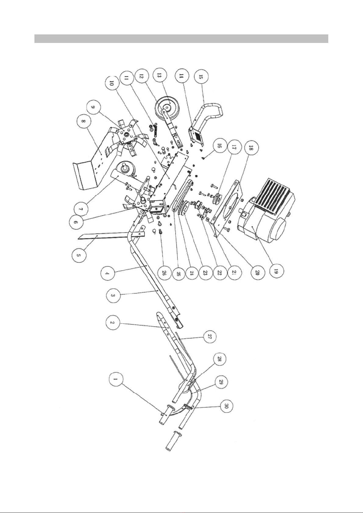
RÄJÄYTYSKUVA JA OSAT ●EXPLODED VIEW AND PARTS

11
Nro Kuvaus Kpl Nro Kuvaus Kpl
1 Kädensijat 2
16 Iskunvaimennin 2
2 Takaohjaintanko 1
17 Hihnapyörä 1
3 Etuohjaintanko (oikea) 1 18 Moottorin istukka 1
4 Etuohjaintanko (vasen) 1 19 Moottori 1
5 Syvyydensäädin 1
20 Vaimennin 1
6 Jyrsinterä (oikea) 1 21 Pyörän istukka 1
7 Hidastin 1
22 Hihnapyörä 1
8 Roiskesuoja 1
23 Hihnapyörä 1
9 Jyrsinterä (vasen) 1 24 Rengas 1
10 Eristekokoonpano 1
25 V-hihna 1
11 Jousi
26 Tappi 1
12 Pyörän kannatinkokoonpano 27 Kaasuvaijeri 1
13 Kumipyörä
28 Kaasuvipu 1
14 Etusuojus 1
29 Kytkinvaijeri 1
15 Nostokahva 1
30 Kahva 1
No Description Q’ty No Description Q’ty
1 Handle bar cover 2 16 Shock absorption mat 2
2 Rear handle bar 1 17 Main V-wheel 1
3 Front handle bar(right) 1 18 Engine seat 1
4 Front handle bar(left) 1 19 Engine 1
5 Adjustable lever 1 20 Cushion 1
6 Tines right 1 21 Tension wheel seat 1
7 Retarder 1
22 Belt wheel 1
8 Mudguard 1
23 Sub V-wheel 1
9 Tines left 1 24 Ring 1
10 Insulation board assembly 1 25 Triangle V-belt 1
11 Spring
26 Pin 1
12 Wheel bracket assembly 27 Throttle wire 1
13 Rubber wheel 28 Throttle switch 1
14 Front guard 1 29 Clutch throttle 1
15 Lift handle 1 30 Handle 1

12
EY-VAATIMUSTENMUKAISUUSVAKUUTUS
Isojoen Konehalli Oy
Keskustie 26, 61850 Kauhajoki As
Suomi
vakuuttaa täten, että
PUUTARHAJYRSIN
malli nro XTP4
on konedirektiivin no. 98/37/EY mukainen.
Tuote täyttää seuraavien standardien vaatimukset:
EN 709:1997+A1:1999
Mikäli tuotteen teknisiä ominaisuuksia tai
käyttöominaisuuksia muutetaan ilman valmistajan
suostumusta, tämä vakuutus
lakkaa olemasta voimassa.
Päiväys: 11.12.2009
Allekirjoitus:
____________________
Harri Altis - Ostopäällikkö
EC-DECLARATION OF CONFORMITY
Isojoen Konehalli Oy
Keskustie 26, 61850 Kauhajoki As
Finland
herewith declares that
TILLER
model no. XTP4
is in conformity with the Machinery Directive no. 98/37/EC.
The product fulfils the requirements of the following standards:
EN 709:1997+A1:1999
This declaration is not anymore valid if the technical features
or other features of the tool are changed without
manufacturer’s permission.
Date: 11.12.2009
Signature:
____________________
Harri Altis - Purchase Manager
Table of contents
Languages:
Other IKH Tiller manuals

Popular Tiller manuals by other brands


KingKutter
KingKutter TG-48-XB Operator's manual

EarthWise
EarthWise TC70065 owner's manual

EarthWise
EarthWise TC70025 Operator's manual

FLORABEST
FLORABEST FGH 710 A1 translation of original operation manual

Troy-Bilt
Troy-Bilt 645A Super Bronco Operator's manual

SNOWJOE
SNOWJOE SUNJOE TJ603E-RM Operator's manual


