Gama Garden GT-35 User manual

Instruction manual
Petrol Powered cultivator
Model: G T- 35

Dear Customer,
Thank you for choosing the „GAMA GARDEN” petrol cultivator.
Prior to starting to use the petrol powered cultivator*, please read this instruction manual carefully and get acquainted with the controls
in order to ensure proper and safe operation.
Purpose
Cultivator application:
- soil cultivating and tiling in gardens (with the safety engineering instructions included in the instruction manual observed and the
technical characteristics taken into consideration). The cultivator is designed for household application.
Main technical characteristics:
Model
GТ- 35
Motor
3HP
Type
Four-stroke, air-cooled, with top valve
arrangement
Working cylinder volume, cubic centimetre
87
Sound power level dB (LwA)
96 dBA
Sound pressure level dB (LpA)
84 dBA. / K=1,5
Vibration value:
2,6 m/s² / K=1,5
Fuel tank volume, litre
1,5
Engine case volume, litre
0,4
Air filter
Made from durable, porous material
Ignition system
Type
Electronic
Starting switch
Floating
Spark-plug
E7RTC
Gap between the electrodes, mm
0,7 –0,8
Controls
Starter
Manual, with automatic return of cord
Air valve control
Rotary
Fuel cock
Operating characteristics
Number of speeds
1, forward
előre
Maximum tilling width, cm
25 / 46
Blade diameter, cm
26
Blades rotary speed, rev./min.
160
Weight of the unit (without packaging), kg
32
For your safety
Use the cultivator properly.
Improper use of the cultivator means failure to observe the
instructions of the manual.
The manufacturer will not assume any responsibility for
injuries resulting from improper use of cultivator. In this case
user will bear all responsibilities.
The manufacturer will not bear any responsibility for faults
which occurred because the user made modifications
arbitrarily in the structure of the cultivator.
(*) –Hereinafter «cultivator».
2
Principal safety engineering rules
Prior to the first use of the cultivator, read the instruction
manual carefully. Other users must also be informed of those
included in the instruction manual.
The instruction manual must be kept during the whole period
of use of the cultivator.
In case of owner change, the instruction manual must be handed
over to the new owner together with the cultivator.

3
Principal safety engineering rules for the work
performance
This chapter describes the principal safety engineering rules
of work performance with the cultivator. The warnings
concerning the users’ safety and structural characteristics of
the cultivator are included in the relevant chapters of the
instruction manual.
Prior to use of cultivator
The cultivator must not be used by persons who are under the
influence of alcohol, drug or medicine.
Persons below 16 years of age must not use the cultivator.
Make sure that all unauthorised persons, including children
and domestic animals, are staying outside the efficient range
of the cultivator.
During work performance with the cultivator
During work performance, wear protective clothing, secure
footgear, goggles and gloves.
Do not refill the cultivator fuel tank while operating. Petrol may
be refilled only outdoors.
Perform the work far away from open flames and sparks and
avoid smoking.
Do not touch the rotary blades of the cultivator by your hand,
foot or even your clothing. The cultivator motor, exhaust
silencer and reducer will warm up during the work
performance and cool down continually.
The engine can be stopped in the following cases:
When the work performance with the cultivator is
finished;
During maintenance and adjustment operations;
When the cultivator is relocated from a working site to
another
Store the cultivator and the petrol in a place unreachable for
children and at a safe distance from sparks, fireand radiators.
Prior to locating the cultivator in a closed room for permanent
storage, wait for the motor to cool down entirely. The parts
must be in compliance with the manufacturer’s specifications.
Use only original parts.
The cultivator may be repaired only by an authorised service
repair shop.
Safety engineering devices
Clutch lever
When the clutch lever is released, the cultivator rotary blades
will stop.
Do not change or block the operation of the clutch lever in any
way.
Guard
It will protect the user from injuries caused by pieces of soil
flying out from under the cultivator rotary blades.
The guard must always be in a condition ready for service.
Handlebar cross-tube
It will ensure the distance between the user and the cultivator
rotary blades.
Information on the cultivator
For ensuring safe operation and maintenance of the
cultivator, each symbol can be seen on the device in the form
of die stamped or projected picture.
Placeof fuel refilling.
Location: on the fuel tank cover.
OHV
Indication of engine of top valve arrangement.
Location: on the cover of the valve mechanism.
ATTENTION: Hot surface!
Location: on the cover of the exhaust silencer.
START
Location: on the handle of the pull cord.
CHOKE
RUN
Air valve handle bar
Positions:
1. CHOKE –fully closed.
2. RUN –fully open.
Location: on the air filter cover.
ON/OFF
Fuel metering valve.
Positions:
1. ON –open. 2. OFF –closed.
Location: on the motor case.
ON/OFF
Starter switch. Positions:
1. ON –switched on. 2. OFF –switched off.
Location: on the motor case.
Stickers showing the operations done by the
controls Control of the rotation of the rotary blades
When the handle of the rotary blade is pressed,
the cultivator rotary blades start to rotate.
Location: on the handle driving the rotary blades.
Warning symbols
There is a sticker containing warning symbols on the
cultivator guard. Prior to starting the operation, get
acquainted with these warnings and apply them during your
work. Prior to starting to use the cultivator, read
the instruction manual, but mainly the
section "For your safety".
Risk of injury by the rotary blades -
Keep your hand and feet away at a safe
distance from the rotary blades.
Risk of injury or risk of damaging the objects
found nearby. Make sure that all
unauthorised persons, including children and
domestic animals are staying out of the
efficiency range of the cultivator.
DO NOT WORK WITHOUT THE GUARD
BEING INSTALLED. Prior to performing the
cultivator maintenance, remove the cap of
the high voltage line from the spark-plug of
the motor.

4
Symbols found in the instruction manual
The following symbols are found in the instruction manual:
Danger
It draws the user’s attention to such sources of danger which
may cause injury to the user during the work performance
with the cultivator.
Warning
It draws the attention to such sources of danger which may
cause damage to the cultivator in case of improper use.
Arrangement of main parts of the cultivator
1 –Handle bar bracket, 2 - Handle, 3 –Clutch lever, 4 –Handle, 5 –Clutch cable
6 –Depth limiter, 7 –Transport wheel, 8- Throttle control, 9 –Throttle cable
10 –Engine, 11 - Deflector, 12 –Tine
Figure: 1.
Assembly
Warning
When unpacking the machine, be especially careful not to
damage the clutch cable.
Assemble the cultivator in accordance with the figures found
in the instruction manual.
1. Setting the plough iron bracket
1. In order to facilitate assembly of cultivator, place a
support of 10-15 cm height under the front section of the
guard (see: Figure 2).
Figure
2
10 –15 cm

5
2. By means of a 13 mm key, screw down and remove the
six М8х12 bolts from the left and right side of the
reducer (see: Figure 3).
М8х12 screw
Figure
3
3. Place the plough iron bracket on the reducer, while
placing the right section of the bracket between the
reducer and the shield lug and the left section between
the reducer and the guard clamp (see: Figure 4, 5).
2. Setting the plough iron in operating
position
Tilling depth is defined by the position of the plough iron as
compared to the bracket. There are wheels mounted on the
plough iron for the transportation of the cultivator.
For performing the tillage, set the plough iron with wheel up.
Setting the blade:
Depth of soil tilling is defined by the plough iron (tilling depth
limiter), which can be found in the lower part of the cultivator,
under the handlebar. There are wheels mounted on the
plough iron for the transportation of the cultivator. For soil
tilling, set the plough iron with wheel up (see: Figure 6).
Shield lug
Plough iron set
properly
Blade
bracket
Figure
4
Figure
6
Pull out the cotter pin (Point 1), remove the retaining pin
(Point 2), then remove the plough iron with wheels (Item
3) from the jointing bracket.
4. Fit the plough iron bracket holes and the reducer holes
(from which bolts have been removed as per Point 2)
together, then screw in the six М8х12 bolts with washer by
hand. Screw the central bolt in the reducer (from the right),
installing it in the hole of the shield lug (see: Figure 4)
.
Guard
clamp Plough
iron
bracket
Figure
5
Note: USE ONLY М8Х12 BOLTS.
Warning!
Do not tighten the six М8х12 bolts when performing Point 4.
4. By means of a 13-mm key, holding the head of the bolts,
screw off the M8 nuts with bolts of 13mm and remove
the М8х90 bolts from the handlebar bracket.
5. Insert the handlebar bracket in the plough iron bracket,
and place the bolts removed as per Point 5 in the
relevant holes of the brackets from outside.
6. Using 13-mm keys, tighten all the bolts installed as per
the previous point, starting with those fastening the
plough iron bracket to the reducer.
Place the plough iron in the bracket in such a way that
wheels stand upwards (Item 4).
Fit the hole of the bracket together with one hole of the
plough iron (Point 5), fasten it with bolt pin (Item 6) and
cotter pin (Item 7).
For increasing tilling depth, increase the length of plough iron
lower part.
Note: For efficient work performance, make sure that
plough iron is set properly as compared to the jointing
bracket (see: addition to Figure 6).
3. Assembly and installation of blades
Install the blades on the blade holder (Figure 7) using
М8х25 bolts, 8 washer and М8 nut (Figure 8). This
component is installed on the left side in the direction of
travel. When installing the component, make sure that
cutting edge of blades are set in accordance with the
cultivator’s direction of travel. If the component is properly
assembled, then the curve of the blade nearer to the reducer
will show from the reducer to the driver.
The right side element must be assembled in the same way,
in opposite-hand view.
Figur
e 7

6
Blades
nearer to
the
reducer
screw off and remove М5х20 bolts from the clamps (see:
Figure 10) from the upper section of the handlebar,
preventing the nuts from falling out.
3. Set the proper part of the cross-tube in the holes of the
clamps, and fasten it with the bolts removed earlier.
Figur
e 8
Note: on the blades of the component,
embossed letters (L), (R) are found, meaning L- left-side
blade, R-right-side blade.
Warning
Figure
11
М8х100 bolts
1. Setting the blades on the reducer
Place the blade holders (assembled with blades) on the
reducer shaft (Figure 9, Item 3) from both sides, fit the
holes of the reducer shaft with holes of blade holders, and
fasten them with bolt pins and cotter pins (Figure 9, Item 1
and Item 2).
Note: set the cutting edges of blades in the direction of
rotation.
31
2
Figure
9
4. Setting the handlebar
The handlebar consists of the following (see: Figure 10):
Right section of handlebar;
Left section of handlebar;
Cross-tube connecting the right and left side
When installing the handlebar, do not turn over or break the
control cable.
5. Adjusting the clutch cable tensioning
With the clutch lever being released (not pressed), pull the
pull starter handle several times. During this, the blades
should not turn over. If they still turn over, loosen the cable
tensioning by means of the regulating sleeve.
1. Loosen the fastening nut (see: Figure 12, Item 2) and
slightly screw the sleeve (Item 1) in the body (Item 3).
2. Strongly tighten the fastening nut to the body of the
regulating sleeve.
3. Check the clutch cable for tensioning.
Figure
12
Note: In the following, in case of the drive-belt’s wearing and
elongating the tension can be set by means of the sleeve
which is found in the clutch lever body (at the beginning, the
sleeve is fully screwed in).
For tightening the clutch cable, screw off the fastening nut
(See: Figure 13) and slightly screw off the cable sleeve.
Figure 10
1. Fit the fastening holes of the left side and right side of the
handlebar together with the holes found in the upper
section of the handlebar holder, then fasten them with
М8х100 bolts and nuts (see: Figure 11).
2. By means of a 4-mm key (not included in the scope of
supply),

7
Figure
13 Figure 14
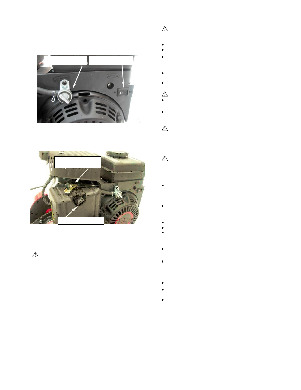
2. Filling up the fuel tank with petrol
Filling-up of fuel tank with petrol is done prior to starting the
engine. Do not open the fuel tank cover if the engine is hot or
operating.
Screw on the fastening nut and check the clutch cable
again for proper tensioning.
Operation
Prior to the first use
Warning
CHECK THE TIGHTNESS OF ALL THREADED
CONNECTIONS ON THE CULTIVATOR, INCLUDING THE
FIXATION OF THE ENGINE.
1. Filling up the engine case with oil
Warning
THE CULTIVATOR ENGINE CASE IS DELIVERED
WITHOUT OIL!
Prior to the first start of the engine, fill up the case with oil of
proper amount that is 0.4 litres.
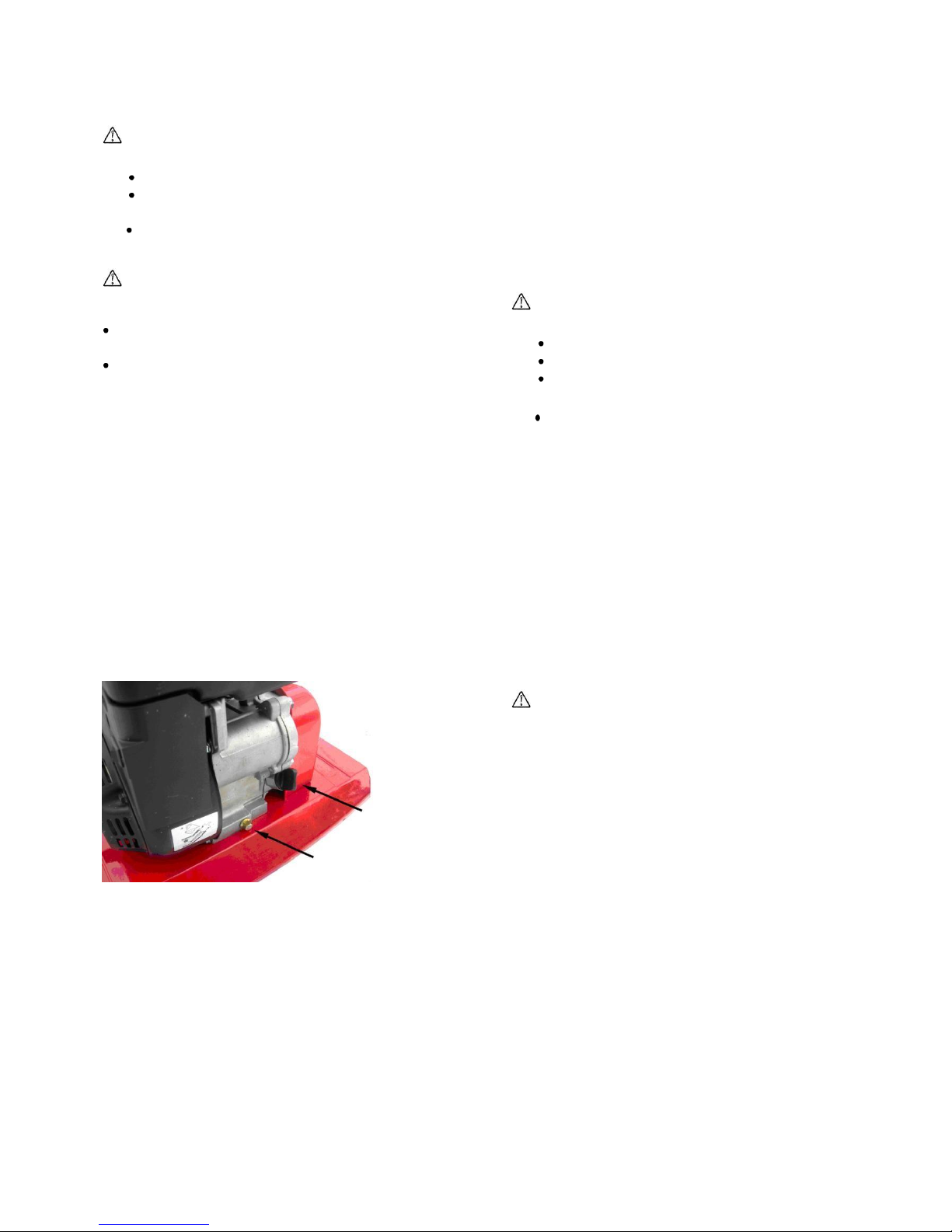
The oil level should reach the lower level in the oil filling
outlet when standing straight (see: Figure 14).
Choose the oil viscosity in accordance with the ambient
temperature, using the diagram below:
The following codes must be found on the oil can: API "SF” or
“SG”, “SH”, “SJ”, “SL”, “SM”.
Under normal operating conditions and in normal temperature
ranges, we recommend the following oil viscosity: SAE 10W-
30.
Note: The oil level check is done with cold engine not
operating. Place the cultivator on a straight, horizontal
surface, supported on the blades and the wheels.
1. Screw off the oil filler cover (see: Figure 14).
2. Check the oil level and fill it up if necessary.
3. Place back and screw in the oil filler cover.
Order of checking the oil level:
Warning
The oil level must reach the lower level in the in the oil filling
outlet.
Prior to filling up with petrol, place the cultivator in a place
where it is not subjected to the action of fire or spark.
Safety engineering rules during operations with
petrol
Danger
Petrol and its vapour may easily flame up and explode!
Prior to filling up, stop the engine and wait until it cools
down entirely.
Wipe through all parts of the cultivator on which petrol
dropped during the filling-up.
Start the engine far away from the place where the filling-
up was made and where the petrol flew out on the earth.
Prior to starting the engine, make sure that the fuel tank is
properly fastened and its cover is screwed tight.
Storethe petrol only in special, clean and closablecans.
Do not let petrol get on your skin and do not inhale its
vapours.
Danger! Petrol must be stored in a place
unreachable for children!
DO NOT SMOKE WHILE FILLING UP THE ENGINE
WITH FUEL.
For the prevention of fire, clean the cultivator components
including the engine surface, the exhaust silencer and
the fuel tank from grass. When filling up with petrol, use
a clean funnel.
The engine should be filled up with clean, fresh, non
ethylated, lead free petrol of octane number at least 95.
Fill up the petrol in such a way that its level does not
exceed 1 cm distance from the upper edge of the mesh
filter.
DO NOT USE CONTAMINATED PETROL OR PETROL
MIXED WITH OIL.
Note: In order to avoid unstable operation of the engine,
always fill up the petrol in due time.
Engine start-up
Danger! Carbon monoxide poisoning will occur if you
inhale the exhaust gases.
DO NOT start the engine in closed premises.
Prior to the engine start-up:
Check whether there is petrol in the fuel tank, and
check the oil level in the engine case.
Make sure whether the clutch lever is pressed on
(whether it is blocked in pressed-on condition).

8
Order of start-up:
1. Set the fuel feed lever to the right “ON” (“turned on”)
position (see: Figure 15).
2. Tightly fit the cap of the high-voltage cable on the spark-
plug.
3. Set the switch in the “ON” position (“Turned on”) (see:
Figure 15).
Figure 15
4. In case of starting cold engine, set the air valve switch of
carburettor in “CHOKE” position (“fully closed”) (see:
Figure 16).
Figure 16
Pull slowlythe pullhandleuntil you feel opposition. After that,pull
out the starter cord in its full length, negotiating the compression.
Let the pull handlebackin the starting position whileholdingit.
Warning!
Failure to comply with this requirement may result in
mechanical damage of the starter.
5. If the engine does not start, repeat those included in Point
4.
6. At low temperatures, warm the engine for 2-5 minutes in
order to avoid unstable operation. When the engine has
warmed through, turn the air valve switch in “RUN”
position (“fully open”).
Engine stop
1. Release the clutch lever.
2. Set the starter switch in “OFF” (“Turned off”) position
(see: Figure 16).
3. Put the feed cock of the fuel feed system in “OFF” position
(“closed”).
Cultivator use
Danger!
Keep unauthorised persons and mainly children and domestic
animals away in a safe distance from the operating cultivator.
Use only a cultivator absolutely free from any defect.
Make sure that the shield is mounted properly and safely.
Check the area where you wish to use the cultivator.
Remove any object which may get underneath the
blades and fly out from under the cultivator.
Use the cultivator only daylight or with proper artificial
lighting.
Do not use the cultivator for tilling such soil where there
can be found great stones, soil heaps, or ditches nearby.
Danger: fire may occur!
Avoid open flame, spark sources and smoking during the
use of the cultivator.
DO NOT USE THE CULTIVATOR WITH CLUTCH LEVEL
NOT FULLY PRESSED IN SINCE IT WILL RESULT IN
THE EARLY WEARING OF THE DRIVE-BELT.
Warning!
During the work performance, avoid blocking of the blades
while the engine is running and the clutch is pressed in
because it may cause damage to the cultivator.
1. Cultivation
Danger: the cultivator or other objects may get
damaged.
1. Start up the engine (see: section “Engine start-up ").
2. Press the clutch lever and hold in pressed position in
order to start the cultivator blades.
DO NOT USE THE CULTIVATOR IN SUCH A PLACE
WHERE GAS CONDUITS, ELECTRICITY SUPPLY
CABLES OR OTHER UNDERGROUND
COMMUNICATION CABLES CAN BE FOUND.
Do not use the cultivator next to trees, since the root of the
trees may become damaged and the cultivator blades
may get blocked.
It is not recommended to work in damp soil.
Great, hard soil pieces may cause failure to the blades.
If foreign objects are caught under the blades (stones,
bars, wires, etc.), then stop the engine and see whether
the cultivator has got damaged.
DO NOT USE THE CULTIVATOR IF IT HAS ANY
OPERATING TROUBLE.
The best result can be achieved with cultivation several
times in higher and higher depths. It will allow the smooth
spreading of the soil previously ploughed. Soil fertility will
improve if plant residues are ploughed in the soil.
Go through the area to be cultivated in straight angle.
Adjust the tilling depth in accordance with the soil
condition. Cultivate the hard soil several times.
For performing cultivation process, adjust smaller tilling
depth.
Starter switch
Fuel cock
Air valve control
Fastening screw

9
2. Work performance on slopes
Danger: Injury may occur as a result of the
cultivator’s turning over.
Apply special care during the change of direction. The
cultivator can be moved transversely on a slope. Do not
move the operating cultivator up and down the slope.
IT IS STRICTLY FORBIDDEN TO USE THE
CULTIVATOR ON A SLOPE EXCEEDING 20%.
Transportation
The cultivator may be transported by any means of transport
which can ensurecultivator integrity.
1. Transportation in short distances
For transporting the cultivator from an area to be cultivated to
another, use the wheels found on the plough iron.
1. Insert the plough iron in the bracket in such a way that
the wheels are down.
Note: Setting the plough iron in transportation position is
done in reverse order. See the section “Setting the plough
iron”.
2. Press the handlebar down in such a way that the blades
do not touch the soil.
3. Relocate the cultivator carefully.
2. Transportation in longer distances
Warning!
Do not carry the cultivator when turned over or turned on its
side. Stand the cultivator on the blades and the wheels.
Risk of injury!
Periodical maintenance:
Stop the engine.
Remove the cap of the high-voltage cable from the
spark plug.
Wait for the engine to cool down entirely.
In case of transportation in a truck or a trailer, fix the
cultivator in order to avoid injuries.
Technical maintenance
For maintaining high level technical characteristics of
cultivator, perform periodical maintenance operation.
Periodical maintenance will help increase engine life and
ensure trouble-free operation.
From the maintenance operations defined in hours or
calendar periods, perform the one which becomes due
earlier. In case of work performance under unfavourable
circumstances, carry out the maintenance more frequently.
Prior to the maintenance of the cultivator:
Risk of injury!
Stop the engine.
Remove the cap of the high-voltage cable from the
spark plug.
Wait for the engine to cool down entirely.
Before each use:
Check the oil level in the engine case. Fill up the oil until
the proper level is reached, if necessary.
Check the threaded connections for safe tightness.
Tighten them if necessary.
After each 5 hours’use:
Check the oil level in the engine case.
Once in each season:
It is recommended to perform service of cultivator in a
specialized service repair shop.
List of operations to be performed
After each
use
Each 25
hour
Each 50
hours
Once in a
season or
each 100
hours
If necessary
Clean the guard and the blades
Clean the air filter (**)
Change the air filter
Change the oil in the engine case (*, **)
Perform lubrication of blade-reducer shaft
Check and clean the spark plug (***)
Change the spark plug
Clean the engine
Adjust the clutch cable
Change the blades
Change the cover of the fuel tank
Change the exhaust silencer
Check the tightness of threaded connections.
Tighten them if necessary.
(*) The first oil change in the engine must be done after two hours following the first work performance.
(**) If the engine works with higher load or under contaminated circumstances, the maintenance should be done more frequently.
(***) The spark plug electrodes must not be scraped or polished with sand.

10
Maintenance operations
Risk of injury in case of accidental start of engine!
Prior to any work done with the cultivator:
Stop the engine.
Remove the cap of the high-voltage cable from the
spark plug.
Wait for the engine to cool down entirely.
1. Cleaning the cultivator
Risk of injury during maintenance of blades!
It is recommended to wear protective gloves during
maintenance of blades.
Clean the guard and the blades after each use, then wash
them with water and wipe them with a cloth.
Clean the engine using a brush and a cloth.
2. Oil change
Note: The oil draining can be made in an engine previously
warmed up.
The first oil change must be done after two hours following
the first work performance.
Order of the oil change:
3. Checking the fuel filter
(If there is any as per the specification)
The fuel filter can be found in the fuel tank where the fuel hose
is connected to it.
Order of checking:
1. Drain the petrol from the fuel tank.
2. Take off the fuel tank and remove the contamination and
the water from it.
3. Check the condition of the fuel filter, and clean or replace
it if necessary.
4. Removing and mounting the blades
Risk of injury during the maintenance of blades!
Prior to any work done with the blades:
Stop the engine.
Wait until the blades stop.
Remove the cap of the high voltage cable from the
spark plug.
Wait for the engine to cool down entirely.
Order of change of blades:
1. Remove the pins, and take out the fastening elements
whichfix the blades to the driving shaft.
2. Remove the blades from the driving shaft.
3. Install the new blades in reverse order.
1.
2.
Screw off the oil filler cover.
(See: Figure 17).
Screw off the cover of the oil drain and let out the used oil.
Note: The cutting edges of the blades should be directed in
the direction of rotation
5. Maintenance of the reducer
.The lubricating oil need not be changed during the whole life
of the cultivator.
6. Maintenance of the engine
3.
Replace the oil drain cover and screw it thoroughly.
4.
Fill oil in the engine in the necessary amount and check
the oil level.
5.
Replace and screw up the oil filler cover.
After each use, clean the engine from dirt using a brush and a
cloth.
Figure 17
Oil filler cover
Oil drain plug
Warning!
In case of repair, use only original parts supplied by the
manufacturer.
Use of non original parts may result in serious damage of the
engine.
7. Checking the spark plugs
For the normal operation of the spark plugs, ensure the
necessary free distance between the electrodes and in
addition clean the spark plug from residue of combustion.
The free distance between the electrodes is 0.7-0.8 mm.
Order of checking:
Note: The oil change must be done more frequently if the
engine is subject to greater load or higher temperature.
Note: The used oil must be recycled. It is recommended to
drain the oil in a can and send it to a processing plant for
regenerating.
DO NOT DISPOSE THE CAN CONTAINING USED OIL AND
DO NOT POUR THE OIL ON THE EARTH.
1. Remove the cap of the high voltage cable from the spark plug
and screw out the spark plug by means of a spark plug key.
2. Inspect the spark plug visually.
3. Clean the spark plug with a brush, if you wish to use it in the
future.
4. Measure the free distance between the electrodes by means of
a special sound (it should be purchased separately). Adjust the
free distance if necessary, by gently bending the side electrode.
5. Check the skirt and threaded part of the plug.
6. Change the spark plug if it seems to be worn out or there is any
crack on the insulator.
7. Replace the plug by hand force, then tighten it with plug key.

11
Warning!
TIGHTEN THE SPARK PLUG THOROUGHLY!
In case of failing to comply with this requirement, the spark
plug will strongly warm up during operation and it will result
in failure of the engine.
8. Maintenance of the air filter
Warning!
DO NOT START THE ENGINE WITHOUT THE AIR FILTER
IN PLACE!
Storage
Danger!
Do not store the engine with petrol in the fuel tank in a closed
room without ventilation, or in the vicinity of open flame and
radiators.
Flashing of the petrol vapour may result in fire which involves
danger!
If you wish to withdraw the cultivator from use for a longer
period, the following actions are to be taken:
Order of checking:
1.
Drain the petrol from the fuel tank in a can.
2.
Drain the oil from the engine case (see the section: “Oil
change in the engine case”).
1.
Screw down the bolts fastening the air filter cover (see: Figure
16).
Remove the air filter cover.
2.
3.
Remove dirt from surface of engine and cultivator then
wipe it dry with a cloth.
3.
Remove the air filter (hereinafter: filter) (see: Figure 18).
4.
By means of a cloth, apply thin layer of machine oil on all
external metal surfaces.
4.
Take out the plastic frame.
5.
Screw off the spark plug. Pour 10 gram of clean oil in the
spark plug opening.
5.
Check the filter for the level of contamination and possible
foreign objects. Inspect it carefully for integrity, existence of
holes and other injuries. Replace it if necessary.
6.
Cover the plug hole opening with a cloth.
7.
Rotate the main shaft of the engine slowly by means of
the starter cable handle.
Warning!
It is strictly forbidden to use petrol or low temperature solvent
for cleaning the filter. It may result in fire or explosion.
Figure
18
6. Wash the filter through in warm soap solution and dry it.
Soak it in one spoon (~ 10 ml) of clean engine oil. Twist
it in order for the oil to spread more evenly on the surface
of the filter and there is no surplus.
7. Place the plastic frame in the air filter case.
8. Replace the filter and the air filter cover in reverse order
then tighten the fastening screws strongly.
Note: Avoid any oil splash from the plug opening while
rotating the main shaft.
8. Replace the spark plug. Do not connect the cap of the
high-voltage cable.
9. Cover the cultivator and place it on a plane surface in a
clean, dry room.
10. The cultivator may only be stored horizontally, supported
on the blades and thewheels.
Warning!
Do not transport a cultivator filled up with oil in a non
horizontal position! In case of failing to keep to this
requirement, the oil will get in the inlet (outlet) connection
which will make it difficult to start the engine and result in high
smoky exhaust.

Possible operating failures and method of repair
In case of any possible failure, use the information found in the table for repair.
Failure
Cause
Method of repair
The engine cannot
be started.
There is no petrol in the fuel tank.
Fill the fuel tank up with clean fresh, lead-free petrol.
The petrol is old.
Drain the old petrol from the fuel tank and fill it with clean
fresh, lead-free petrol.
The engine is cold. The control of the
carburettor air valve is in “RUN” (“Fully
open”) position.
Put the air valve control in “CHOKE” (“Fully closed”)
position.
The fuel cock lever is in “OFF”position.
Put the fuel cock lever in the “ON” position.
The cap of the high-voltage cable is not
attached on the spark plug.
Attach the cap of the high-voltage cable on the spark plug.
The spark plug has become contaminated or
failed.
Clean and if necessary replace the spark plug. Check the
free distance between the electrodes.
The engine does
not smoothly
operate.
The air valve control is set in the wrong
position.
Set the air valve control in the “RUN” (”Fully open”)
position.
There is an improper contact between the
spark plug and cap of the high-voltage cable.
Attach thoroughly the cap of the high-voltage cable onto
the spark plug.
Old petrol. There is water and dirt in the fuel
system.
Drain the old petrol from the fuel tank and fill it up with
clean, fresh, lead-free petrol.
Contaminated air filter.
Clean or replace the air filter.
Blades do not
rotate
Blades are blocked by stones or larger soil
pieces.
Stop the engine and remove cap of the high-voltage cable
from the spark plug. Clean the blades.
The clutch cable is wrongly adjusted.
Adjust the clutch cable. See the section: «Adjustment of
clutch cable».
High level of
vibration
Fixation of blades has loosened or blades
have got damaged.
Stop the engine immediately and remove the cap of the
high-voltage cable from the spark plug. Replace failed
components.
Fixing screws have come loose.
Stop the engine immediately and remove the cap of the
high-voltage cable from the spark plug. Tighten or replace
the bolts.
ATTENTION: For the clearing of faults not treated above, contact the authorised service repair shop.
The manufacturer reserves the right to modify the cultivator structure without previous notification for the improvement of
consumer characteristics.

Terms of guarantee
Please keep carefully the letter of guarantee completed by the seller, or the certificate of purchase. The GAMA
GARDEN will provide 12 months’guarantee from the date of purchase. This guarantee is in compliance with the
technological condition and the purpose of use / field of application. The following guarantee instructions will not
influence customer’s statutory rights.
Preconditions of the 12 months’guarantee:
- The device is used exclusively for private purposes.
The guarantee period will be reduced to half if the machine is used in the commercial sector and in the field of
leasing business.
- Our guarantee is provided under the condition that the machine is handled properly and the instructions given in the
instruction manual are observed.
- The maintenance intervals determined are observed.
- It is forbidden to change the design without permission.
- Original GAMA GARDEN replacement parts / accessories are to be installed.
- The completed letter of guarantee and/or certificate of purchase are to be presented.
This guarantee will not cover normal wear of blades, blade holding components, friction disks, rotating
wheels/tyres, air filters, spark plugs, spark plug connectors and other wearing part. In case of performing any
repair without permission, the whole guarantee will lose effect. Any damage occurred during transportation
must be reported to the carrier instead of us, otherwise all claims for compensation towards the carrier will lose
effect.
This symbol found on the device or the packaging means that the product should not be put in the
household waste. Please take your waste to the disposal site assigned for electrical and electronic devices. Through
the proper handling of devices you will protect the environment and human health from damage caused by
improper handling of waste. Recycling of materials will help preserve the natural resources. For further
information on waste management, contact the competent authorities, the local waste disposal company or the
shop where you purchased the product.
Information on the packaging
The used packaging must be placed in the proper waste collection container.
GAMA Garden Kft., 4900 Fehérgyarmat, Szatmári Street, 11, declares that the device has CE marking (that is the
device meets the requirements of the relevant international standards), and that it is in compliance with the data
included in the Instruction manual and the data table. This statement is based on TÜV certification.
Table of contents
Other Gama Garden Tiller manuals