iKonavs DRS User manual
Ikon AVS ltd DRS V1.00
1
DRS
Description
An integral part of the IKON AVS fault monitoring network, the DRS will monitor
up to twenty four external sensor inputs and report these locally as well as via a
dual fibre network.

Ikon AVS ltd DRS V1.00
2
Contents
DESCRIPTION 1
CONTENTS 2
DRS INTRODUCTION 3
FUNCTIONALITY 4
REAR PANEL CONNECTIONS 6
Group Inputs 6
FUSE 6
Common Fault 6
Power Supply 7
Fibre Connectors 7
APPENDIX A 8
UNIT AND INPUT DIAGNOSTICS 8
RAW DATA 9
TEST Mode 9
APPENDIX B11
RS232 CONNECTING DETAILS 11
APPENDIX C12
INPUT DESCRIPTION 12
Connections 12
Configuration 14
SID/ JNR DRS SETTINGS 15
Setting selector 15
Event input settings 15
APPENDIX D16
COMMON FAULT RELAY 16
APPENDIX E17
POWER SUPPLY 17
DC POWER INLET 17
APPENDIX F18
OPTICAL FIBRE CONNECTORS 18
MANUFACTURERS INFORMATION 19

Ikon AVS ltd DRS V1.00
3
DRS Introduction
The DRS can monitor up to twenty four separate external circuits and features:-
ۥ Twenty-four inputs in six groups of four.
€‚ Inputs suitable for 12V, 24V, Open Collector and Volt Free
operation.
€ƒ Mains and DC operation.
€„ Common fault output.
Front panel indicators confirm the current status of the connected inputs whilst the
comprehensive diagnostics ease external input and DRS testing.
It is used in conjunction with SID or JNR as part of an IEC 60849 compliant system to
monitor:-
€… Status of external UPS.
۠ DSP watchdog outputs.
€‡ External relay & alarm circuits.
€ˆ Third party, non-networked VA equipment.
A windows based software utility is available for use with the unit allowing simple
system configuration and adjustments. The software allows unit identification,
selection of monitoring type, configuration of the inputs and common fault output
as well as monitoring of mains & DC supplies.

Ikon AVS ltd DRS V1.00
4
Functionality
Front Panel Controls [See Appendix A]
Front panel controls allow configuration of the unit and LED’s display the current
status of each individual circuit.
The Rx and Tx leds flash to confirm fibre communications.
The PRI and SEC leds indicate a fibre fault
The OK led flashes when any new fault is detected on the
inputs, the units power sources or fibres and the common
fault relay is de-energised.
Press the OK button and the led will illuminate continuously
and the common fault relay is energised. I.e. OK= local fault
acknowledge. When all faults are cleared the led goes out.
The 9 pin D socket is for configuring the unit using the
supplied software. Refer to Appendix B for connection and
software details.
The Diagnostics section is used to
test the units operation as well as
derive additional information on the
connected inputs.
Refer to appendix A for full details.

Ikon AVS ltd DRS V1.00
5
Inputs indicators are split into six groups, each representing a single input socket
on the rear panel. The group name box is sized to allow the use of standard
adhesive labels for ease of user identification.
During normal operation the input leds will be off when no fault is present. They
will flash when a new fault occurs on the input with this changing to a steady ON
state if the local OK button is pressed. When flashing the Common Fault relay is
de-energised.
Ikon AVS ltd DRS V1.00
6
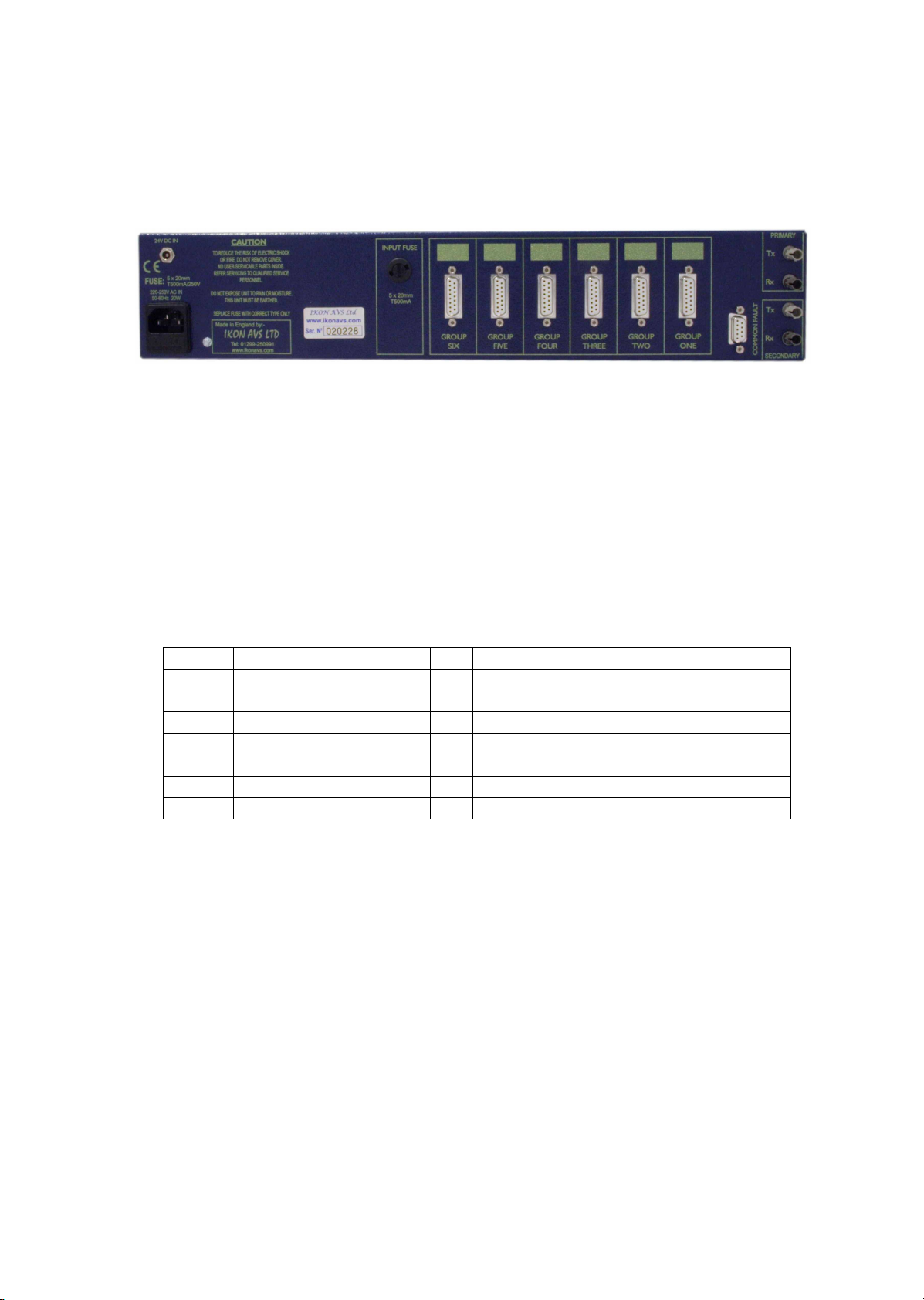
Rear Panel Connections
POWER FUSE GROUP INPUTS COMMON FIBRE
FAULT
Group Inputs
[See Appendix C]
Six sets of four inputs for the connection of external devices. Refer to Appendix C
for full connecting and application details. Each input channel can be configured
for an external input of 12V DC or 24V DC or can use the internal 12V DC power
supply to allow external volt free or Open Collector connections to ground to be
used.
Each group of four inputs is provided with a 15-Pin female Dee-type connector.
Pin 1Input 1, +12V Pin 9Input 1, +24V
Pin 2Input 2, +12V Pin 10 Input 2, +24V
Pin 3Input 3, +12V Pin 11 Input 3, +24V
Pin 4Input 4, +12V Pin 12 Input 4, +24V
Pin 5Input 1, -V Pin 13 +12V out, 100mA max
Pin 6Input 2, -V Pin 14
Pin 7Input 3, -V Pin 15 0V ( common )
Pin 8Input 4, -V
FUSE
Provided for the protection of the internal power supply when using the 12V DC
outputs. Replace fuse with correct type only ( 5 x 20mm T500mA ).
Common Fault
[See Appendix D]
A change over relay provides a common fault output that can be configured to
provide a change in status for any fault.

Ikon AVS ltd DRS V1.00
7
Power Supply
[See Appendix E]
A 230V 50Hz mains supply socket. The mains fuse (T500mA 20mm) is mounted
within this socket. The fuse carrier also contains aspare fuse.
A 24V DC battery backup input is also provided. The software utility allows
status monitoring of both power supplies.
Fibre Connectors
[See Appendix F]
Twin (primary & secondary) ST fibre connectors for incoming and outgoing fibre
connections to other hardware in the system. The software utility allows either
single or dual fibre operation with states of system verified and reported.

Ikon AVS ltd DRS V1.00
8
Appendix A
Unit and Input Diagnostics
The front panel Diagnostics section allows the verification of the units and any
connected inputs status.
The INPUT switch cycles through display modes;-
NORM =Normal The unit is in normal operating mode.
PWR =Power This displays the mains and battery input status on the
adjacent test leds. T2 indicates that the mains input is
OK and T3 that the battery input is OK.
RAW =Raw Data Allows the selection of one of three test modes
selected by the TEST button that cycles the mode
between T1, T2 and T3 as indicated by the leds above
the Test button. See below for further explanation.
TEST This display mode can only be entered into by the
simultaneous pressing of both the TEST and the
INPUTS button whilst in the RAW mode. See below for
additional information.

Ikon AVS ltd DRS V1.00
9
RAW DATA
The individual channel status leds are software derived and can therefore be
configured by the configuration utility to be either on or off when a fault condition
exists.
Often to save power and enable rapid location of a fault the system is configured
to only illuminate a led if the channel is in a fault state, this is totally independent
of the network reporting of the fault. In some cases the system specification
requires the opposite with indicators always on when OK and off when a fault.
Whist both are accommodated within the DRS software it is often useful to be
able to view the actual state of inputs both to assist initial set-up and subsequent
fault finding.
Press the INPUTS button to cycle to RAW.
Now press the TEST button to cycle through the three test modes.
MODE LED FUNCTION
1T1 Each channel led shows the real (raw) state of the
input. If the opto isolator is ON (volts present or
contact grounded) the channel led is ON.
2T2 Shows which inputs are active, i.e. set-up for use
using the configuration utility. If the led is on, its in use.
3T3 Rescans the inputs and shows all current input faults.
TEST Mode
To get to test mode select RAW mode using the INPUTS button and then press
and hold TEST switch. Whilst pressing also press the INPUTS switch, then
release both switches.
Pressing the INPUTS switch without the test switch will cause the DRS to skip
the test mode and go back to normal mode.
Once in test mode all fault monitoring is disabled and the common fault relay is
on. All network reported faults are cleared.

Ikon AVS ltd DRS V1.00
10
There are 12 test mode cycled through with the TEST switch. Mode is indicated
in binary on the T leds. Tests are:-
TEST LEDS
1T1 All groups leds OFF.
2T2 All group leds ON. TEST and all other leds
flashing.
3T1,+T2 Common Fault relay ON. (No faults state)
4T3 Common Fault relay FF. (Fault state)
5T1+T3 Send ‘Mains fail’ message down network.
6T2+T3 Send ‘Battery fail’ message down network.
7T1+T2+T3 Report inputs 1+2+3+4 in fault condition down
network. Group One leds flashing.
8T4 Report inputs 5+6+7+8 in fault condition down
network. Group Two leds flashing.
9T1+T4 Report inputs 9+10+11+12 in fault condition down
network. Group Three leds flashing.
10 T2+T4 Report inputs 13+14+15+16 in fault condition down
network. Group Four leds flashing.
11 T1+T2+T4 Report inputs 17+18+19+20 in fault condition down
network. Group Five leds flashing.
12 T3+T4 Report inputs 21=22+23+24 in fault condition down
network. Group Six leds flashing.

Ikon AVS ltd DRS V1.00
11
Appendix B
RS232 Connecting Details
This is located on the front panel and provides a bi-directional RS232 port used
to communicate with an IBM compatible PC or Laptop.
Please note that the configuration software available is only PC compatible.
Pin 1 No connection
Pin 2 Serial data receive (RX)
Pin 3 Serial data transmit (TX)
Pin 4 No connection
Pin 5 Ground
Pin 6 No connection
Pin 7 No connection
Pin 8 No connection
Pin 9 No connection
Ikon AVS ltd DRS V1.00
12
Appendix C
Input Description
The DRS has six sets of four opto-isolated inputs for monitoring external events.
When the DRS is networked to either a SID or JNR the events can be registered
on an LCD display. All logged faults can then be printed or stored to a log file on
a PC.
Each input channel can be configured for an external input of 12V DC or 24V DC
or can use the internal 12V DC power supply to allow external volt free or Open
Collector connections to ground to be used.
Connectors
Each group of four inputs is provided with a 15-Pin female Dee-type connector.
Pin 1Input 1, +12V Pin 9Input 1, +24V
Pin 2Input 2, +12V Pin 10 Input 2, +24V
Pin 3Input 3, +12V Pin 11 Input 3, +24V
Pin 4Input 4, +12V Pin 12 Input 4, +24V
Pin 5Input 1, -V Pin 13 +12V out, 100mA max
Pin 6Input 2, -V Pin 14
Pin 7Input 3, -V Pin 15 0V ( common )
Pin 8Input 4, -V
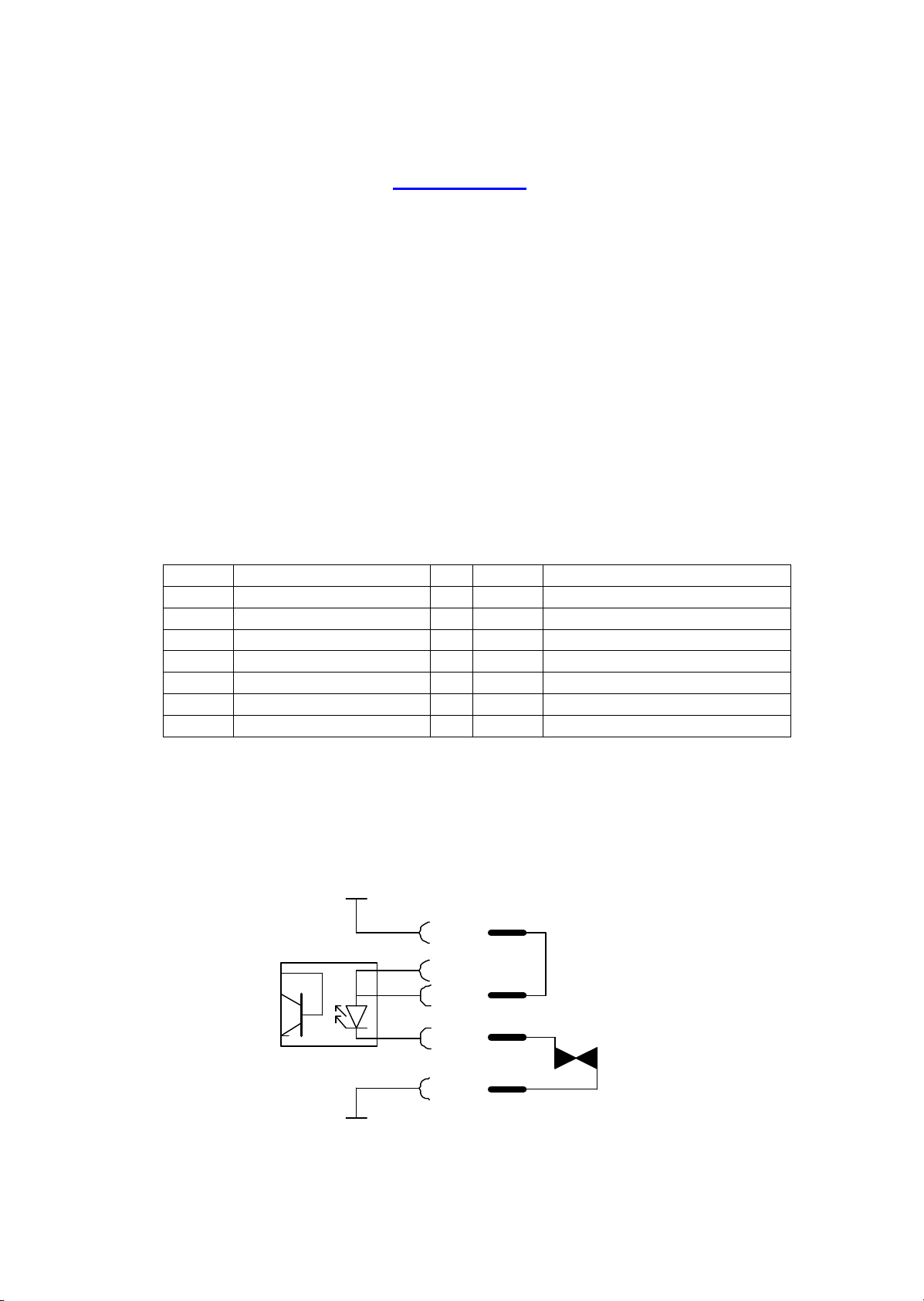
Connections
The diagrams below show how a voltage free or open collector contact should be
wired using the internal 12V power supply.
+12V
In +12
In-
Gnd
Contact
being
monitored
In+24
Ikon AVS ltd DRS V1.00
13
Alternative version using an external open collector rather than a volt free
contact.
+12V
Gnd
Open
collector
being
monitored
In +12
In-
In+24
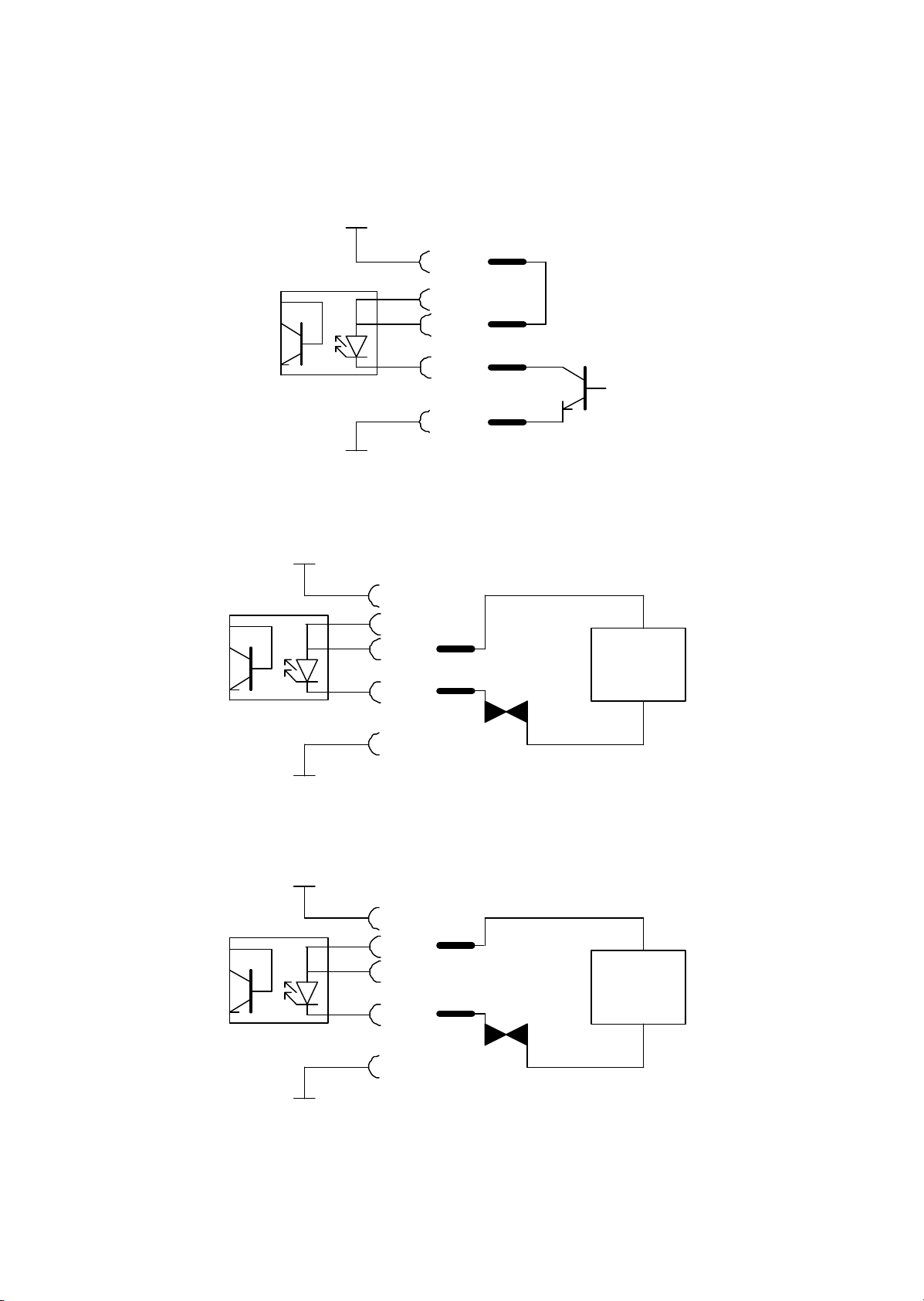
Using an external 12V DC power supply.
+12V
Gnd
Contact
being
monitored
12VD.C.
power
supply
In +12
In-
In +24
Using an external 24V DC power supply.
+12V
Gnd
Contact
being
monitored
24VD.C.
power
supply
In +12
In-
In +24
Ikon AVS ltd DRS V1.00
14
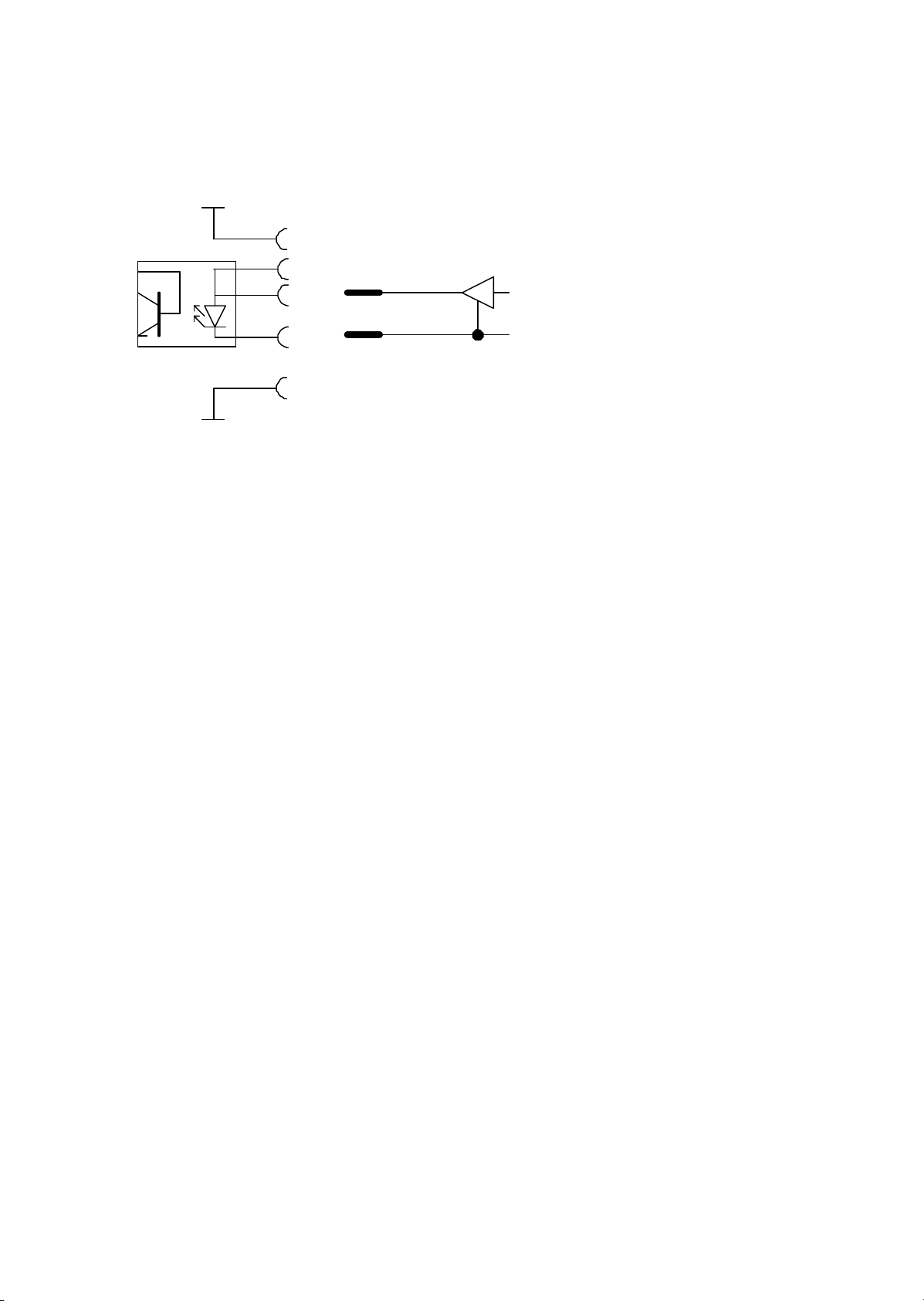
The Opto-diodes can be driven by active outputs as shown below
+12V
Gnd
Opto off =0v @0mA
Opto on =12V @15mA
In +12
In -
In +24
N.B. If an external supply or active drive is used, careful attention must be taken
over ground routing.
Configuration
Each input can be configured to operate in three modes :-
‰Disabled.
‰Fault when opto off.
Fault reported when opto-coupler diode is un-powered and
input OK when powered. This is the recommended mode of
operation as a break in the wiring between the contact and
the input will be reported as a fault.
‰Fault when opto on.
Inverse of above.
The status of these inputs is not latched, each input can be assigned an
individual name for easy fault recognition.
Configuration is carried out using the SID/JNR Utility available from Ikon AVS
Ltd.
Ikon AVS ltd DRS V1.00
15
SID/ JNR DRS Settings
When running the utility and having added a DRS to the configuration, it can set
up as follows.
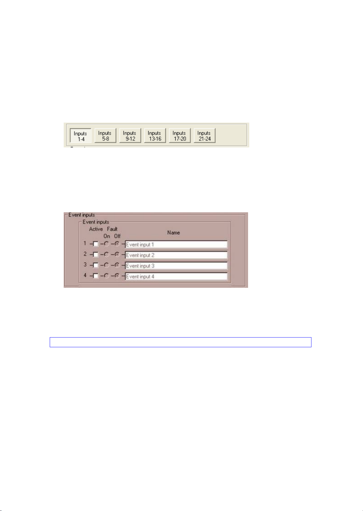
Setting selector
Selects which section of the DRS configuration is displayed and available for
editing.
Event input settings
Displays the operating mode and details of each event input. These are
€Š Name. This is name that SID/JNR will display for this event input in any
event reporting.
Advise. Keep to 16 characters max for JNR and 20 characters for SID.
€‹ Active. When checked the event input will be used by the fault
monitoring system. When unchecked the input is excluded from the
fault reporting.
€Œ Fault On/Off. When On is selected the system will report a fault when
then event input opto is powered. When Off is selected the fault
condition is reported when the event opto is unpowered.

Ikon AVS ltd DRS V1.00
16
Appendix D
Common Fault Relay
The common fault relay is activated on detection of any fault. It could be used to
enable a sounder or light an indicator on detection of a fault, to alert an engineer
of a fault on the system.
Pin 1 Relay Wiper
Pin 2 NC when not in fault
Pin 3 NO when not in fault
Pin 4-9 No connection
The contacts are rated @ 30V 1A

Ikon AVS ltd DRS V1.00
17
Appendix E
Power Supply
230V 50Hz, the mains fuse (T500mA 20mm ) is mounted within this connector.
The fuse carrier also contains a spare fuse. To reduce the risk of fire replace the
mains fuse only with the same type.
DC power inlet
In the case of a mains supply failure the supply (24V+/-1V @1A) provided via this
connector will be used instead. The plug is a standard D.C. connector with
2.5mm internal diameter, 5.5mm external and 14mm long. The central pin is the
positive connection. The status of the D.C. input can be included in the fault
monitoring.
18-30V DC
Ikon AVS ltd DRS V1.00
18
Appendix F
Optical Fibre Connectors
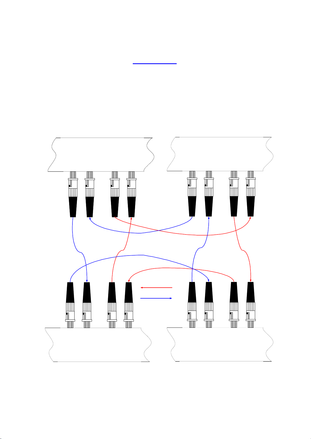
These are ST bayonet connectors operating at a wavelength of 820nm. The fibre
length between units should not exceed 2km (with 2 couplers in line, i.e. for patch
panels). To achieve the required fault tolerance twin fibres loops are used, these
should be routed in physically divergent routes and opposite directions, as shown
below.
Rx
PRIMARY
SECONDARY
Tx TxRx
SECONDARY LOOP
PRIMARY LOOP
Rx
PRIMARY
SECONDARY
Tx TxRx
Rx
PRIMARY
SECONDARY
Tx TxRx Rx
PRIMARY
SECONDARY
Tx TxRx

Ikon AVS ltd DRS V1.00
19
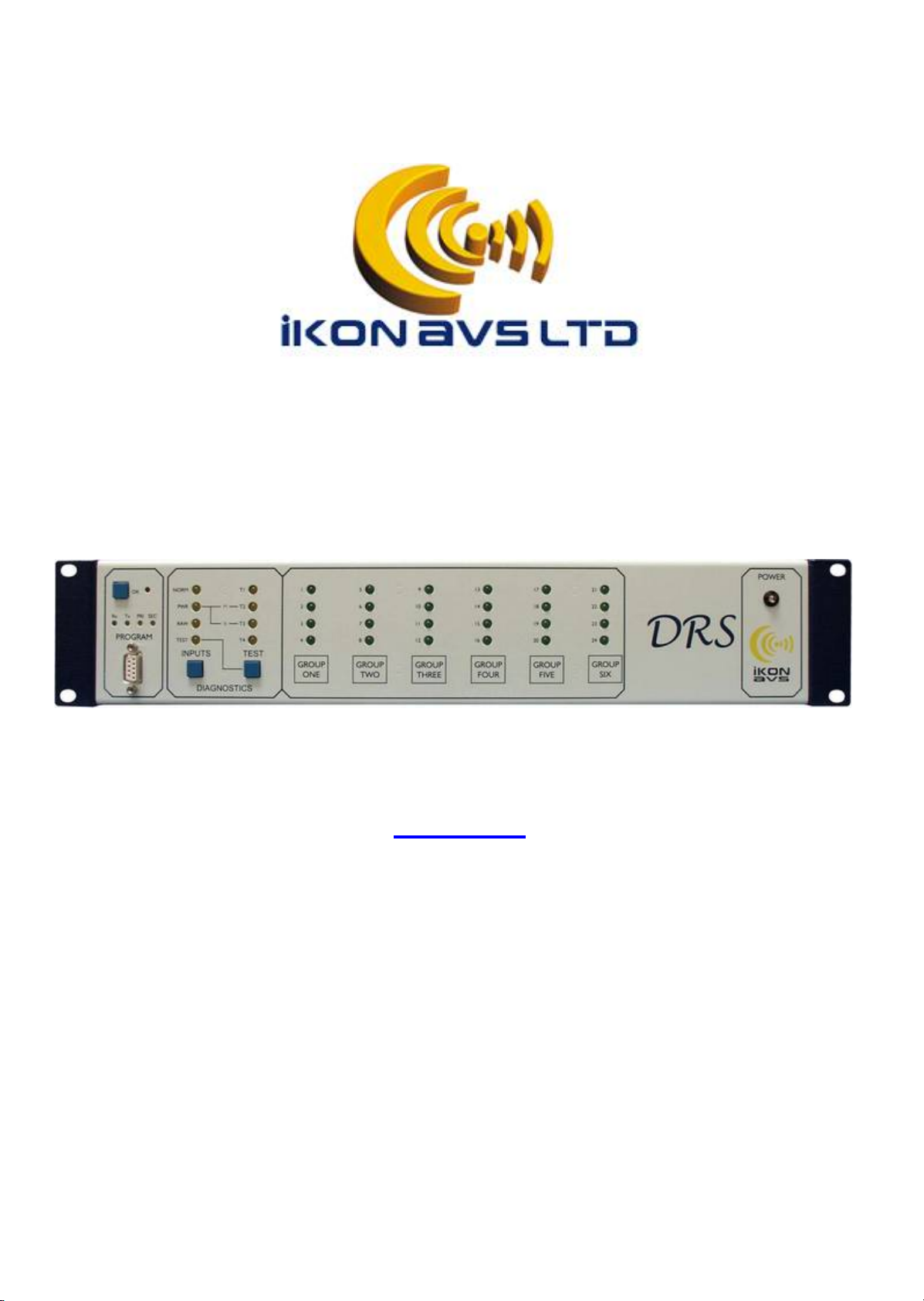
Manufacturers Information
The DRS is manufactured in England by IKON AVS Ltd.
For service or warranty advice please initially contact your supplier. Alternatively
contact the manufactures at:-
IKON AVS Ltd
Unit 238 Ikon Trading Estate
Droitwich Road
Hartlebury
Worcestershire
DY10 4EU
Telephone: (44) 01299 250991
Fax: (44) 01299 250983
Website www.ikonavs.com
Technical support e-mail:-[email protected]
Electromagnetic Compatibility
This equipment has been designed, manufactured and tested to conform to the
European EMC directives EN55103-1 & EN55103-2 for classifications E2 and
E4.
Limitations as to use: 1. The specified equipment is to be mounted into
an earthed, steel equipment rack and not
mounted adjacent to RF transmitting or
receiving equipment.
Table of contents


