TPS WP-84 User manual

Congratulations !
You have purchased the latest in Handheld Conductivity-Salinity-Temperature
instrumentation. We trust that your new WP-84 will give you many years of
reliable service.
The WP-84 is a breeze to operate. This manual has been designed to help you
get started, and also contains some handy application tips. If at any stage you
require assistance, please contact either your local TPS representative or the
TPS factory in Brisbane.
The manual is divided into the following sections:
1. Table of Contents
Each major section of the handbook is clearly listed. Sub-sections have also
been included to enable you to find the information you need at a glance.
2. Introduction
The introduction has a diagram and explanation of the display and controls of
the WP-84. It also contains a full listing of all of the items that you should
have received with your WP-84. Please take the time to read this section, as
it explains some of items that are mentioned in subsequent sections.
3. Main Section
The main section of the handbook provides complete details of the WP-84,
including operating modes, calibration, troubleshooting, specifications, and
warranty terms.
4. Appendices
Appendices containing background information and application notes are
provided at the back of this manual.
TPS Pty Ltd
4 Jamberoo Street
Springwood, Brisbane,
Australia, 4127
Phone :(07) 32 900 400
International :61 7 32 900 400
Fax :(07) 3808 4871
International :61 7 3808 4871
E-mail :[email protected]
Web :www.tps.com.au
Model WP-84
Conductivity-Salinity-
Temp. Meter
Handbook Version : 2.0
Date : 05 Mar 01
Author : MS

Page 2Contents
1. Introduction.....................................................................................4
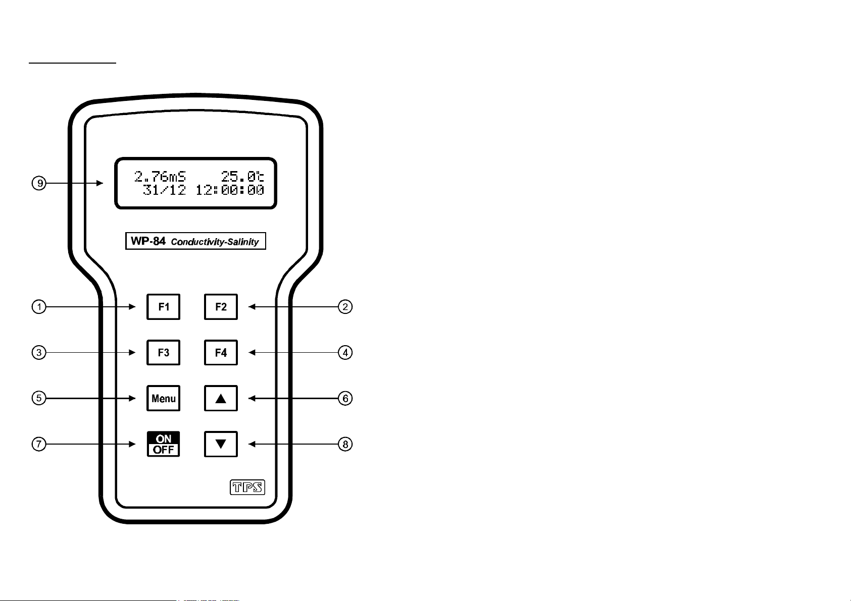
1.1 WP-84 Display and Controls.............................................................................4
1.2 Unpacking Information.....................................................................................6
1.3 Specifications....................................................................................................7
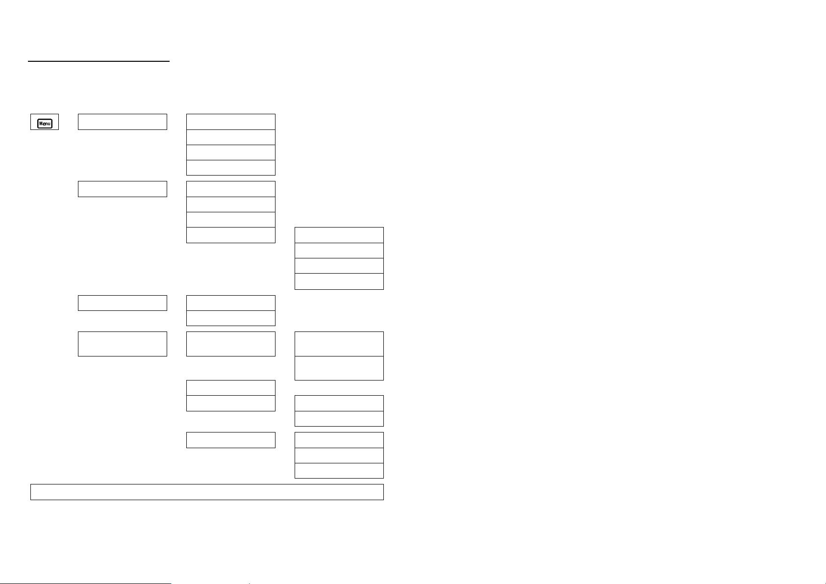
2. WP-84 Menu Structure ...................................................................9
3. Conductivity Mode........................................................................10
3.1 Selecting Conductivity Mode ..........................................................................10
3.2 Conductivity Calibration.................................................................................11
3.3 Calibration Notes............................................................................................12
3.4 Calibration Messages......................................................................................12
4. Salinity Mode................................................................................. 13
4.1 Selecting Salinity Mode ..................................................................................13
4.2 Conductivity Calibration.................................................................................14
4.3 Calibration Notes............................................................................................15
4.4 Calibration Messages......................................................................................15
5. Temperature Calibration ..............................................................16
5.1 Calibration Procedure .....................................................................................16
5.2 Calibration Notes............................................................................................16
5.3 Calibration Messages......................................................................................16
6. ATC Coefficient.............................................................................18
6.1 Setting the ATC Coefficient............................................................................18
6.2 Calculating the ATC Coefficient of a Solution ................................................19
7. Good Laboratory Practices (GLP)...............................................20
7.1 To recall GLP information on the display........................................................20
7.2 Failed Calibration...........................................................................................21
7.3 Printing GLP Information to the RS232 Port...................................................22
7.4 Instrument Serial Number...............................................................................22
7.5 Additional GLP Features.................................................................................22
8. Notepad Function.........................................................................23
8.1 Recording Readings into the Notepad..............................................................23
8.2 Recalling Records from the Notepad ...............................................................23
8.3 Erasing Records from the Notepad..................................................................23
8.4 Printing Records from the Notepad to the RS232 Port.....................................24
9. Automatic Datalogging.................................................................25

Page 3
10. RS232 Port................................................................................. 27
10.1 Setting the Baud Rate .................................................................................27
10.2 Sending Readings to the RS232 Port...........................................................27
10.3 RS232 Configuration..................................................................................27
10.4 Communication and Statistical Software.....................................................27
10.5 Commands..................................................................................................28
10.6 Data Format................................................................................................29
10.7 GLP Data Format........................................................................................30
11. Battery Saver Function.............................................................31
12. Clock Function.......................................................................... 32
12.1 Setting the Clock ........................................................................................32
12.2 Displaying or Hiding the Clock...................................................................32
13. Selecting k=0.1 or k=10 Sensors ............................................. 33
14. Initialising the WP-84 ................................................................34
15. Instrument firmware version number.......................................34
16. Troubleshooting........................................................................35
16.1 General Errors............................................................................................35
16.2 Conductivity and Salinity Troubleshooting..................................................36
16.3 Temperature Troubleshooting.....................................................................38
17. Warranty ....................................................................................39
18. Appendices................................................................................ 41
18.1 Care, Cleaning and Maintenance of Conductivity Sensors...........................41
18.2 Replatinising Conductivity Sensors.............................................................42

Page 4
1. Introduction
1.1 WP-84 Display and Controls

Page 5
¬
Press to record readings into memory. See section 8.1.
-
Press to show or hide the date and time. See section 12.2.
Also used to select k=0.1 or k=10 sensor, when the standard k=1 sensor is not
being used.
®
Press to start or stop automatic logging. See section 9.
Alternatively, press to transmit current reading plus date and time to the RS232
port (optional). See section 10.2.
¯
Only used within the menu system on the WP-84.
°
Press to access the user-friendly menu system which makes the WP-84 a breeze to
operate.
±and ³
The and keys are used when calibrating temperature readout (section 5),
setting the clock (section 12.1), setting the automatic logging period (section 9),
and displaying GLP information (section 7.1).
The key is also used to initialise the WP-84 at turn-on. See section 14.
²
Switches the WP-84 on and off.
´Display
32 character alpha-numeric display with user-friendly menu and prompting
system. Shows Conductivity/Salinity and Temperature simultaneously. Date and
time can also be displayed.

Page 6
1.2 Unpacking Information
Before using your new WP-84, please check that the following accessories have
been included…
Part No
1. WP-84 Conductivity-Salinity-Temperature Instrument..........................122159
2. k=1/ATC/Temperature Sensor, Plastic body, 1m cable .........................122201
3. 2.76mS/cm Conductivity Standard, 200mL...........................................122306
4. 2 ppK Salinity Standard, 200mL ..........................................................122307
5. Battery charger.....................................................................................130037
6. WP-84 Handbook ................................................................................130050
Options that may have been ordered with your WP-84…
1. k=10/ATC/Temperature Sensor, Plastic body, 5m cable........................122219
2. k=0.1/ATC/Temperature Sensor, Glass body, 1m cable........................122229
3. k=1.0/ATC/Temperature Sensor, Glass body, 1m cable........................122216
4. k=10/ATC/Temperature Sensor, Glass body, 1m cable.........................122212
5. RS232 Serial Interface Option (includes cable).....................................130039
6. WinTPS Communication Software for Windows™ 95, 98 & ME .........130086
7. Hard Carry Case..................................................................................130059
8. Battery charger lead for 12V cigarette lighter socket .............................130046
9. Clip lead adaptor for 12V DC battery...................................................130052
10.Solar Panel...........................................................................................130012
Other spares…
1. 6V NiCad Battery ................................................................................130038
2. RS232 Interface Cable .........................................................................130041

Page 7
1.3 Specifications
Ranges Resolution Accuracy
k=0.1 0 to 2.000 uS/cm
0 to 20.00 uS/cm
0 to 200.0 uS/cm
0 to 2000 uS/cm
0 to 20.00 mS/cm
0.001 uS/cm
0.01 uS/cm
0.1 uS/cm
1 uS/cm
0.01 mS/cm
k=1.0 0 to 20.00 uS/cm
0 to 200.0 uS/cm
0 to 2000 uS/cm
0 to 20.00 mS/cm
0 to 200.0 mS/cm
0.01 uS/cm
0.1 uS/cm
1 uS/cm
0.01 mS/cm
0.1 mS/cm
Conductivity
k=10 0 to 200.0 uS/cm
0 to 2000 uS/cm
0 to 20.00 mS/cm
0 to 200.0 mS/cm
0 to 2000 mS/cm
0.1 uS/cm
1 uS/cm
0.01 mS/cm
0.1 mS/cm
1 mS/cm
±0.5% of full
scale of
selected range
at 25 OC
k=0.1 0 to 1.000 ppM
0 to 10.00 ppM
0 to 100.0 ppM
0 to 1000 ppM
0 to 5.00 ppK
0.001 ppM
0.01 ppM
0.1 ppM
1 ppM
0.01 ppK
k=1.0 0 to 10.00 ppM
0 to 100.0 ppM
0 to 1000 ppM
0 to 10.00 ppK
0 to 50.0 ppK
0.01 ppM
0.1 ppM
1 ppM
0.01 ppK
0.1 ppK
Salinity
k=10 0 to 100.0 ppM
0 to 1000 ppM
0 to 10.00 ppK
0 to 100.0 ppK
0 to 500 ppK
0.1 ppM
1 ppM
0.01 ppK
0.1 ppK
1 ppK
±0.5% of full
scale of
selected range
at 25 OC
Temperature -10 to 120.0 OC
(sensor limit 60OC) 0.1 OC±0.2 OC

Page 8
General Specifications
Temperature Compensation :Automatic, 0 to 100 oC
Cond. Sensor Span Range :k=0.1 Sensor :k=0.075 to k=0.133
k=1.0 Sensor :k=0.75 to k=1.33
k=10 Sensor :k=7.5 to k=13.3
Temp. Sensor Offset Range :-10.0oC to +10.0oC
Auto Standard Recognition :Cond. :150 µS/cm, 1413 µS/cm, 2.76 mS/cm,
12.88 mS/cm, 58.0 mS/cm
Salinity :69.5 ppM, 2.00 ppK, 8.00 ppK, 36.0 ppK
Memory :150 readings including date and time.
Automatic Logging :User-set for one reading every 1 to 90 seconds, 1 to
90 minutes, or 1 to 24 hours.
RS232 Output (optional) :300, 1200 & 9600 baud.
8 bits, no parity, 1 stop bit, XON/XOFF Protocol.
Clock :Calendar clock displays date, month, hours, minutes
& seconds.
Year is recorded in memory and transmitted to the
optional RS232 port, but is not displayed.
Battery Saver :On : Auto switch-off after 5 minutes.
Off : Continuous use.
Bar Graph display of battery charge level.
Readout of battery voltage available for
troubleshooting.
Good Laboratory Practices :Date, Time and Value of last Conductivity, Salinity
and Temperature calibration are stored, and can be
recalled or sent to the optional RS232 port at any
time.
Power :6V NiCad Rechargeable Battery for approximately
40 hours operation.
Dimensions :187 x 110 x 51 mm
Mass :Instrument only :Approx 440g
Full Kit :Approx 1.7kg
Environment Temperature :0 to 45 OC
Humidity :0 to 90 % R.H.

Page 9
2. WP-84 Menu Structure
A detailed breakdown of the menu system of the WP-84 is shown below.
This diagram provides a quick reference for the menu functions available for the
WP-84.
→F1:Cal. →F1:Conductivityl
or F1:Salinity
F3:Temp
F4:ATC %
→F2:Notepad →F1:Recall
F2:Erase
F3:Print *
F4:Prog. →F1:Min
F2:Sec
F3:Hr
↑↓:Set Period
F3:Mode →F1:Conductivity
F3:Salinity
F4:Setup →F1:Batt →F1:OFF
(Disable Battery Saver)
F2:ON
(Enable Battery Saver)
F2:Clock
F3:GLP →F1:Recall
F3:Print *
F4:Baud * →F1:300
F2:1200
F3:9600
* These items available when the optional RS232 port is fitted.

Page 10
3. Conductivity Mode
3.1 Selecting Conductivity Mode
To select Conductivity readout mode…
1. Select the Mode menu ( →→ F3:Mode).
2. Select F1:Conductivity from the menu.
3. The WP-84 resumes normal operation in Conductivity mode. For example…
2.76mS 25.0oc
31/12 12:00:00
Press to alternatively display or hide the date and time.

Page 11
3.2 Conductivity Calibration
1. Plug the Conductivity/Salinity sensor into the Sensor socket.
If a k=0.1 or k=10 sensor is being used, ensure that the WP-84 is set to the
correct k factor before using the instrument (see section 13).
2. Select Conductivity Mode, as per section 3.1.
3. Rinse the Conductivity/Salinity sensor in distilled water. Shake off as much
water as possible. Blot the outside of the sensor dry. DO NOT BLOT THE
SENSOR WIRES.
4. Zero Calibration
Let the sensor dry in air.
Select Conductivity Calibration
(→→ F1:Cal. →→ F1:Conductivity).
5. When the reading has stabilised at or near zero, press the key to calibrate.
The ∗will not be removed after a zero calibration.
6. Standard Calibration
Allowable Conductivity standards are 150uS/cm, 1413uS/cm, 2.76mS/cm,
12.88mS/cm and 58.0mS/cm, and should be selected according to your range
of interest.
If the WP-84 does not recognise the standard, it will display the message “NOT
STD” during calibration. Calibration will fail if this message is displayed.
Place the sensor into a sample of Conductivity standard, so that it is
immersed at least to the vent hole in the white plastic cover. The white
plastic cover MUST be in place for correct readings.
DO NOT place the sensor directly into the bottle of standard. Discard the used
sample of standard after use. It is advisable to use a narrow sample vessel to
minimise the use of standard solution.
7. Select Conductivity Calibration.
(→→ F1:Cal. →→ F1:Conductivity).
8. When the reading has stabilised, press the key to calibrate.
Alternatively, press to quit and retain the current calibration settings.
The ∗will now be replaced by a decimal point, if calibration was successful.
9. The WP-84 is now calibrated for Conductivity and is ready for use in this
mode.

Page 12
3.3 Calibration Notes
1. A Zero calibration should be performed at least monthly. In low conductivity
applications (where a zero error is particularly significant), a zero calibration
may have to be done weekly.
2. A Standard calibration should be performed at least weekly. Of course, more
frequent calibration will result in greater confidence in results.
3. Conductivity and Salinity calibration data are stored separately in memory.
Ensure that the WP-84 has been correctly calibrated for the mode in which it
will be used. The WP-84 does not require re-calibration when alternating
between Conductivity and Salinity modes, providing the instrument has been
correctly calibrated for both.
4. All calibration information is retained in memory when the WP-84 is switched
off, even when the battery is removed. This information can be recalled or
printed later using the GLP function (see section 7).
5. The WP-84 displays the value of the standard to which it will attempt to
calibrate. Ensure that the standard value displayed corresponds to the standard
that you are using.
6. If the WP-84 does not recognise the standard, it will display the message “NOT
STD” during calibration. Calibration will fail if this message is displayed.
3.4 Calibration Messages
1. If a Zero calibration has been successfully performed, the WP-84 will display
the following message and the zero value of the sensor. For example…
Calibrate OK
Zero= 0.00 uS
2. If a Standard calibration has been successfully performed, the WP-84 will
display the following message and the k factor of the sensor. For example…
Calibrate OK
k=1.00
3. If a Standard calibration has failed, the WP-84 will display the following
message and the failed k factor of the sensor. For example…
Calibrate fail
k=1.50

Page 13
4. Salinity Mode
4.1 Selecting Salinity Mode
To select Salinity readout mode…
1. Select the Mode menu ( →→ F3:Mode).
2. Select F3:Salinity from the menu.
3. The WP-84 resumes normal operation in Salinity mode. For example…
2.00ppK 25.0oc
31/12 12:00:00
Press to alternatively display or hide the date and time.

Page 14
4.2 Salinity Calibration
1. Plug the Conductivity/Salinity sensor into the Sensor socket.
If a k=0.1 or k=10 sensor is being used, ensure that the WP-84 is set to the
correct k factor before using the instrument (see section 13).
2. Select Salinity Mode, as per section 4.1.
3. Rinse the Conductivity/Salinity sensor in distilled water. Shake off as much
water as possible. Blot the outside of the sensor dry. DO NOT BLOT THE
SENSOR WIRES.
4. Zero Calibration
Let the sensor dry in air.
Select Salinity Calibration ( →→ F1:Cal. →→ F1:Salinity).
5. When the reading has stabilised at or near zero, press the key to calibrate.
The ∗will not be removed after a zero calibration.
6. Standard Calibration
Allowable Salinity standards are 69.5ppM, 2.00ppK, 8.00ppK, and 36.0ppK,
and should be selected according to your range of interest.
If the WP-84 does not recognise the standard, it will display the message “NOT
STD” during calibration. Calibration will fail if this message is displayed.
Place the sensor into a sample of Salinity standard, so that it is immersed
at least to the vent hole in the white plastic cover. The white plastic cover
MUST be in place for correct readings.
DO NOT place the sensor directly into the bottle of standard. Discard the used
sample of standard after use. It is advisable to use a narrow sample vessel to
minimise the use of standard solution.
7. Select Salinity Calibration ( →→ F1:Cal. →→ F1:Salinity).
8. When the reading has stabilised, press the key to calibrate.
Alternatively, press to quit and retain the current calibration settings.
The ∗will now be replaced by a decimal point, if calibration was successful.
9. The WP-84 is now calibrated for Salinity and is ready for use in this mode.

Page 15
4.3 Calibration Notes
1. A Zero calibration should be performed at least monthly. In low Salinity
applications (where a zero error is particularly significant), a zero calibration
may have to be done weekly.
2. A Standard calibration should be performed at least weekly. Of course, more
frequent calibration will result in greater confidence in results.
3. Conductivity and Salinity calibration data is stored separately in memory.
Ensure that the WP-84 has been correctly calibrated for the mode in which it
will be used. The WP-84 does not require re-calibration when alternating
between Conductivity and Salinity modes, providing the instrument has been
correctly calibrated for both.
4. All calibration information is retained in memory when the WP-84 is switched
off, even when the battery is removed. This information can be recalled or
printed later using the GLP function (see section 7).
5. The WP-84 displays the value of the standard to which it will attempt to
calibrate. Ensure that the standard value displayed corresponds to the standard
that you are using.
6. If the WP-84 does not recognise the standard, it will display the message “NOT
STD” during calibration. Calibration will fail if this message is displayed.
4.4 Calibration Messages
1. If a Zero calibration has been successfully performed, the WP-84 will display
the following message and the zero value of the sensor. For example…
Calibrate OK
Zero= 0.00 uS
2. If a Standard calibration has been successfully performed, the WP-84 will
display the following message and the k factor of the sensor. For example…
Calibrate OK
k=1.00
3. If a Standard calibration has failed, the WP-84 will display the following
message and the failed k factor of the sensor. For example…
Calibrate fail
k=1.50

Page 16
5. Temperature Calibration
5.1 Calibration Procedure
1. Plug the Conductivity/Temperature sensor into the Sensor socket.
2. Place the sensor into a beaker of room temperature water, alongside a good
quality mercury thermometer. Stir the sensor and the thermometer gently to
ensure an even temperature throughout the beaker.
3. Select Temperature Calibration ( →→ F1:Cal. →→ F3:Temp).
4. The reading from the sensor is now displayed on the right of the display, and
the value you are going to set is shown on the left. For example…
→→ 25.0←←
20*0oc
↑↑↓↓:Set F1:Cal.
5. When the reading on the right has stabilised, press the and keys until
the reading on the left shows the same temperature as the mercury
thermometer.
6. Press the key to calibrate the temperature readout.
Alternatively, press to quit and retain the current calibration settings.
The ∗will now be replaced by a decimal point, if calibration was successful.
Alternatively, press the key to abort temperature calibration.
5.2 Calibration Notes
1. Temperature calibration information is retained in memory when the WP-84 is
switched off, even when the battery is removed. This information can be
recalled or printed later using the GLP function (see section 7).
2. Temperature does not need to be re-calibrated unless the sensor is replaced or
the meter is initialised.
5.3 Calibration Messages
1. If a temperature calibration has been successfully performed, the WP-84 will
display the following message and the offset value of the sensor.
Calibrate OK
Offset= 1.0oc
2. If a temperature calibration has failed, the WP-84 will display the following
message and the failed offset value of the sensor.
Calibrate Failed

Page 17
Offset= 10.5oc

Page 18
6. ATC Coefficient
The Automatic Temperature Compensation (ATC) Coefficient is the rate at which
the WP84 compensates for temperature effects on the Conductivity of the solution.
The following all affect the ATC Coefficient of a solution…
•The type of salts dissolved in the solution.
•The concentration of the salts dissolved in the solution.
•The temperature of the solution.
It is therefore impossible to set a single ATC Coefficient in the factor which will
be correct for all solutions which the WP-84 will be used to test.
The ATC Coefficient is set to 2.0 %/OC in the factory. This figure is suitable for
environmental waters whose predominant dissolved salt is Sodium Chloride at
moderate concentrations, being measured between approximately 15 and 30 OC.
6.1 Setting the ATC Coefficient
1. Select the ATC entry screen ( →→ F1:Cal. →→ F4:ATC %).
2. The ATC entry setting screen is displayed…
Enter ATC →→2.0←←
↑↑↓↓:Set F1:Store
Use the and keys to scroll to the desired ATC Coefficient setting. The
available range is 0.0 to 4.0 %/OC.
3. Press to store the new setting.
Press to quit and retain the current setting.
Note
The ATC Coefficient should remain set to 2.0 %/OC during calibration, otherwise
the accuracy of sample readings will be lost.

Page 19
6.2 Calculating the ATC Coefficient of a Solution
1. Set the ATC Coefficient to zero using the procedure detailed in section 6.1.
2. Ensure that the temperature function has been calibrated (see section 5.1).
The conductivity function does not need to be calibrated at this point.
3. Warm or cool the solution to approximately 5 OC below the temperature at
which you expect to take sample measurements. Record the Conductivity and
Temperature readings once both have become stable.
4. Warm the solution to approximately 5 OC above the temperature at which
you expect to take sample measurements. Record the Conductivity and
Temperature readings once both have become stable.
5. Apply the following formula, where C1 and T1 are the first readings taken,
and C2 and T2 are the second readings taken…
C2
Log C1
T2 - T1
ATC Slope = 100 x 10 - 1
6. Enter the result that is obtained as the ATC Coefficient of the solution, as per
the procedure detailed in section 6.1.
Note
To assist in calculating the ATC Slope, the following information can be entered
into a spreadsheet. This example has been specifically written for Microsoft™
Excel™, although the syntax should be similar for other spreadsheet software.
AB
1Conductivity 1 <Enter first Conductivity reading>
2Temperature 1 <Enter first Temperature reading>
3Conductivity 2 <Enter second Conductivity reading>
4Temperature 2 <Enter second Temperature reading>
5ATC Slope =100*((10^((LOG10(B3/B1))/(B4-B2)))-1)

Page 20
7. Good Laboratory Practices (GLP)
The WP-84 keeps a record of the date and time of the last Conductivity, Salinity
and Temperature calibrations as part of GLP guidelines. The span values for
Conductivity and Salinity are stored separately.
7.1 To recall GLP information on the display
1. Select the GLP menu ( →→ F4:Setup →→ F3:GLP).
2. Select F1:Recall from the menu.
3. The instrument model, firmware version number, and instrument serial number
are displayed, along with a prompt describing how to scroll through the GLP
information. For example…
WP84 V2.0 S1234
↓↓:More ↑↑:Back
4. Press the key to sequentially scroll through the GLP information for all
parameters. Press the key to scroll back to previous data. The sequence of
information displayed is shown over the page. Press to abort at any time.
Other manuals for WP-84
1
Table of contents
Other TPS Measuring Instrument manuals
Popular Measuring Instrument manuals by other brands

SatKing
SatKing SK-500A user manual

Hiking
Hiking DTS238-7 manual

BJE
BJE 007685 Recommended Installation, Maintenance and Inspection Instructions

Lumel
Lumel KS5 user manual

Hanna Instruments
Hanna Instruments Checker HI 707 quick start guide

PCB Piezotronics
PCB Piezotronics IMI SENSORS 605B61 Installation and operating manual

HT Instruments
HT Instruments FLASHMETER PRO user manual

Aktakom
Aktakom ATE-9051 user manual

ZORN INSTRUMENTS
ZORN INSTRUMENTS ZFG 3.0 instruction manual

MFJ
MFJ 226 instruction manual

Underground Magnetics
Underground Magnetics Mag System manual

Endress+Hauser
Endress+Hauser Solimotion FTR20 operating instructions