KWS Electronic IRM 232 User manual

Contents
232 - V 3.11.4
1
Contents
Contents -------------------------------------------------------------------------------------------------------1
Chapter 1 Notes on use and safety-----------------------------------------------------------------------2
1.1Notes on use -------------------------------------------------------------------------------------2
1.2Safety ----------------------------------------------------------------------------------------------2
Chapter 2 Technical data------------------------------------------------------------------------------------3
Chapter 3 Startup ---------------------------------------------------------------------------------------------4
3.1Technical description---------------------------------------------------------------------------4
3.1.1Basics of pulse reflectometry-----------------------------------------------------------------4
3.1.2Measuring principle-----------------------------------------------------------------------------4
3.2Operation------------------------------------------------------------------------------------------5
Appendix Cable types ---------------------------------------------------------------------------------------8

Chapter 1 - Notes on use and Safety
232 - V 3.11.4
2
Chapter 1
Notes on use and safety
Notes and warnings in line with DIN 57 411 Part 1a/VDE 0411 Part 1a:
1.1 Notes on use
Mechanical effects on/interference with the display must be avoided, otherwise it could be
destroyed. The manufacturer assumes no warranty in the event of destruction resulting from such
mechanical effects/interference.
You must also ensure that no extraneous voltages are applied to the test socket of the instrument,
since this could destroy the input circuitry.
If different cables are repeatedly connected to the test socket, the tolerances of the connectors may
lead to fatigue of the contact springs in the test socket. You are consequently advised to insert a
wearing part in front of the socket to avoid this.
1.2 Safety
The instrument is constructed and tested according to DIN 57 411 Part 1/VDE 0411 Part 1,
protective measures for electronic measuring instruments, and left the plant in a state
ensuring absolute safety. To maintain this and ensure its operation without posing any
danger, the user must observe the instructions and warnings contained in this operator
manual.
Before adjustment, maintenance, repair or replacement of parts requiring the instrument to be
opened, you must disconnect it from all voltage sources.
Should adjustment, maintenance or repair of the opened instrument subsequently require
application of voltage, this may only be performed by a specialist who is aware of the risks
involved.
Capacitors in the instrument may still be charged, even when the instrument has been
disconnected from all voltage sources.
Only use original components as replacements for safety components during repair.
If it may be assumed that operation without risk or danger is no longer possible, you must shut the
instrument down and contact the engineering after-sales service.
Operation posing risk or danger may be assumed if
-the instrument exhibits visible damage,
-the instrument no longer functions correctly,
-the instrument has been stored for some time in adverse conditions,
-the instrument has suffered severe damage during transportation.
The instrument is to be examined for operational safety at regular intervals.
VBG 4, for example, stipulates such an examination every six months for instruments not
operated in a stationary role.

Chapter 2 - Technical Data
232 - V 3.11.4
3
Chapter 2
Technical data
DISPLAY LCD illuminated, 120x32 pixel
MEASUREMENT RANGE
Scale latitude adjustable
Resolution
0 to 2.000m
25m 50m 100m 400m
0.25m 0.5m 1.0m 4.0m
Accuracy ± 1% of set measurement range
Shortening factor 0.250 to 0.999
Pulse amplifier 0 – 28dB in 4dB steps (to increase the sensitivity)
Memory locations 30 for shortening factors
Dynamic range 44dB vertically in amplitude
Sensitivity 70dB
Digital filter Can be activated to suppress interference of external voltage on the
cable
Impedance 75Ohm
Measurement connector IEC socket 75Ohm
Measurement pulse output 4 Volt needle pulse of 5ns, 20ns or 100ns pulse width
POWER SUPPLY
Power supply NIMH 6V/700mAh or power supply 12 to 24 Vdc or Vac
Current drain 80mA
Operation max. 8 h
Charging time approx. 14 h
DIMENSIONS (WxHxD) 84 x 157 x 30
WIGHT approx. 300g (with battery)
QUANTITY OF DELIVERY
Included in the delivery Protective case
Power supply
Manual
Transport case

4Chapter 3 - Startup
232 - V 3.11.4
Chapter 3
Startup
3.1 Technical description
The instrument is a lightweight, compact, microprocessorized unit with an LCD display for
troubleshooting and inspecting TV/SAT cable installations, communication and power lines.
3.1.1 Basics of pulse reflectometry
Pulse reflectometry (time domain reflectometer) is a modern application of tried and tested pulse
reflection measurement technology, which for many years already has proved to be a valuable aid
for troubleshooting transmission lines. It allows precise and reliable pinpointing of cable or line
damage.
A pulse is continuously applied to the line being measured. If this pulse encounters a malfunction
(eg shortcircuit) or an interruption, it is reflected back to its point of origin. There it is compared in
phase, time and amplitude with the original pulse. The comparison of propagation time shows the
distance to the point of defect and also indicates the nature of the defect.
With a better generator for producing extremely short pulses and a signal receiver with large
bandwidths, it is also possible to conduct measurements of all RF cables. The sampling technique
allows measurements from several hundred meters down to a few centimeters plus accurate
measurement of reflection and amplitude of the order of a few millivolts.
The pulse reflectometer is consequently a kind of enclosed, unidimensional radar system in which
the transmitted signal represents a very fast jump function and the reflecting signal can be
observed on its display. The faster the rise of the measurement pulse, the better is the resolution
(time equals distance).
The amplitude is in direct relation to the impedance, meaning that measurement of matching is
possible. The pulse reflectometer method is thus suitable for measuring all cables, connectors,
transformers, matching elements, striplines, broadband transformers. directional couplers and
cable attenuations.
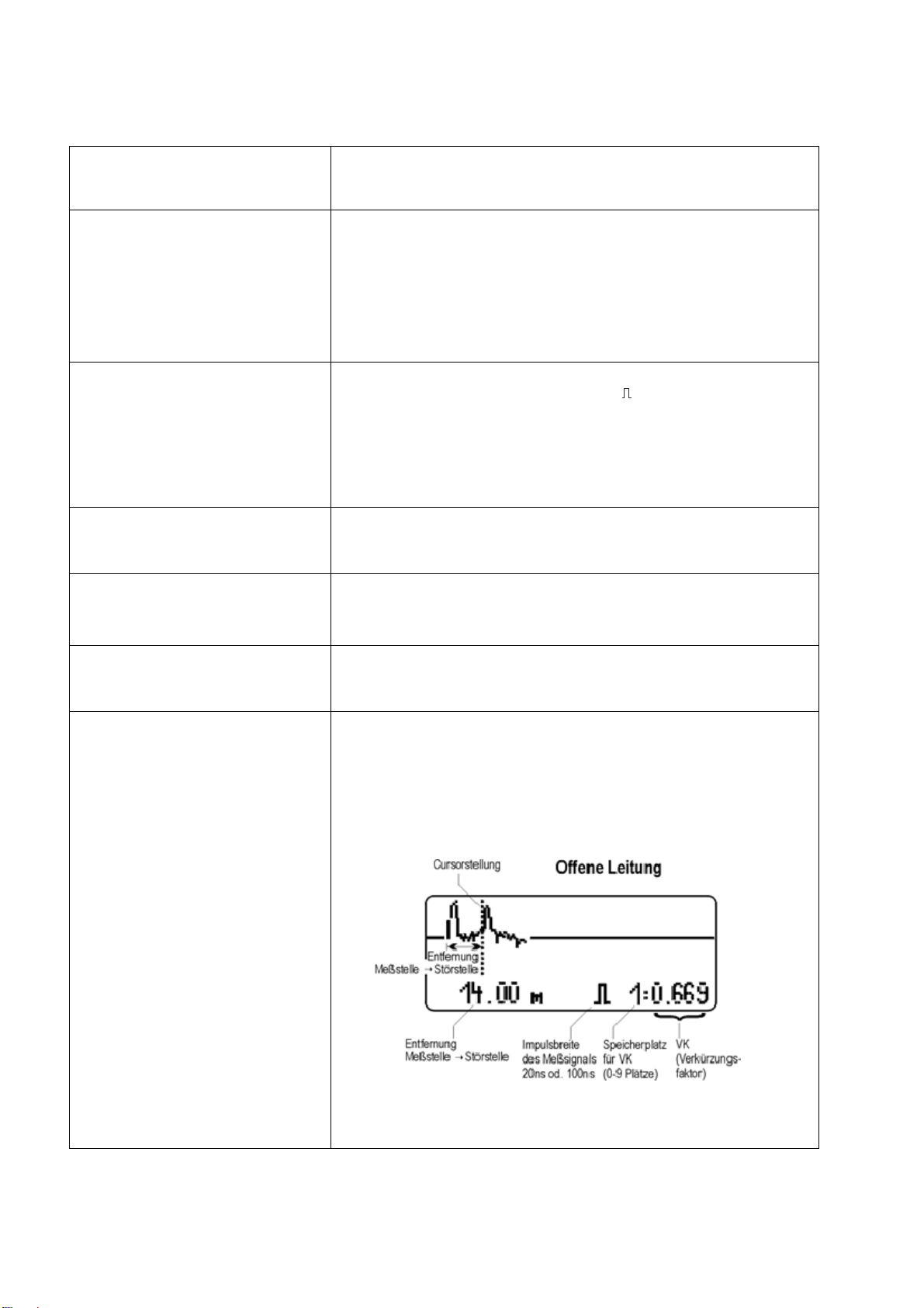
3.1.2 Measuring principle
The instrument works in the time domain. It is to be thought of as an enclosed radar system.
The measurement pulses fed into the cable are reflected by the inhomogeneities of the cable
impedance (cable defects) and shown on the display.
From the shape and the time offset of the reflection it is possible to determine the nature of the
defect and the distance to the defect.
The shortening factor (or pulse speed) indicates how fast electrical signals propagate in a cable in
relation to the speed of light. The highest speed of propagation is achieved in the air with a
shortening factor of 1.00.
The shortening factor of the cable being investigated must be set before commencing to measure
the length. If the factor is unknown, set an approximate value and determine the defect from both
ends of the cable.
In order to determine an unknown shortening factor (SF) value precisely, cut the cable to exactly 10
metres with a tape measure, and change the SF on the measuring instrument during the
measurement process until it shows exactly 10 metres.

Chapter 3 - Startup
232 - V 3.11.4
5
3.2 Operation
Key 1 (LEFT) = DOWN
Key 2 (CENTER) = UP
Key 3 (RIGHT) = MODE
POWER ON - Press key 1. When you press the button, the instrument name
and software button are displayed briefly, and then the battery
voltage is shown for 5 seconds. (full battery approx. 6.4 V, low
battery < 5.9 V
- While the battery voltage is displayed, press key 3 and the unit
is powered on (length display mode) .
- You can select a cable when the instrument is switched off by
pressing key 1 and then key 2. Use keys 1 or 2 to select the
cable type and then press key 3. Press key 3 to switch from the
length display to the return loss measurement (the shortening
factor and cable loss/100 m at 50 MHz are preset for the
measurement.
POWER OFF - Press key 2 and 3 simultaneously, the unit shuts down.
- Automatically after 4 min of not actuated.
- When the battery voltage drops to 5.9 V, this is shown in the
display. At 5.5 V, the instrument shuts down.
SELECT MEASUREMENT
RANGE / PARAMETERS - Briefly press key 3. The cursor is activated (highlighted).
- Selected the measurement range with key 1 and 2.
MOVE CURSOR - With key 1 or 2. Fast cursor movement Hold the key down.
- Switchover of the measurement range is automatic when the
cursor crosses a band limit.
SELECTING VARIOUS
SETTINGS:
LENGTH RANGE
RESOLUTION
OUTPUT PULSE WIDTH
DIGITAL FILTER
MEMORY LOCATION
SHORTENING FACTOR
- Press and hold key 3 (0.5 seconds) until the symbol required is
highlighted.
- Press keys 1 and 2 to change the value selected.
- Press keys 1 and 3 simultaneously to permanently save the
width of the output pulse and the shortening factor.
- To return to the default setting , press key 3 briefly.
RETURN LOSS
(REFLECTION LOSS dbRL)
DETERMINING
- Position the cursor on the echo pulse peak and read out the
return loss at the bottom left of the display.
- The cable loss/100 m at 50 MHz is shown in the cable
selection at the bottom right of the display and must be set in
accordance with the cable data sheet (see attachment). If the
cable loss is set correctly, the instrument displays the actual
(local) return damping.
- The cable's pulse attenuation is deducted and the pulse
amplification is adjusted automatically.
- A pulse width of 20 ns (medium pulse) is best suited for
measurement.
DIGITAL FILTER - In order to suppress or minimise interference in the curve
displayed due to external voltages on the cable, a digital mean
filter “Fi” can be activated using keys 1 or 2. The curve display
is then extended to 3 seconds.
PULSE AMPLIFIER SETTING - Press key 3 briefly and set the amplification with keys 1 or 2.

6Chapter 3 - Startup
232 - V 3.11.4
DETERMINE SHORTENING
FACTOR OF CABLE - Connect a cable (eg 10 or 100 m).
- Set the cursor to the cable length and alter the shortening
factor until the pulse echo is behind the cursor.
CHANGING THE SAVED CABLE
TYPES - Press keys 1 and 2 simultaneously for 5 seconds until the
cable types are displayed.
- Choose the memory location using keys 1 and 2.
- Select the value to be changed with key 3 (highlighted), and
use keys 1 and 2 to change it.
- You can lock unrequired memory locations using ON/OFF (via
the memory location number).
- Press keys 1 and 3 simultaneously to save.
Zero adjustment of transmission
pulse
(only possible from storage)
- Select a storage location for shortening factor.
- Press key 1 and 2 same time until < > is appears on the
display.
- Adjust impulse with key 1 or 2 until the cursor is placed at the
impulse start.
- Storage of this with pressing key 1 and 3 at the same time.
- Back to initial state with key 3.
SAVING THE SETTINGS - Press keys 1 and 3 simultaneously to save the settings
preselected in the display. They are then available when the
instrument is switched on.
LOW BATTERY WARNING AND
SHUTDOWN - If the battery voltage drops to 5.9 V, the voltage is shown
flashing at the top right of the display.
At < 5.5 V the instrument shuts down.
CHARGE - Plug-in power supply (12 - 24Vdc or Vac) on charge socket
5.5/2.1mm, plus inside (12 – 28V)
- Charging time approx. 14 h.
FAULT LOCATION - Connect the cable to device, select the measurement range
and evaluate the diagram. The transmit positive pulse can be
seen at the beginning at 0 m. If the connected cable end is
open, an additional positive pulse appears on the display
(pulse-echo).
- Position the cursor on the start of the pulse and read the length
of the cable.
- For a shorted cable end there is a negative pulse, which is
reflected from the end of the cable.

Chapter 3 - Startup
232 - V 3.11.4
7
FOULT LOCATION - Position the cursor on the start of the pulse and read the length
of the cable.
- If a fault-free cable is terminated with a resistance identical to
the wave resistance of the cable, no reflection is observed.
- If there are interruptions, contact defects on joints, pinches,
shorts or branches/splitters in the region investigated, the
length to the beginning of the cable can be determined from the
pulse echos.
If a wide output pulse is used for measurement, the pulse
echos are more pronounced. Defective branches and splitters
then produce stronger pulse echos.
SHORTENING FACTOR Coaxial cable with PE dielektric 0.66
Coaxial cable with foam PE 0.82 (0.78 – 0.95)
Stripline with foam insulation 0.83
Coaxial cable with air insulation 0.9 (0.88 – 0.92)
Electric cable 0.49 – 0.57 (ca. 0.53)
Attention! The shortening factor is stored by simultaneous pressing of the keys 1 and 3.
When storing the shortening factor the factor must be indicated inverted on the display.
Do not measure on live lines. Voltage strength max. 65 Vdc..

8Appendix
232 - V 3.11.4
Appendix
Cable types
Delivery condition – Stored in EEPROM.
Program
position Cable type
name Cable diameter Type of
dielectric Shortening
factor Cable loss over
50 MHz at 100m
Inner
conductor Dielektric
P1 Mini cable 0.41 mm 1.90 mm CPE 0.78 10.9 dB
P2 H 123 0.65 mm 2.90 mm CPE 0.85 7.5 dB
P3 H 121, MK 75 0.80 mm 3.50 mm CPE 0.84 5.7 dB
P4 MK 15, LCD 90 1.02 mm 4.40 mm CPE 0.85 4.3 dB
P5 COAX 12 0.70 mm 4.60 mm PE 0.66 5.6 dB
P6 H 126 DUOBOND PLUS, KOKA 799 1.00 mm 4.60 mm CPE 0.82 4.5 dB
P7 75100 AKZ 3-5 (RG6) 1.00 mm 4.60 mm CPE 0.85 4.4 dB
P8 LCD 95, DIGITAL 94 1.13 mm 4.80 mm CPE 0.85 4.3 dB
P9 COAX 6 (LG) 1.70 mm 6.95 mm CPE 0.89 2.3 dB
P10 LCM 14, MK 15, KOKA 7 1.63 mm 7.20 mm CPE 0.84 2.8 dB
P11 TELASS B1.1 / 7.3 1.10 mm 7.25 mm PE 0.66 3.8 dB
P12 PRG 11 1.55 mm 7.25 mm CPE 0.81 2.7 dB
P13 1 ikx 1.1 / 7.3; KOKA 741 1.10 mm 7.30 mm PE 0.66 3.3 dB
P14 1 nkx 2.20 mm 8.80 mm PEH 0.88 1.8 dB
P15 75-7-12 D 2.60 mm 10.00 mm AIR 0.85 1.6 dB
P16 COAX 4 2.20 mm 10.20 mm CPE 0.82 1.9 dB
P17 1 qkx 3.30 mm 13.50 mm PEH 0.88 1.2 dB
P18 75-7-16 D 3.80 mm 13.80 mm AIR 0.92 1.1 dB
P19 COAX 3 3.40 mm 14.90 mm CPE 0.84 1.3 dB
P20 1 skx 4.90 mm 19.40 mm PEH 0.88 0.9 dB
P21 Electric cable 0.00 mm 0.00 mm 0.53 5.0 dB
Table of contents
Other KWS Electronic Measuring Instrument manuals