10
11 12
9
SPI-300 - Basic Handling SPI-300 - Basic Handling
SPI-300 - Basic Handling SPI-300 - Basic Handling
1.3 - Entering Data
Three different types of elements may be presented on the screens to enter
adjustment or selection data:
- "Numerical field" : As the name indicates, this element admits only numerical data.
Modification of a number (value of parameter) may be carried out in three different
ways:
a) Digit by digit. Place the slide on the digit you want to change (the slide is moved
using keys ← and → ) and then press repeatedly the key ↑or ↓ until the
desired digit appears.
b) Changing the number complete. Place the slide on the first digit of the number
you want to change and then enter the new number complete through the
keypad. The key "C" is used to delete a wrong digit.
c) Using increments. Place the slide on the right of the number you want to change
and then press repeatedly the key ↑( ó ↓). Each time the key is pressed the
number is changed by a preestablished amount. If the key is held pressed, the
change is effected fast.
- "Slide Icon" : This element is used to modify without precision the value of a
parameter, by moving left-right the slide over a group of vertical bars which serve as
reference for setting.
- "Pick list" : Is a element that contains a folded list. When you select it (SEL
command), the choices of the list are displayed. Then you can select a choice. (With
the keys ← and →you can browse through the pages of the list).
●2→48.25MHz
3→175.25MHz
4→471.25MHz
← 5→519.25MHz ↵
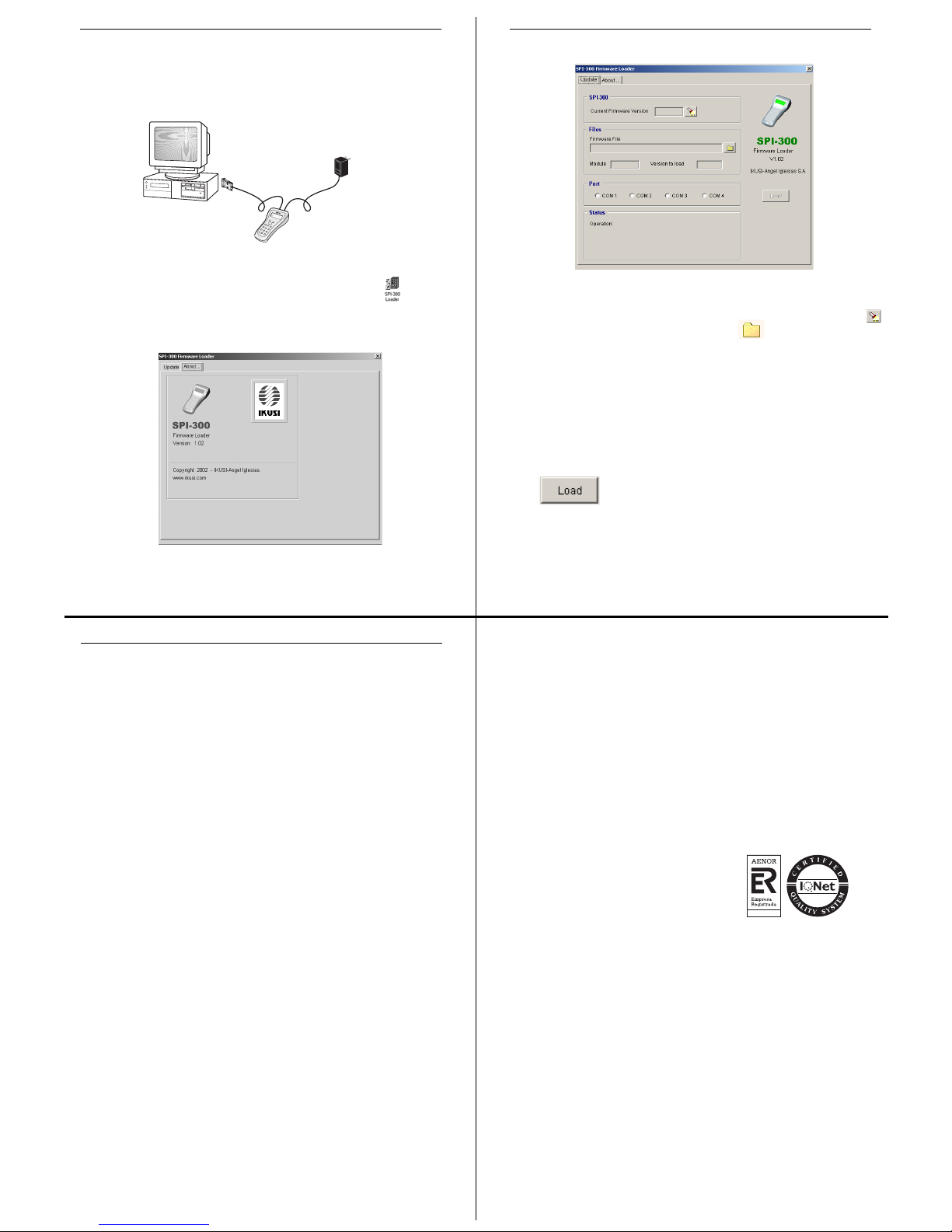
2. PROGRAMMING THE MODULES
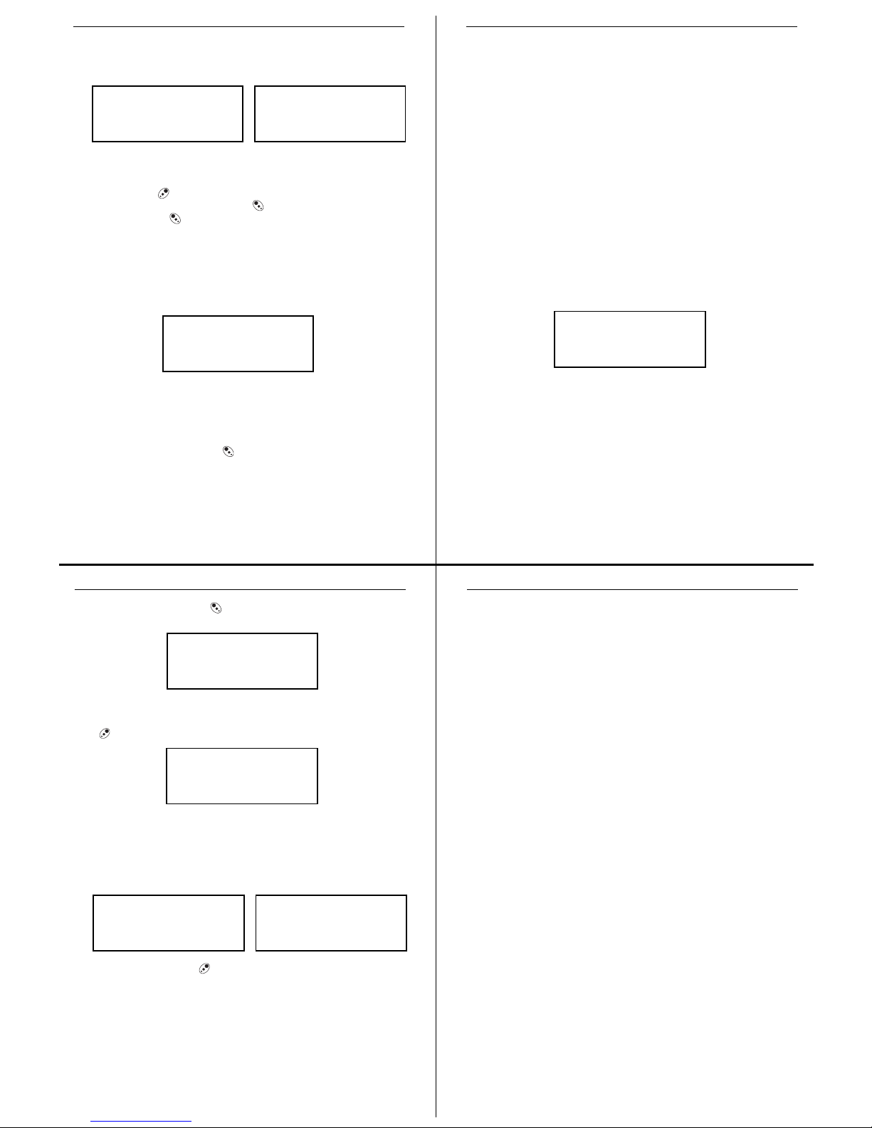
2.1 - Connecting the SPI-300
The modules of a headend are programmed one
by one through individual connections to the
SPI-300. To begin the programmation of a
module, first power it and then plug the cable of
the programming unit into the CONTROL
socket.
V
LNB
QPSKIN
SYNCSTATUS
VIDEO
+12V
RFOUT
IKUSUP
CONTROL
SDC-M201
DIGITALSATELLITE
RECEIVER
SPI-300
2.2 - Detection of the Module
When you connect the SPI-300 to the module, all data for identification, configuration
and status of the module are loaded on the SPI-300. A detection screen appears for a
short time, and next the display shows the Basic Information screen, which identifies
the module and presents its most representative configuration and status data.
The screen closes using the OK command (key ). The Main Menu Screen
appears (page 8); through the Settings and Info menus you can know in detail all
current configuration and status data of the module.
If because of any circumstance the module has not been detected (it is not powered,
there is a failure in the connection to the SPI-300, ...) the following error screen
appears:
Close the screen by using the OK command. The Main Menu Screen appears. In this
case —module not detected— the unique menu is General, which contains only the
Detect and About Of commands. To perform again a module detection operation,
choose the Detect command..
ATTENTION
No module has been
detected
OK
SRF-112 Alarm:No
F01.02 Audio: A2
B05.17 BER: 1.02E-7
Acq:X Vid:X Aud:X OK
2.4 - Looking Up Information
From the Info menu you have access to detailed information about the connected
module, regardless it has been programmed or not. Information is shown throughout
three or more screens, each one related to a menu option. There are three available
options for every module:
–Status : Displays the module working conditions.
–Alarms : Reports what alarms are active and the type of them.
–Details : Identifies the module and displays outstanding data.
The information is periodically updated. To close the screen, use the OK command
(key ).
2.5 - Using Module Configurations
A Module Configuration is a collection of parameter values and use options. Working
with configurations allow to quickly load repetitive data in different modules: instead of
entering, one by one, the setting values for all the parameters and use options, you
can enter a configuration by using a simple command. The SPI-300 allows to create,
and to use later on, up to 500 different configurations for each type of module; for this,
it utilizes the two following functions:
a) Save Configuration: All parameter values and use options which are currently in
the RAM of the SPI-300 (those displayed throughout the Settings menu after
using the SEND or DONE commands) are stored in a register of the
programming unit, with a configuration name which is assigned by the user.
b) Recall Configuration: The parameter values and use options that correspond to a
configuration are loaded onto the RAM of the SPI-300. Then they can be
established in the module by using the SEND command.
Both functions are chosen from the Save and Recall options of the General menu:
1Status
2 Alarms
3 Details
ESC SEL
STATUS
Acq:X
Vid:X BER: 1.02E-3
Aud:X OK
4 Attenua :
SEND SEL
1Frequency : 1550
2 SymbolRate : 27.500
←↵
2.3 - Parameter Setting
The parameter setting is carried out all the Settings menu long. This menu presents,
throughout several screens, the module's parameters grouped by sections or
categories.
Regardless the module type is, the setting process is as follows:
1. In the Settings menu, select the category of the parameters to be set (Input,
Output, V/A Selections, ...).
2. Enter the setting values.
3. Send the set values to the module by using the SEND command at the left lower
corner of the screen (key ).
4. Select, if necessary, other parameter category and repeat the previous operations
as far as all the parameter values have been set.
NOTE: Each time you use the SEND command, you send to the module not only
the values you have modified in the present screen, but also all the values modified
in the previous screens. Remember that the SEND command is also available in
the General menu (page 8).
Nevertheless the process described, some parameters are set in real time, i.e. the
values entered are transmitted instantaneously to the module (you have not to use the
SEND command). It occurs, for example, with the "Modulation Depth" and "Audio
Level" parameters:
If after entering new setting values you use the DONE command (left lower corner of
the screen) instead of the SEND command, these values are not sent to the module,
but they are stored in the RAM memory of the SPI-300. If you use the CANCEL
command, the screen closes without having effect the parameter values previously
entered.
The software controls the setting values you enter, in such a way that an error
message is displayed if these values are not appropriated. The message appears just
when you try to make effective these values using the SEND or the DONE commands.
1 Frequency : 175.25
2Ch: Wrong Value!
3 TV System: B/G
CANCEL SEL
7 NICAMlv :
8MoDepth :
9 AuLevel :
SEND SEL