IKUSI HTI-404 User manual

Web Interface guide
HTI-404
REF. 3864

2
Web Interface guide HTI-404

3
Web Interface guide HTI-404
Index
1. INTRODUCTION ....................................................................................................................................4
1.1 General safety instructions ...........................................................................................4
1.2 Installation enviroment recommendations ............................................................. 5
1.3 Description of the module HTI-404 .............................................................................5
2. HEADEND CONNECTION .................................................................................................................. 6
3. COMMUNICATION WITH THE HEADEND ..................................................................................... 6
4. WEB INTERFACE ..................................................................................................................................7
4.1 Headend .............................................................................................................................. 7
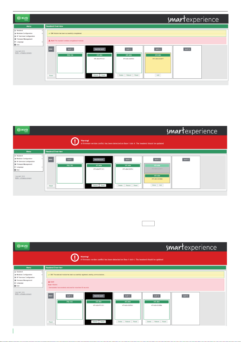
4.1.1 Overview...............................................................................................................7
4.1.1.1 Registering process ............................................................................9
4.1.1.2 Reboot and reset................................................................................11
4.1.2 General configuration.....................................................................................11
4.1.2.1 Site identification................................................................................11
4.1.2.2 Password..............................................................................................11
4.1.2.3 Internet access....................................................................................12
4.1.2.4 Country..................................................................................................12
4.1.2.5 LNB and multiswitch.........................................................................12
4.1.2.6 Autoscan DTT inputs .........................................................................13
4.1.2.7 Configuration backup........................................................................14
4.1.3 Headend DVB network ...................................................................................14
4.1.3.1 Output network configuration ........................................................15
4.1.3.2 Modules in network...........................................................................16
4.1.4 Installation report ............................................................................................16
4.2 Modules configuration...................................................................................................17
4.2.1 Inputs...................................................................................................................17
4.2.2 Outputs................................................................................................................20
4.3 RF services configuration ............................................................................................22
4.4 Firmware management................................................................................................29
4.5 Language...........................................................................................................................30
4.6 Exit ......................................................................................................................................30
5. EQUIPMENT RECYCLING .................................................................................................................31

4
Web Interface guide HTI-404
1. INTRODUCTION
This document explains how to perform the installation of a headend based on HTI-404 modules.
The document describes how the headend is configured. For that, initially the physical mounting is descri-
bed. After that, it explains how to connect the user pc to the headend through IKUSI HEADEND DISCOVERY
application. Finally, all the menu options of the web interface are described.
To ensure the correct use and installation of the headend, it is necessary to read the user manuals and the
installation manuals of the modules included in their own packages.
1.1 General safety instructions
Read all of this user manual carefully before plugging in the unit.
Always have these instructions to hand during installation.
Follow all of the instructions and safety notices regarding unit handling.
Danger of death or injury
This safety notice indicates a possible danger for the life and health of people. Not following
these instructions may lead to serious consequences to health and may even cause fatal
injuries.
Do not install the unit during an electrical storm. This could lead to electrostatic discharge from
lightning.
Do not open the unit. There is a risk of electrostatic discharge.
Risk of damage to the unit
This safety notice indicates a possible dangerous situation. Not following these instructions
may lead to the unit being damaged.
The unit must be appropriately ventilated. Install the unit in a dust-free location. Do not place
the unit in a location where the ventilation slots are covered or blocked. Install the unit in a
location with at least 20 cm around it free of other objects.
Do not expose the unit to rain or moisture. Install the equipment in a dry location with no
infiltration or condensation of water. Should a liquid enter the unit, disconnect it immediately
from the mains.
Keep the unit away from flammable objects, candles and anything that may cause a fire.
Connect the unit to an easily accessible power socket. In the event of an emergency, it will then
be possible to quickly unplug the unit.
Do not expose the unit to sources of heat (sun, heating, etc.).
Handling the inside of the unit is forbidden
This notice forbids any work that may aect the working order of the unit or its warranty
Do not dispose of as urban waste
This type of notice indicates that the unit must not be disposed of as unselected urban waste.
NOTE: This type of notice is a note containing applicable advice and useful information for optimum use of the unit.
DANGER
ATTENTION

5
Web Interface guide HTI-404
1.2 Installation enviroment recommendations
The headend is for indoor use only.
Do not plug in the headend in moist rooms.
Never operate the headend immediately after moving it from a cold location to a hot location. When the
device is exposed to such a change in temperature, moisture may condense on the crucial internal parts.
The device must have sucient ventilation and may not be covered.
Protect the device against direct sunlight, heat, intense temperature fluctuations and moisture. Do not place
the device in the vicinity of heaters or air conditioners.
Do not allow liquids to enter into the device. Turn o the device and disconnect it from the main supply if
liquids or foreign substances end up inside the device.
If the device gets too hot or emits smoke, shut it down immediately and unplug the power cable. Arrange
for your device to be investigated by a technical service centre.
Under the following conditions, a layer of moisture can appear inside the device which can lead to mal-
functions:
if the device is moved from a cold to a warm area;
after a cold room is heated;
when this device is placed in a damp room.
The device should not be used in a very dusty or saline environment. Dust or salt particles and other foreign
objects may damage the device.
Do not expose the device to extreme vibrations. It may damage the internal components.
1.3 Description of the module HTI-404
PSU-150
STATUS
OUTPUT TEST
OUTPUT
INPUT
INPUT TEST
EXT INPUT
Gain 6 dB
-30 dB
-20 dB
STATUS
HTA-125
GAIN
DVB RF IN
DVB RF OUT
STATUS
HTI-404
1
2
3
4
DVB RF IN
DVB RF OUT
STATUS
HTI-404
1
2
3
4
DVB RF IN
DVB RF OUT
STATUS
HTI-404
1
2
3
4
MSS-0512
Ref. 3654
Stand Alone Multiswitch (5 in-12 out)
FREQUENCY RANGE
SAT: 950-2300 MHz
TERR: 5-862 MHz
Input
BACK-500
USB-300
Master module
HTA-125
Router
PSU-150
Slot Nº2
USB-ethernet adapter
for remote or local configuration
1
2
3
4
DVB RF IN
DVB RF OUT
STATUS
HTI-404
1
2
3
4
1 Input (DVB-T/T2/S/S2/C)
2 Control LED
3 Management port (USB)
4 DVB-T/DVB-C output coupling loop

6
Web Interface guide HTI-404
2. HEADEND CONNECTION
The instructions for connecting the headend are described in detail in the guide that is provided with the
HTI module. Also, that guide can be downloaded from our web page www.ikusi.tv.
Briefly, the steps to follow are:
Insert the HTI modules and the PSU-150 power supply in the BACK-500 base-plate. One of the HTI modules
must be inserted in the slot 2 of the base-plate (master module).
Connect the dierent cables from the multiswitch to the module inputs.
Connect the pc to the USB port of the master module, located in the slot 2 of the base-plate, with a
USB-ethernet adapter.
NOTE: It is recommended to use USB-ethernet adapters based on AX88179 or AX88772 chipsets
3. COMMUNICATION WITH THE HEADEND
HTI is configured through a web page generated by the own headend. Use IKUSI HEADEND DISCOVERY application to
access this web page without modifying manually the network configuration of your pc. You can download the IKUSI
HEADEND DISCOVERY aplication from www.ikusi.tv web page.
NOTE: You must use IKUSI HEADEND DISCOVERY version 1.8.5 or higher
Open IKUSI HEADEND DISCOVERY application (the network card IPV6 protocol will be automatically enabled or
permission will be requested to do so).

7
Web Interface guide HTI-404
The window will show the name of the connected master module. Push Configure button and the web
browser of the PC will open automatically, showing the access page of the headend.
NOTE: HTI web interface uses https protocol. It is likely that your browser doesn’t recognize the security
certificate generated by the HTI. To continue configuring the module without problems, add the security
exception requested by your browser in a permanent way.
NOTE: It is recommended to use Mozilla Firefox or Google Chrome as browser.
By default, the language of the web interface is the same than the one used by the browser. If you want to
change it, choose in icon the flag related with the desired language.
Enter the folowing data, User: Admin Password: admin. Push Submit button. The main screen of the
configuration interface will open, from where you can configure the headend, as described in the next
section.
4. WEB INTERFACE
The web interface of the HTI allows to configure the headend, as well as to show status information of the
modules. The following sections describe each of the menu options available.
4.1 Headend
Headend menu, through a series of submenus, allows to display status information and to configure the
global parameters.
4.1.1 Overview
It is the menu that appears by default when entering the headend. The user can access this menu at any
time. To do this, go to Headend Overview. A screen as the following one will be displayed:

8
Web Interface guide HTI-404
This screen shows the whole headend schematically. The essential information of each module inserted
in the base-plate is displayed. The master module always corresponds with the module inserted in slot 2,
and it appears in white on black background. The remaining modules appear on white background.
When selecting a specific module, a window with status information and alarms in detail will open.

9
Web Interface guide HTI-404
In addition, through a series of buttons you can perform the following actions:
To register a module.
To unregister a module.
To clone settings from an old module to a new one.
To reboot a module.
To reset a module with its default settings.
To reset all modules of a headend, loading their default settings.
4.1.1.1 Registering process
The headend only allows to configure those modules that have been registered previously. The unregiste-
red equipments are shown in yellow on white background. By default, no module except the one inserted
in slot 2 (master slot) is registered. To register a module that has been detected by the master module
simply push Add button of that module. The background color change to white indicating that the module
has been properly registered.
Repeat the registration process with all modules you want to include in the headend.
If, for any reason, you want to unregister a module of the headend, you must push the Delete button. The
module will be displayed in yellow background, indicating that has been unregistered correctly.

10
Web Interface guide HTI-404
The registration process is dierent if it is the result of replacing a module (for example, due to failure).
In that case, when placing a new module in the position of one that had been already registered by the
headend, the user can choose between to add it without modifying the configuration of the module or to
copy the configuration of the module that was previously registered in that slot. In the following example,
starting from the previous headend with 3 HTIs, all registered, the HTI of slot 4 has been replaced with a
new HTI:
A module with two possible configurations is displayed: one in grey background, corresponding to the
previous module that was already registered in the headend, and another one in yellow background,
corresponding to the configuration of the new module pending registration.
If you want to copy the settings from the previous module, push Clone button. If, instead, you only want
to register the new module without copying the previous configuration, push Add button. In both cases, as
result a screen will be displayed where the module appears as registered.

11
Web Interface guide HTI-404
4.1.1.2 Reboot and reset
The user can reboot a specific module. To do this, you must push Reboot button of that module.
On the other hand, if you just want to load the default settings of the module, just as it comes from the
factory, you must use Reset button. If you want to load the default settings of a specific module, push
Reset button of that module. However, if you want to load the default settings on all modules of the
headend, you can do it pushing Reset button associated with the Base.
In both cases, a warning message indicating that the module will return to its default settings will be
displayed. Press OK if you understand the consequences of this action and you agree.
NOTE: In the case of resetting the master module, slave devices will be unegistered.
4.1.2 General configuration
This menu displays several tabs that allow to set global parameters of the headend. To access this menu,
go to Headend General Configuration. A window as the following one will open:
4.1.2.1 Site identification
Select the Site Identification tab. In this screen you can introduce information about the headend to distin-
guish this particular headend with respect to others. This information will appear in the installation report.
Introduce the headend name (or ID) and the facility location (free text). You can also specify the date on
which the installation was performed. Push Save button to save the data.
4.1.2.2 Password
To change the password of the headend, select the Password tab.

12
Web Interface guide HTI-404
Follow the instructions on the screen to make the change of the password (enter the old password, enter
the new password and confirm the new password) . Finally, push the Save button.
4.1.2.3 Internet access
If you want to access to the headend through internet, you must set previously the connectivity parame-
ters of the headend. To do that, select the Internet Access tab.
Select Use DHCP for address resolution option if the network settings will be automatically provided by
a DHCP server. Otherwise, unselect this option and manually enter the settings (IP address, Netmask,
Default gateway, Primary DNS Server, Secondary DNS Server). Consult network manager to get those
parameters. Push Save button to save the changes.
4.1.2.4 Country
To set the local time and customize certain parameters related to the specific country regulations (LCN,
NIT, etc.) select the Country tab.
In this screen you can select the date and current time, time zone and the country in which the headend is
installed. To save the changes push the Save button.
4.1.2.5 LNB and multiswitch
Select the LNB and Multiswitch tab to configure the parameters related with the used satellite installation.

13
Web Interface guide HTI-404
In the LNB area, set the parameters of the LNB that you are using (frequency band, local oscillator fre-
quency for low polarity and local oscillator frequency for high polarity).
In the Multiswitch area you can describe how is the Multiswitch that is being used. To do that, introduce the
number of inputs of the multiswitch (in the case there isn’t multiswitch, select 0). For each of the inputs,
defined by its position and grouped in fours, you must identify which polarity is (Vertical or Horizontal) and
in which band is transmitted (Low or High). The headend proposes a name for that input as a combination
of the satellite name, polarity and band. This name can be edited.
Push the Save button to save the changes.
4.1.2.6 Autoscan DTT inputs
The Autoscan DTT Inputs tab allows to enable/disable automatic scanning of DTT inputs in case of a
change in the frequency plan.
Thus, if Autoscan is enabled, when a frequency change is done in a DTT signal that was tuned previously,
the HTI will lose sync and will launch a scan of the inputs, in order to search the new frequency of the
signal (identified with the same TS_ID and SID values).
If the Autoscan is disabled, when a change in the frequency plan happens, the HTI must be reconfigured
manually.
To enable the Autoscan of DTT inputs, push Enable Autoscan button. To disable it, push Disable Autoscan
button. By default, the Autoscan is enabled.

14
Web Interface guide HTI-404
4.1.2.7 Configuration backup
The Configuration Backup tab is used to download or upload a copy of the complete configuration of the
headend. Thus, you can replicate the configuration of a headend over another one (or over the same one, if,
for any mishandling, it reaches to an undesired state).
To download a file with the current configuration of the headend, push the Download button.
To apply a configuration previously stored, first choose the file pushing Select File to Apply button.
After that, push Upload button. A message will appear, indicating configuration is being applied. After
some seconds, the configuration will have been applied and the browser will redirect you to the Site
identification screen.
4.1.3 Headend DVB network
This menu displays two tabs through which the user can configure the parameters associated with the
transmission network. To access this menu, go to Headend Headend DVB Network.

15
Web Interface guide HTI-404
4.1.3.1 Output network configuration
When selecting this first tab, a window as the following one will be displayed:
In this window, the name of the network included in the NIT will be shown, with the value of NID and ONID
that are being used. Pushing , icon, you can download the NIT, SDT and TDT tables on your computer. In
addition, the Status NIT / SDT field will indicate whether the insertion of tables is correct or not.
To configure the parameters related with the NIT table, . icon. A window as the following one will open:
In this window you can configure the following parameters:
•Name: is the network name that will be signalled in the NIT table.
•NID: is the value of the Network Identifier that will be signalled in the NIT table.
•ONID: is the value of the Original Network Identifier that will be signalled in the NIT table.
•Auto Service List: If you don’t want to send the service_list_descriptor, select Disabled. In other case, a
service_list_descriptor with the information of the services broadcasted by the headend will be included
in the NIT table.
•NIT LCN Mode: if youn don’t want to send LCN, select Disabled. In other case, select the LCN mode used
by the TVs of the facility.
•NIT Template: it allows to select the method of generation of NIT in the case of several NITs exist in the
input. The user can choose between three options:
No NIT Template: the headend generates a NIT from zero, based on the selected output fre-
quencies, the output services and the selected LCNs.
Merged NITs: the headend generates a new NIT based on the descriptors of the NIT tables of
the input signals.
Available Input NITs: a new NIT is generated, based on the descriptors of the NIT table of a
specific input.
To save the selected parameters, push the Save button.

16
Web Interface guide HTI-404
4.1.3.2 Modules in network
This tab shows the DVB signaling information of the output carriers of all the modules included in the
broadcasting network.
Push icon to edit the information of a specific carrier. A window as the following one will open:
Edit ONID (Original Network Identifier) and TSID (Transport Stream Identifier) fields with the desired
values for that carrier and push Save button.
4.1.4 Installation report
Installation report option (Headend Installation Report) shows, in a grouped way, all the information of
the headend. In this report you can find:
•Information about alarms, in the case there are any.
•Installation description.
•Language, data, hour and country information.
•Information about IP connectivity.
•Configuration of the LNB and Multiswitch.
•Headend composition.
•Relevant information of each module, such as serial number, sw version, hw version, temperature or
working hours.

17
Web Interface guide HTI-404
•Information about the RF inputs of each module, such as standard, frequency, status, signal strength or
signal quality.
•Information about the RF outputs of each module, such as standard, frequency, available space or
number of services.
•Information about the services that are processed by each module.
4.2 Modules configuration
This menu allows you to configure the inputs you want to receive and the carriers that you want to
transmit.
4.2.1 Inputs
To configure the inputs you want to receive, select Modules Configuration Inputs. A window as the
following one will open:

18
Web Interface guide HTI-404
In this window, the four inputs of each HTI are displayed. To configure one of them, select the icon
associated with that input.
For each input, you must configure if it is enabled or not and what is the reception standard
(DVB-S / S2 for satellite, DVB-T / T2 for terrestrial or DVB-C for cable). The rest of parameters will depend
on the selected standard, in the following way:

19
Web Interface guide HTI-404
DVB-S/S2
•Frequency (MHz): it allows to select the intermmediate frequency value to be received.
•Diseqc input: it allows to select the multiswitch signal (or the LNB signal) to be received.
•Sat. Frequency Transponder (MHz): it allows to select the frequency value of the transponder to be
received. By modifying this parameter, the value of the Frequency field is automatically updated and
vice versa.
•Advanced parameters: it allows to show or hide the advanced parameters related to the reception of
multistream signals. They are the following:
PLS Mode: choose between Auto, Root or Gold modes.
Scrambling ID: enter the scrambling identifier related to the selected PLS mode (it does not appear
with PLS Auto Mode).
Stream ID: choose the specific stream of the multistream signal that you want to receive.
DVB-T/T2
•Frequency (MHz): it allows to select the frequency value of the multiplex to be received.
•Bandwitdth (MHz): it allows to select the bandwith of the multiplex to be received.
•Advanced parameters: it allows to show or hide the advanced parameters related to the reception of
DVB-T/T2. They are the following:
Hierarchy: in broadcasting with several hierarchies, it allows to select the hierarchy of the signal to
be received.
Autoscan: it allows to enable or disable the automatic scan of the DTT inputs in case of a change in
the frequency plan.
PLP ID: choose the specific PLP that you want to receive in the case of a signal with multiple PLPs.
DVB-C
•Frequency (MHz): it allows to select the frequency value of the multiplex to be received.
•Constellation: it allows to select the constellation of the input signal. In the case it is configured as
"Auto", the module will detect the constellation automatically.
•Symbol Rate (Kbaud): it allows to select the symbol rate of the multiplex to be received.
Once the parameters of each input have been selected, push icon to save the changes. If, however,
you want to discard them, push icon.
Tuning status (Locked or Unlocked) will appear in each of the inputs. Also, an icon indicating the level
of signal and its quality, where red is bad quality, yellow medium quality and green good quality, will be
displayed.

20
Web Interface guide HTI-404
4.2.2 Outputs
To configure the output carriers you want to transmit, select Modules Configuration Outputs. A window
as the following one will open:
In this screen the output configuration of each module is displayed. This configuration is divided into two
parts: a global part associated with the module and another part associated with each of the carriers.
In the global configuration, the output standard (DVB-T or DVB-C) and output attenuation (using a scroll
bar) will be selected.
In the configuration associated with the output carriers, the four outputs of each HTI are shown. To confi-
gure one of them, select the icon associated with that output.
Table of contents
Other IKUSI Control Unit manuals
Popular Control Unit manuals by other brands

Delabie
Delabie 510140 quick start guide

Cooper Crouse-Hinds
Cooper Crouse-Hinds eLLK 92 NIB Series Supplementary instructions

Nice
Nice MNCUT Instructions and warnings for installation and use

b&t
b&t BW16-Kit specification

Cisco
Cisco NM-1E2W Configuration note

Wenglor
Wenglor SR4D3B01S operating instructions

Spirax Sarco
Spirax Sarco 25E Installation and maintenance instructions

TECO
TECO Tecomat Foxtrot OS-1401 Basic documentation

Danfoss
Danfoss VCM 46 Service guide

Nexcom
Nexcom NEIO-B1812 Quick reference guide

Canford
Canford 58-321 Technical data sheet

Zurn Wilkins
Zurn Wilkins 375 Installation, Testing, Maintenance Instructions