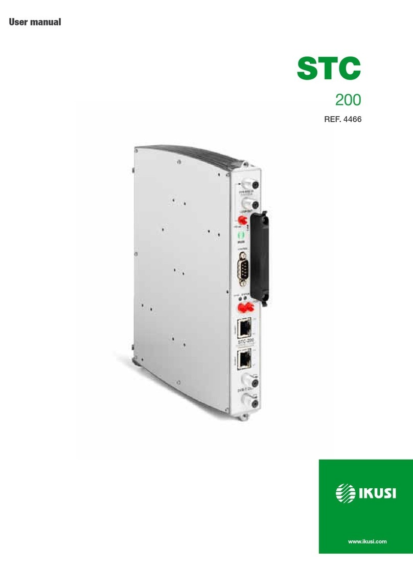
IKUSI STC 100 User manual

User Manual
STC
100
REF. 4465


4 General safety instructions
4 Types of notices
5 Basic safety instructions
6 Introduction
6 General description
7 General use of the headend
8 Basic installation and configuration
8 Assembly, connection of signals and power supply
9 Description of the user interface
10 IKUNET bus configuration
14 Configuration of general parameters
15 Module configuration
20 Service Management
23 Advanced functions
23 Save/Restore Function
23 Internet Access
24 Network functions
25 Advanced global transport processing
26 Reports
30 CE Certificate
30 STC-201
Contents

4
General safety instructions
JRead all of this user manual carefully before plugging in the unit.
JAlways have these instructions to hand during installation.
JFollow all of the instructions and safety notices regarding unit handling.
Types of notices
The meaning of the safety notices used in this manual are described below.
DANGER OF DEATH OR INJURY
This safety notice indicates a possible danger for the life and health of people.
Not following these instructions may lead to serious consequences to health and
may even cause fatal injuries.
RISK OF DAMAGE TO THE UNIT
This safety notice indicates a possible dangerous situation. Not following these
instructions may lead to the unit being damaged.
NOTE
This type of notice is a note containing applicable advice and useful information
for optimum use of the unit.
HANDLING THE INSIDE OF THE UNIT IS FORBIDDEN
This notice forbids any work that may affect the working order of the unit or its
warranty.
DO NOT DISPOSE OF AS URBAN WASTE
This type of notice indicates that the unit must not be disposed of as unselected
urban waste.
DANGER
ATTENTION

General safety instructions/Basic safety instructions
5
Basic safety instructions
DANGER OF DEATH OR INJURY
JDo not install the unit during an electrical storm. This could lead to electro-
static discharge from lightning.
JDo not open the unit. There is a risk of electrostatic discharge.
RISK OF DAMAGE TO THE UNIT
JThe unit must be appropriately ventilated. Install the unit in a dust-free
location. Do not place the unit in a location where the ventilation slots are
covered or blocked. Install the unit in a location with at least 20 cm around it
free of other objects.
JDo not expose the unit to rain or moisture. Install the equipment in a dry lo-
cation with no inltration or condensation of water. Should a liquid enter the
unit, disconnect it immediately from the mains.
JKeep the unit away from ammable objects, candles and anything that may
cause a re.
JConnect the unit to an easily accessible power socket. In the event of an
emergency, it will then be possible to quickly unplug the unit.
JDo not expose the unit to sources of heat (sun, heating, etc.).
DANGER
ATTENTION
EN

Introduction/General description
6
Introduction
JTo ensure the correct use and installation of the headend, it is necessary to read the
user and troubleshooting procedure manuals corresponding to the complete solution
and to each of the individual modules.
JIKUSI reserves the right to modify the contents of this manual without prior warning.
General description
The headend described in this manual is made up of the following modules:
JSTC-100 (Ref. 4465): DVB-S/S2 to DVB-T transmodulator (QPSK/8PSK to COFDM).
JCFP-507 (Ref. 4439): power supply +12 V/+24 V.
5
6
7
8
1
2
3
4
9
10
11
12
13
14
15
16
STC-100
KEY
A STC-100 module
B CFP-700 module
C CFP-507 module
1 Input 1 DVB-S/S2 channel
2 Loop output
3 LNB remote power supply
4 Slot for CAM
5 DB-9 port
6 DC power supply
7 RJ-45 ports for IKUNET bus
8 Coupling loop DVB-T output
9 Output +12 V (5 A)
10 Output +24 V (60 mA)
11 Output +18 V/22 kHz (300mA)
12 Output +13 V/22 kHz (300mA)
13 Output +18 V/0 kHz (300mA)
14 Output +13 V/0 kHz (300mA)
15 Output +12 V (7 A)
16 Output +24 V (60 mA)

7
Introduction/General use of the headend
7
JCFP-700 (Ref. 4401): power supply +12 V/+24 V for selection of polarisation.
JBAS-900 (Ref. 4411): base-support with capacity for 9 modules (dimensions:
563x257x24 mm).
JMS-0504 (Ref. 1023): stand-alone multiswitch (4 SAT inputs and 4 outputs).
NOTE
Please read the detailed information in the manuals for the modules included in
their respective packaging.
General use of the headend
This headend is designed for the emission of DVB-T (COFDM) signals from the input of free
or encrypted DVB-S/S2 signals (QPSK/8PSK to COFDM).
NOTE
The DVB-T (COFDM) output signal requires a trunk amplier for the correct distri-
bution in installations for a large number of sockets.
ENEN

Basic installation and configuration/Assembly, connection of signals and power supply
8
Basic installation and configuration
NOTE
A PC with an Ethernet network card and a CAT-5E Ethernet crossover cable are
required for communication with the headend.
NOTE
To display the graphics provided in the headend conguration program correctly,
we recommend installing the Mozilla Firefox web browser (www.mozilla.com) in
the control PC.
Assembly, connection of signals and power supply
1) Attach the modules to the base one by one following the instructions given in the
manuals for each module.
NOTE
IKUSI recommends the modules are assembled in the order shown in the above
gure:
JRight: CFP-700/CFP-507 power supplies.
JLeft: STC-100 transmodulators
13
2
654
KEY
1 DVB-S/S2 signal input
2 DVB-T signal output
3 Bridging line in loop mode
4 Power supply bridges
5 IKUNET
6 CAM + SmartCard + protection with safety
screws

9
Basic installation and configuration/Description of the user interface
JLast STC-100 on the right: Master STC-100 with the DVB-T output signal.
2) Connect the input and output signal connections in accordance with the instructions
for the module manuals and the diagram shown in the previous gure.
3) Distribute the headend power supply as symmetrically as possible (see example in
above gure).
Description of the user interface
The interface permits the user to communicate easily and comfortably with the headend.
The layout of the menus and submenus of the interface is shown in the following diagram:
The upper part of the interface displays messages about the communication status with the
headend. Each message is colour-coded:
FGreen: noties that the instruction has been carried out.
FRed: indicates that the instruction could not be performed and gives the reason.
KEY
1 Exit button
2 Information button
3 Print button
4 Main menu
5 Submenus
6 Tabs
7 Status message
8 Work area
EN

10
Basic installation and configuration/IKUNET bus configuration
IKUNET bus configuration
The IKUNET bus is an Ethernet communication bus between the headend modules. The
IKUNET bus is installed using Ethernet pigtails supplied with the modules. If n is the
number of station modules, n-1 Ethernet pigtails are required.
Definition of the master module
NOTE
JRemember the PC conguration prior to the connection with the IKUNET
bus.
JThe denition of the master module must be made with an STC-100 module.
NOTE
In mixed STC and MTC congurations, an STC module may never be an MTC
module master. In these cases, the master module must be an MTC module and
the STC modules are reserved for conguration as slave modules.
1) Start the conguration of the IKUNET bus for
the headend with the modules disconnected
from each other.
2) Connect the selected module ( A ) to the PC ( B
) via its Ethernet connection and using an RJ-45
cable ( C ).
3) In the PC (Windows XP) go to
.
4) Select the
checkbox. Enter the following IP con-
guration parameters:
F: 10.254.254.2
F: 255.255.255.0
F: 10.254.254.1
5) Click on the button.
6) Enter the IP address http://10.254.254.254 in the web browser. This takes you to the
home page of the connected module.
STC-100 STC-100

11
Basic installation and configuration/IKUNET bus configuration
7) In the home page of the selected module,
“Admin” appears by default in the eld.
Enter the word “admin” in the eld
and click on .
8) The main management window for the STC-100
module as slave module is displayed.
NOTE
The module with which you have con-
nected the PC disconnects automatically
after 15 minutes without interaction.
9) In the main menu, click on Master
. The
window is displayed, with the tab.
10) Enter the name of the module in the
eld.
NOTE
IKUSI recommends you give a description
to the module according to its position
in the headend in order to identify the
modules logically and physically. For
example, for a conguration identical to
that proposed in the assembly section, in-
clude the following identications (on the
base, from right to left:
).
11) To activate the module as master of the head-
end, click on the checkbox. The module
will be congured as master once the window has been saved.
CAUTION
If the background of the eld is red, this means that the data has been modi-
ed but has not yet been saved. Before changing to another window or tab, any
modied data must be saved (click on ). Otherwise, the modied data will
be lost and the previous information state will be maintained in the headend.
NOTE
If the IKUNET bus is connected to another Ethernet bus, we recommend you limit
the IP range to the number of slave modules in the IKUNET bus, so that these
can be identied more easily.
12) Click on in the main screen (top right corner).
EN

12
Basic installation and configuration/IKUNET bus configuration
Name of slave modules
Continue without connecting the IKUNET bus.
Follow the steps below for each of the remaining modules of the headend (slave modules).
1) Connect the selected module ( A ) to the PC
(B) via its Ethernet connection and using an
RJ-45 cable ( C ).
2) Enter the IP address http://10.254.254.254 in
the web browser. This takes you to the home
page of the connected module.
3) In the home page of the selected module,
“Admin” appears by default in the eld.
Enter the word “admin” in the eld
and click on .
4) Enter the name of the module in the
) eld.
CAUTION
The checkbox must be left un-
marked for the slave modules
5) Click on
6) Click on in the main screen (top right corner).
General configuration of the headend
When the master module for the headend has been dened, access to the headend is via
the master module. To access the master module it is necessary to congure the IP access
of the PC and enter another IP address in the web browser.
1) Connect the IKUNET bus for the headend with the Ethernet pigtails supplied together
with each module (see example in the gure in the General description section).
2) In the PC, modify the IP address, following the same steps as in Definition of the
master module, but including the following parameters:
F: it should follow the root of the IP address for the master module of
the headend, but be out of its range. The address recommended by IKUSI for the
default conguration of the master module is 192.168.1.2.
F: 255.255.255.0
F: 192.168.1.1
3) Click on the button.
4) In the web browser, enter the IP address of the master module. The default address is
http://192.168.1.5. This takes you to the home page of the headend master module.
STC-100 STC-100

13
Basic installation and configuration/IKUNET bus configuration
5) In the home page of the selected module, enter
the word “Admin” in the eld.
6) Click on . The main screen of the
master module user interface is accessed
through the
window.
Module registry and name
Proceed as follows to register the modules:
1) Go to the menu
The list of modules con-
nected to the IKUNET bus should appear on the
screen. Each row corresponds to a module. The
recognition status in IKUNET and the module
registry in the conguration of the headend can
be distinguished by the colour of each row:
FBlue: the module has been recognised in the
IKUNET bus but has not yet been registered.
FRed: the module is not recognised in the
IKUNET bus and has been registered previ-
ously.
FLight green: the module is recognised in the
IKUNET bus and has been registered.
2) To register the identied modules, select the
checkbox in the column for all the
modules which form part of the headend and
click on . To delete the registry of a
module which is part of the headend, click on
( ).
3) Name the modules ( column in the list of modules). Proceed as follows, module
by module:
a) Search for the module to be named. Follow
a logical order with respect to the selected
assembly order. Example: follow the mod-
ules tted from right to left: “STC-1” and
“STC-2”).
EN

14
Basic installation and configuration/Configuration of general parameters
NOTE
To identify a module, in the
table click on the
cell corresponding to the MAC address of
the module. The cell will change to a uo-
rescent green colour and the and
control LEDs for the selected
module ash together.
b) Click on the magnifying glass icon of the
module to be named.
c) In the main window of the user interface
go to the
d) Enter the name of the module in the eld.
CAUTION
If the background of the eld is red, this means that the data has been modied
but has not yet been saved. Before changing the window or tab, the modied
data must be saved (click on ). Otherwise the modied data will be lost and
the headend will remain in the same state as before.
Configuration of general parameters
Permits the modication of the basic identication, network and access parameters and of
the headend rmware.
To access from the main menu, click on
J
Fshows the name of the module
model.
Fshows the hardware
identication code.
Fshows the number which
identies the unit for network connection.
Fenter the module name.
Fallows the name of the city in
which the unit is installed to be entered.
Fallows the name of the person installing the equipment to be entered.
Fallows the phone number of the installing company to be
entered.
Fallows the date on which the unit is installed to be
entered.
Fclick on the checkbox on the right to select the module as
master.
F: click on the button to save the changes.
STC-100 STC-100

15
Basic installation and configuration/Module configuration
J:
Fshows the number which
identies the unit for network connection.
Fshows the number of the IP
address.
Fshows the network
mask code.
Fshows the Gateway
IP address.
Fallows the number of the rst IP address in the range of IPs
to be included to be entered.
Fallows the number of the last IP address in the range of IPs to
be included to be entered.
Fclick on the button to save the changes.
Fclick on the button to omit the changes.
J
Fenter the current pass-
word for the home page.
Fenter the new pass-
word.
Fenter the
new password again.
Fclick on the button to save the changes.
Fclick on the button to omit the changes.
J
Freboots the module
in the event of blocking.
Fshows
the number of the current rmware version.
Flist of imported rmware version
numbers.
Fclick on the button to select the
route for the rmware le to be imported.
Fclick on the button to
import the selected rmware le.
Module configuration
Permits the modication of the operating parameters for the multiswitch, the inputs and the
output of the module. To access from the main menu, click on
EN

16
Basic installation and configuration/Module configuration
NOTE
To start the headend conguration, rst dene the master module and the identi-
cation of the slave modules for the headend, as described in the section Basic
installation and configuration.
J
Fclick on the icon to access the module con-
guration.
Fclick on the icon ( ) to display:
of the module inputs and the
Fshows the name of each module.
Fshows the family name of each module.
Fshows the name of the module model.
Fclick on the buttonto identify all the modules.
F: shows the IP of each module.
Findicates the operational status for the module: If it is operating correctly,
the icon ( ) is displayed, otherwise the icon ( ) is displayed.
Fthis indicates whether there is an operating alarm in the module.
Fto register the modules identied, select the checkbox in the
column for all the modules which form part of the headend and click on
: To delete the registry of a module which is part of the headend, click
on ( ).
Fclick on the buttonto update the information on the screen.
Configuration of master STC module
Description of the multiswitch
This permits the modication of the multiswitch operating parameters for the master STC
module. To enter from , click on the magnifying
glass icon of the master module. Go to
J
allows to enter the local oscillator
frequency value for the low band and inform the
master STC module of the presence and charac-
teristics of the multiswitch.
J
allows to enter the local oscillator
frequency value for the high band and inform
the master STC module of the presence and
characteristics of the multiswitch.
Jclick on the dropdown menu to select the number of inputs for
the master module:

17
Basic installation and configuration/Module configuration
FFor a connection without multiswitch, select the “0” value for the master module
inputs.
FFor a connection with multiswitch, select the value corresponding to the number of
multiswitch inputs. Next open the dropdown menu
Ì: name of the input signal to the multiswitch for identication in
subsequent congurations: IKUSI recommends you identify the type of satellite,
polarity and the bandwidth of the signal.
Ìnoties of the multiswitch input being described.
Ìclick on the dropdown menu to select the polarity:
or
Ì: for each polarity select once and once.
Jclick on the button to save the changes.
Configuration of inputs
This permits the modication of the operating parameters for the master STC module
output. To enter from , click on the magnifying
glass icon of the master module. Go to .
J
Fclick on the
dropdown menu to select one of the follow-
ing options:
ÌFor a connection with multiswitch select
the input for the multiswitch to be con-
nected to the STC.
ÌFor a connection without multiswitch
select .
Fclick on the dropdown menu to
select the intermediate satellite band type.
F
permits the frequency value to be selected
for the transponder to be received.
Fpermits the required intermediate frequency value to be
selected.
Fpermits modication of the input speed value.
Fshows if there is an input signal.
Fshows the rate for the bits that were incorrectly received by the input.
Fshows the noise level in the input
signal.
Fshows the percentage power of the input signal with respect to
the maximum possible.
F click on the button to save the changes.
EN

18
Basic installation and configuration/Module configuration
Output configuration
This permits the modication of the operating
parameters for the master STC module output. To
enter from
, click on the magnifying glass icon of the
master module. Go to .
F: permits the value of
the output frequency to be modied.
F : click on the dropdown
menu to select the OFDM transmission
parameter.
F click on the drop
down menu to select the band width value for the output signal.
F: click on the dropdown menu to select the guard interval for
the OFDM signal.
F: click on the dropdown menu to select the digital constellation
layout.
F: click on the dropdown menu to select the FEC coding convolution
code
F: click on the displacement bar to modify the output level of
the signal.
NOTE
The advanced parameters may only be modied in special cases, in the majority
of installations the factory settings should not be changed.
: click on the right-
hand checkbox to display the
menu.
Fclick on the dropdown menu
to select the form (or
) of the I-Q output channel spectrum.
NOTE
To modify the value of the remember that when the band-
width of the COFDM output is reduced, the interference from the adjacent chan-
nel is reduced, but the efciency of the guard interval is reduced proportionally
and may prevent the tuning of the receivers.
Fclick on the horizontal displacement bar to modify the band
width of the COFDM channel output.
Fclick on the horizontal displacement bar to modify the number of cells to
be allocated to the COFDM channel output.

19
Basic installation and configuration/Module configuration
Fclick on the dropdown menu to activate or deactivate the error
correction protocol: This permits errors in the DVB-H transmission to be detected
and corrected.
Fclick on the dropdown menu to activate or deactivate the
timeslicing. If timeslicing is on, the receiver switches off during inactive periods and
consumption for transmission in DVB-H is reduced.
Fclick on the dropdown menu to activate or deactivate the
bit interlacing for the correction of transmission code errors in DVB-H.
Jclick on the button to save the changes.
Jclick on the button to cancel the changes.
Jshows the module temperature.
Jshows the maximum ow of the output signal.
Jshows the percentage of packages received
without information.
Jshows the theoretical signal/noise ratio re-
quired at the base of the socket so that the television receives the signal correctly.
Configuration of slave STC module
NOTE
The operating parameters for the slave STC module inputs and output follow the
same conguration method as the inputs and output of the master STC module.
Input configuration
Allows to change the operational parameters for the slave STC module input. To enter from
, click on the magnifying glass icon of the slave
STC module. Go to .
For a description of the operating parameters of the slave STC module inputs in this
manual, please go to the section Configuration of the inputs.
Output configuration
This permits the modication of the operating parameters for the slave STC module output.
To enter from , click on the magnifying glass
icon of the slave STC module. Go to .
For a description of the operating parameters of the slave STC module output in this
manual, please go to the section Configuration of the output.
EN

20
Basic installation and configuration/Service Management
Service Management
Selection of input services
1) To dene the services to be emitted through the
output of the DVB-T output signal, go to
In
the upper side of the
window there is a table
showing the services available in the input,
differentiated by modules.
2) Click on the icon on the left of the row of each module (position 1 in the above gure)
to go to the list of input services.
a) To select a particular service, activate the checkbox in the column ( 2 ).
b) When all the services of a module have been enabled for the output signal, click
on the button.
KEY
1 Selection of STC module.
2 Selection of service to the output signal (if the
checkbox is not displayed, the service has
already been selected at the output).
3 Service type.
Lock closed = encrypted.
Lock open = free.
4 Service: name of service (contextual menu
when passed with the cursor: information on
Service ID).
5 Input: module input number (contextual menu
when passed with the cursor: information on
Original Network ID and Transport Stream ID).
6 Original LCN. Logic Control Number emitted
by the operator.
Table of contents
Other IKUSI Industrial Electrical manuals
Popular Industrial Electrical manuals by other brands

EUCHNER
EUCHNER ESM-F Series System manual

Murata
Murata GRM0335C1E9R0DA01 Series Reference sheet

Murata
Murata GRM1555C1H9R0CA01 Series Reference sheet

Murata
Murata GRM1885C1HR90BA01 Series Reference sheet

Murata
Murata GRM1885C2A681JA01 Series Reference sheet

Moeller
Moeller NHI-NZM10 installation instructions

Zagar Incorporated
Zagar Incorporated MQ-150 Installation, operation & maintenance manual

Eaton
Eaton DILM17-21 Series Instruction leaflet

Murata
Murata GRM1885C1H1R5WA01 Series Reference sheet

Murata
Murata GRM0225C1E9R8WA03 Series Reference sheet

Murata
Murata GRM0225C1E6R1WA03 Series Reference sheet

Festo
Festo CP-FB-TBOX-SUBD9 Brief description