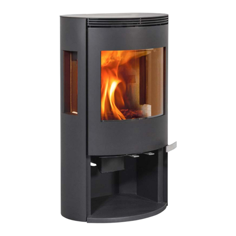
ILD 15 ECO User manual

ENGLISH
ILD 15 ECO
EN 13240 - NS 3058
Manual
Model ILD 15 ECO
VERSION NO. 2, 12.08.2021


3
ENGLISH
Content
Dane techniczne................................................................................................................... 4
Przed instalacją .................................................................................................................... 5
Opakowanie.......................................................................................................................... 5
Pierwsze użycie.................................................................................................................... 5
Montaż.................................................................................................................................. 5
Górne/tylne podłączenie do przewodu dymowego............................................................... 6
Akcesoria.............................................................................................................................. 9
Płyta podłogowa ................................................................................................................... 9
Części eksploatacyjne........................................................................................................ 10
Zamknięty system spalania ................................................................................................ 11
Komin i króciec dymowy..................................................................................................... 11
Dokładanie paliwa i przeładowanie pieca........................................................................... 12
Paliwo................................................................................................................................. 12
Dokładanie paliwa do wygasającego pieca........................................................................ 13
Użycie w sposób przyjazny dla środowiska........................................................................ 13
Używanie pieca w różnych warunkach pogodowych.......................................................... 13
Regulator powietrza do rozpalania..................................................................................... 14
Regulator powietrza do palenia.......................................................................................... 14
Popielnik i ruszt ................................................................................................................. 15
Usuwanie resztek popiołu................................................................................................... 16
Otwarte regulatory dopływu powietrza ............................................................................... 16
Zasady ogólne.................................................................................................................... 16
Rozpalanie pieca metodą „od góry”.................................................................................... 17
Czyszczenie i konserwacja................................................................................................. 18
Wymiary.............................................................................................................................. 19
Odległość od materiałów palnych, z izolowaną rurą dymową ............................................ 20
Odległość od ściany ogniowej, z izolowaną rurą dymową.................................................. 20
Bezpieczna odległość......................................................................................................... 20
Rozwiązywanie problemów ................................................................................................ 21

4
ENGLISH
Test in compliance with EN 13240
Model 15 ECO
CO Emission at 13% O
2
0,0964 %
CO
Emission at 13% O
2
1205 mg/Nm
3
Dust @ 13% O
2
19 mg/Nm
3
No
x
@ 13% O
2
96 mg/Nm
3
Eciency 77 %
Energy eciency index 102,65
Energy eency classs A
Nominel output 5,5 kW
Chimney temperature EN 13240 281 °C
Amount of smoke 6,0 g/sec
Sub-pressure EN 13240 12 Pa
Recommended sub-pressure in connecting piece 18 Pa
Required combustion air supply 17,6 m
3
/h
Fuel Wood
Fuel consumption 1,90 kg/h
Amount of fuel 1,40 kg
Amount of fuel, max 2,10 kg
Refuelling frequency for nominal output 45 min
Weight 109 kg
Internal flue connection piece, internal diameter 135 mm
External flue connection piece, external diameter 148 mm
Max. fuelsize diameter 10 cm
Max. fuel length 30 cm
Ild is a range of safe, environmentally friendly and ecient high-quality stoves, which meet all
requirements for a modern heating source. In order to get the best out of your stove, we
recommend that you read this booklet carefully.
Technical Data Sheet

5
ENGLISH
Before the Installation
Ensure that your Local registered installer can recommend wood stove installation.
Ensure that updated European, national and local standards can be fulfilled.
Ensure that the area can support the stove and installation weight.
Ensure that there will be sucient space and access to service.
Ensure that the heat output of the stove is suitable for the room.
Warning! Do not make any unauthorized changing on the stove.
Packing
The stove comes on a wooden pallet with a wood frame nailed down on vertical boards at the
corners.
Consult local regulations on the disposal of these materials; the wood has been treated to repel
vermin and may not be burnt in the stove.
First Time Use
Before the stove is heated up for the first time, we advise you to open all the doors and
windows in the room where the stove is installed, to ensure an optimal ventilation. When the
stove has reached operating temperature, the surface treatment will harden and emit a strong
odor for a short time.
Mounting
Before mounting, ensure that the base is even and secure. It has to be able to carry the weight
of the stove as well as the chimney and any other equipment.
There must be a fire resistant floor or floor plate around the stove to protect the floor against
damages from sparks. National and local regulations must always be respected.
If it is necessary to connect an elbow pipe, a curved rather than a sharp elbow pipe is
recommended as this causes the least possible reduction in the chimney draught. See more
under general directions and chimney.

6
ENGLISH
Flue Connection Pipe / Rear Outlet
1. Pull the heat shield of the inner mantle up
and take it out.
2. Loosen the cover plate by turning it back
and forth until it loosens.
3. Drill a hole (Ø 8 mm) in all fasten points
of the cover plate for rear outlet in the
outer mantle.
4. Remove the cover plate.

7
ENGLISH
5. Lift out the bae plates by removing the
pins holding the plates. First remove the
lower plate, then the upper.
6. Remove the bolts from the cover plate.
7. Beat carefully with a hammer on the
inside until the plate loosens.
8. Then move the plate to the top outlet.

8
ENGLISH
9. Mount the bolts on the cover plate.
10. Finally you can mount the flue connecting
piece in the rear outlet
Remember to remount the heat shield
in the inner mantle!

9
ENGLISH
Accessories
Shaped floor plate - glass: 642x471 mm: 50061419
Floor plate
If you are placing the stove on a flammable floor, you must comply with the national and local
regulations on the size of any non-flammable subsurface required to cover the floor around the
stove.
Your local dealer can advise you on regulations concerning protection of flammable materials in
the vicinity of your stove.
The floor plate’s function is to protect the floor and flammable material against any sparks that
may occur. A floor plate can be made of steel or glass, but the stove can also be erected on clinker
concrete, natural stone or similar materials.
The stove has adjustment screws under the stove. Use the adjustment screws to get the stove
to stand straight and level. If the floor plate is used, the stove must be adjusted so that the
plate can be placed under the front of the stove.
NOTICE: It is very important that the stove is level to allow an optimal function of the
door. Please note that once mounted the stove can no longer be adjusted!

10
ENGLISH
Bae plates
Wearing Parts
When replacing or cleaning the combustion chamber´s insulation (vermiculite), first remove the
bae plate.
Gently lift the plate and remove the pins in the side plates holding the plate in place. Push the
front of the deflector plate upwards and turn it carefully making it possible to remove the plate
from the burn chamber.
Then remove the top deflector plate. The side plates and finally the back plate can now be
removed. Do this gently in order not to damage the plates.

11
ENGLISH
Closed Combustion System
In well-insulated houses, the air used up by the burning process has to be replaced. For this
purpose you can mount the delivered fresh air connection piece (Ø 100 mm) at the bottom or at
the rear of the stove and connect it to the outside.
The installation must have a maximum length of 6 m and a consist of maximum 3 bends as well
as a single inlet grate. The total counter pressure must not exceed 2 Pa., at a minimum chimney
draught of 18 Pa, measured at the stoves connecting piece.
Special weather and geographical conditions mean that the installation must always be carried
out and approved by a ventilation specialist.
We recommend the mounting of a valve, so that it is possible to close for the ventilation system.
If the stove is not in use for a longer period, this valve can be closed to prevent draft.
Chimney & Flue Connecting Piece
The chimney must have a minimum draught of 18 Pa. measured at the stove´s connecting piece.
If you are not sure of the stove´s draught, a chimney sweep can measure it.
The chimney sweep will also ensure that the chimney is airtight, safe and equipped with a
cleanout door. If there are any other connections to the chimney, the chimney sweep should also
be asked for advice before installation.
Upon delivery, the flue pipe connecting piece is located inside the stove, for transport. The
connecting piece can be connected directly to the stove´s top outlet.
If a rear connection is required, move the cover plate to the top outlet and the connection piece
from the top to the rear outlet. You will find more about this under installation.
The local building and housing authorities must always approve the installation.
The connecting pipe must be CE marked. The requirements to the chimney and the flue pipe in
terms of safety distances must be met.
Remember always to ensure that the gasket between the stove and flue connecting piece is
intact and airtight.
Do not place more than 30 kg on top of the stove/connecting piece. This can damage the stove.
It is important that stove, flue pipe and chimney are situated with enough space for cleaning
sweeping and emptying.

12
ENGLISH
Type of wood Dry wood Kg/m³ Compared to beech %
Hornbeam 640 110
Beech 580 100
Ash 570 98
Oak 570 98
Maple 570 98
Birch 540 88
Mountain pine 490 83
Spruce 370 65
Poplar 370 65
Stoking and Overloading
The stove is approved as an intermitted heater which means that you must stoke the stove with
a suitable amount of fuel (see data) which then burns down into embers before you stoke it the
next time.
The maximum amount of fuel specified in this manual should not be exceeded, overloading can
cause excess smoke.
Any part of the fuel must not be placed at a higher level than the lower part of the metal piece
in the backside of the burn chamber. Be careful not to overload the stove as this causes wear
and tear to the stove and may, in serious cases, destroy the stove. The maximum amount of fuel
specified, (see data) should not be exceeded, as overloading can cause excessive smoke. The
recommended frequency for firing is 45 min.
Fuel
Any dry and seasoned woods can be used. There are however major dierences in density,
tendency to spark, processing, time of seasoning and burning time.
Don’t ever use wood treated with any chemicals
Don’t ever use any liquid fuels
Don’t ever use any kind of waste materials in the stove
Use wood fuel only!
It is recommended to buy a moisture content meter. Make it a habit to check that your wood has
less than 18% moisture content, preferably 16 %.

13
ENGLISH
Refueling on to a Low Fire Bed
If there is insucient burning material in the fire bed to ignite a new fuel charge, excessive
smoke emission can occur. Refueling must be carried out onto a sucient quantity of glowing
embers and ashes that the new fuel charge will ignite within a reasonable period. If there are
too few embers in the fire bed, add suitable kindling to prevent excessive smoke.
As a result of the heating and due to the ensuing change in temperature, the stove may produce
sounds which can be loud and variated.
Environmental Use
It is important to us that our environment is protected in best possible way – first of all, it is an
advantage to all, and as a bonus the fuel is exploited much better.
The air supply for the combustion is added through 2 valves controlled by 2 control handles.
The left control handle is the primary air, which is used for lighting the cold stove and when
firing dense wood. Maximum air is added, when the control is in the furthest left position; when
fire is established, gently close the primary control by sliding it towards the right.
The right air control (secondary air) is to be used when the stove is warm to control the fire. It
is open when pushed to the right, and restricted when pushed to the left. The fire should be run
eciently, and the best indication of this is the color of the firebricks inside the firebox. If they
are soothed up, then the fire is burning too cold, and this should be corrected.
Please also notice that the logs must be max. 30 cm long and no more than 10 cm in diameter;
the moisture percentage must be lower than 18%.
Using Your Stove under Various Weather Conditions
Wind blowing on the chimney can have a great eect on how your stove reacts; you may need
to adjust the airflow to achieve good burning results. Fitting a damper in the flue pipe may also
help, as it will give you the ability to regulate the draught in changing wind conditions.
Fog can also have a great influence on how well a chimney draws; you may again need to adjust
the airflow settings to achieve good burning results.

14
ENGLISH
Primary Air Control
During normal heating, the primary air control is typically open between 0 and 50 %.
0% may be used for burning soft wood and 50 % for hard wood. In unusual weather conditions
causing poor draught, it may be necessary to start up the stove with full primary air open. As
the stove heats up slowly, decrease the primary lever towards the right. See also passage for
lighting the stove.
Far left: fully open primary air. Far right: closed primary air
Secondary Air Control
During normal heating, the secondary air control is typically open between 40 and 70 %. The
secondary air control determines the performance of the stove. This stove is delivered with a
lock preventing the secondary air from closing completely.
In addition to participating in the combustion, the secondary air will also prevent formation of
soot on the glass.
Far left: closed secondary air. Far right: open secondary air

15
ENGLISH
Ash Drawer and Bottom Grate
Ash residues can occur from time to time, and it is recommended that the ash drawer area is
periodically inspected and cleaned out using a suitable vacuum cleaner.
Make it a routine to check that the door gasket is firm and intact each time stove is cleaned.
Tip
The door is provided with a spring that can pull the door to closed position, without closing the
door. The handle still needs to be activated to close the door.
Ash drawer

ENGLISH
Cutting Out Ash Residues
At the front of the burn chamber there is a channel, which is designed to collect loose ashes
when the stove is being used.
When cleaning the stove, use a suitable vacuum cleaner.
IMPORTANT!! Make sure that all ashes are cold, as there may still be embers present a long time
after the fire has burned out.
Dampers Left Open
Operation with the air controls open can cause excess smoke. The appliance must not be
operated with air controls or door left open except as directed in the instructions.
General Rules
There should always be at least 50 mm distance between the product and a fire wall, see
Installation examples.
Report the installation to local building authorities and the chimney sweep.

ENGLISH
17
Lighting the Stove Using a “Top-Down”-Lighting
“Top-Down”-Lighting provides an environmentally friendly lighting and helps keep the glass area
optimally clean.
• 4 pieces of wood approx. 20-25 cm long with a weight of approx. 0.5-0.6 kg per piece.
• 6-10 thin pieces of firewood of about 20-25 cm in length, with a total weight of approx.
0.6-0.8 kg.
• 3 fire lighters in bag or block form
Place the pieces of wood, firewood and fire lighters in the combustion chamber as shown below.
Set the primary and secondary air controls to maximum in the lighting phase. If the fire is too
strong, you may throttle down the primary air damper.
NOTE: The wood must never be placed higher than the tertiary holes at the rear of the
burn chamber (this does not apply at a cold start)!
Warning! All exposed surfaces of this stove will reach high temperatures. Remember always to
use the glove provided during the operation.
After the lighting procedure, please see passage regarding primary and secondary air control for
intermittent use. Do not use the stove with the door open. Unless you are refueling the fire, the
door should be closed.
It is recommended to stoke no less than 2 pieces of wood at each refueling.
At the EN 13240-test the stove was fired as shown on
the picture:
With three pieces of birch each 180 mm
– with a total weight of 1.4 kg.
Primary air damper 50 % open
Secondary air damper 60 % open

18
ENGLISH
Cleaning and Maintenance
The stove can be wiped with a dry and lint-free cloth. The ceramic glass can also be wiped with
a dry cloth, or you can buy a special glass cleaner at your authorized dealer’s. The glass cleaner
must be used as directed. Never use cleaning agents with abrasive properties.
The combustion chamber lining is a wearing part that must be protected against knocks and
shocks. The lining may be used in spite of small cracks, but if it begins to crumble, it must be
replaced.
Prior to any required sweeping, the smoke deflector plate must be removed by gently lifting the
plates and removing the pins.
With daily use, make sure that the seals are intact and ensure that they are replaced before they
allow leakage.
Always remember to ventilate the room after repairs to painted surfaces and the use of care
products.
Once a year, or more, according to national and local rules, stove should be cleaned properly, in
order to make sure that dust and ashes are cleaned out from the convection area. This service
which must be undertaken by a qualified specialist, should include sweeping, leak test and
service of the flue liner. If the stove has been out of use for longer periods, always perform this
service.
Please also see passage: Ash drawer and bottom grate for regular service routine.
Don’t ever use any spare parts not recommended by an authorised dealer.

1088,49
382
507,80
A3
WARM 15
Naziv:
Masa: 96.19 kg
27.3.2019.
Material <not specified>
List:1/1
Mjerilo: 1:7
27.3.2019.
27.3.2019.
hrapavost
2768
27682768
2768
258-00-000
DIN ISO
DIN ISODIN ISO
DIN ISO
Područje primjene: Dopušteno
1302
13021302
1302
St.iz. Izmjena Datum Ime Izvor: Zamjena za: Zamjenjen sa:
Izradio
Provjerio
Norma
Odobrio
Datum Ime
Mario Horvat
Model ili kalup-broj:
Broj crteža:
odstupanje
DIN ISO
DIN ISODIN ISO
DIN ISO
258-00-000 WARM 15
Površinska
Materijal, poluproizvod:
Sirovac broj:
27.3.2019.
100
454
307
150
936
19
ENGLISH
Measurements

NAVN:
STI:
DIMENSION:
MATERIALE: DATO: SIGN:
Krog Iversen & Co A/S
DK-5492 Vissenbjerg©
TG.NR:EMNE:
C:\Working Folder\Designs\Scan 59 ECO\90559002.idw
90559002
Opstillingstegninger - brandbar væg (baseret påScan
59)
07-05-2020 KEN
Scan 59 ECO
VÆGT:
AREAL:
N/A
N/A
450
100
*
150*
150
*
NAVN:
STI:
DIMENSION:
MATERIALE: DATO: SIGN:
Krog Iversen & Co A/S
DK-5492 Vissenbjerg©
TG.NR:EMNE:
C:\Working Folder\Designs\Scan 59 ECO\90559002.idw
90559002
Opstillingstegninger - brandbar væg (baseret påScan
59)
07-05-2020 KEN
Scan 59 ECO
VÆGT:
AREAL:
N/A
N/A
450
100
*
150*
150
*
NAVN:
STI:
DIMENSION:
MATERIALE: DATO: SIGN:
Krog Iversen & Co A/S
DK-5492 Vissenbjerg©
TG.NR:EMNE:
C:\Working Folder\Designs\Scan 59 ECO\90559001.idw
90559001
Opstillingstegninger - brandmur (baseret påScan 59)
07-05-2020 KEN
Scan 59 ECO
VÆGT:
AREAL:
N/A
N/A
50
*
50
*
100
*
200* 100*
800* *1000
*1000
800*
800
*
20
ENGLISH
Distance to Flammable Materials, with Insulated Flue Pipe
*Insulated length
Safety Distance
European, national and local regulations concerning safety distances for wood-burning stoves
must be complied with.
Distance to Firewall, with Insulated Flue Pipe
Distance to furniture: 1000 mm.
You should however assess whether furniture or other items might become excessively dry
due to being too close to the stove.
Table of contents
Other ILD Stove manuals
Popular Stove manuals by other brands

FRANCO BELGE
FRANCO BELGE Belfort Installation
HUUM
HUUM HIVE HEAT 12 Installation and user instructions

Vogelzang International
Vogelzang International VG5713 Owner’s Instruction and Operation Manual
Hi-Flame
Hi-Flame Horse Flame HF905-SE Precision I instruction manual
Tiger
Tiger 944 Installer's guide
WANDERS
WANDERS NORMANDIE Instructions For Use & Installation Manual

HASE
HASE Asmara Instructions for use
Dovre
Dovre 425 Instructions for use installation and servicing

Harrie Leenders
Harrie Leenders PHAROS INTERIOR Installation instruction

Optimus
Optimus HIKER+ Camp stoves
MCZ
MCZ MUSA Hydromatic 16 M1 installation guide

Kingsman Fireplaces
Kingsman Fireplaces FDV451N installation instructions
