ILITCH ELECTRONICS CVNCS-JR User manual

Cavity Noise Canceling System-JR (CVNCS-JR)
User's manual and installation instructions
This product is mainly designed for retrofit on a guitar, having one or more single coil magnetic pickups.
The CVNCS-JR is adapted to replace the control cavity cover located on the ack of LP Junior style guitar ody.
The CVNCS-JR contains a low impedance coil assem ly so it effectively eliminates the noise while the single coil
pickup tone retains unaltered. The CVNCS-JR is an easy to install passive system.
The est way to install the CVNCS-JR is to use professional service of a guitar uilder or guitar repair shop ut it
can e also installed y anyone that is familiar with guitar electronics, guitar assem ling and wire soldering.
Drilling holes, scratching insulation or heavy ending of the CVNCS-JR could adly damage the unit and cause you
to lose all terms of the warranty.
Tools and materials needed for installation:
Soldering gun, screw driver, wire cutters, soldering wire, shrink tu ing. Optional: a digital multimeter, a piece of foam,
small plastic ag, electrical/masking tape.
Basic requirements:
1. All single coil pickups need to e same kind (i. e. P90 with screw pole pieces) and within the selected est matching DC
resistance range
2. All pickups need to e wound in the same direction and the same magnetic polarity.
3. If there is a RWRP pickup this pickup needs to e replaced with a regular one, or you can modify it to ecome same
polarity as the regular one
4. The pickups switching does not include any "in series" or "out of phase" com ination.
Preparing the guitar for CVNCS-JR installation:
1. If you need to modify the single coil pickups - pull off all strings from tuners and modify the pickups accurately.
2. On the guitar ack - unscrew and remove the plastic control cavity cover.
3. Take a picture or do a simple sketch to memorize the original wiring of your guitar electronics and the pickup wires
connections for any future references.
4. If the pickup output wire is raided type you will need to do ONE of the following ("a" is RECOMENDED):
a) Convert the pickup output wire from two to three conductor wire and use the three conductor wiring diagram
as it is shown on this print ack side (using the added third line for connecting to the system)
) Isolate the output wire using shrink tu ing or isolation type so the pickup raided shield will not e connected
to GROUND. You will need to unsolder the shield from the Volume pot housing and connect it to the system.
5. Carefully inspect the side cavity edges and cavity walls for wood chips or sticking sharp materials and smooth them if
necessary.
6. Take the Adjusting PCB and make sure that you will e a le to fit it inside of the control cavity easily.
CVNCS-JR installation steps:
A. Prepare your pickup and follow the wiring diagram you have selected to wire the system. Fresh tin with soldering gun
and fresh solder wire every wires you need to solder
B. Solder the ca les coming out of the Adjusting PCB as follows: Green wire to GROUND; Blue wire to Bg. Then insolate
the created soldering joints.
C. Connect the red and yellow wires from the CVNCS-JR coil to the red and yellow wires from the adjusting PCB and
isolate the created joints.
Keep the adjusting PCB outside of the control cavity until you finish the noise canceling adjustments.
Shape the harness and place the CVNCS-JR on the guitar ack holding it y hand, type or loose screws. The CVNCS-JR
yellow and red wires must e pointed toward the control cavity (this is the way it will stay when permanently mounted)
D. Use the additional small plastic supporting cover for the final CVNCS-JR installation (to avoid the CVNCS-JR ending).
Ad usting the CVNCS-JR for best noise cancellation:
1. Put ON some of the guitar strings (at least one), and turn the guitar volume and tone controls to their “MAX”.
2. Connect the guitar to a guitar amplifier using a guitar ca le.
3. Use a correct size screwdriver to adjust the lue trim pots located on the adjusting PCB.
4. Turn the trim pot on the adjusting PCB to their “MAX” (100%). In this way you will e a le to hear some asic hum
noise.
5. Turn “ON” the guitar amplifier and set it up with a gain and loudness, so you can hear some noticea le hum noise.
Play over the strings to check that the pickup operates normally
6. Hold the guitar as you would play on it and get a position near the amplifier ut not less than 3 feet (1 meter). Best
noise canceling result will e achieved with the amplifier located ehind your ack and the guitar approximately parallel to
the amplifier's front face.
7. Turn down (CCW) VR1 trim pot to reduce the noise level. If the noise increases instead of decreasing, unplug the guitar
from the amplifier remove the CVNCS-JR again and swap the wires connection as follows: yellow wire from the adjusting
PCB to the red wire from the CVNCS-JR; red wire from the adjusting PCB to the yellow wire from the CVNCS-JR. Now you
turn down VR1 trim pot until get an optimum noise cancellation.
8. Set the guitar up with all strings, plug it in and dou le check for its normal operation.
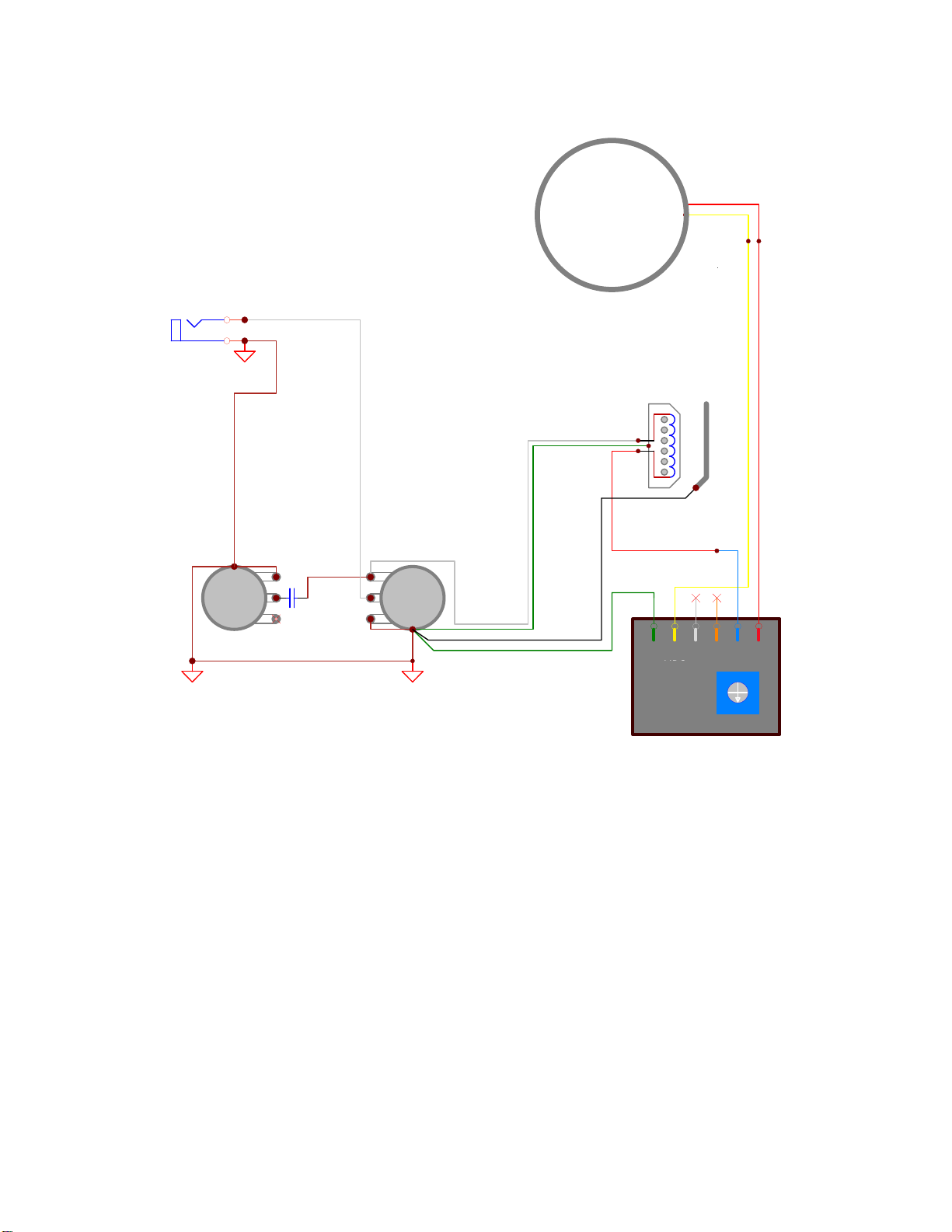
Basic Wiring diagram:
(find more wiring diagrams on the we site - www.ilitchelectronics.com/wirings/)
VR1 - adjust noise canseling for Bridge
VR2 - omited
VR1VR2
Adjusting PCB
Shield
Blue
Red
Yellow
Bg
Main Guitar GROUND
1
2
3
TONE
0.022uF
CVNCS-JR
Output JACK
1
2
3
VOLUME Green
Guitar GROUND
Hot - signal output
RedYellow
G1
C
A
Bridge
B
© ALL RIGHTS RESERVED ILITCH ELECTRONICS LLC
Guitar bridge/strings GND
Signal
Added wire extension
Terms of Limited Warranty. RETURN & EXCHANGE POLICY:
We offer to the original purchaser (For DIRECT SALES from ILITCH ELECTRONICS ONLY) the following terms of Limited
Warranty and RETURN & EXCHANGE POLICY:
1. One year of warranty for all moving parts (i.e. trim potentiometers) of the product.
2. Two years warranty for all non-moving parts (i. e. - capacitors, resistors etc.) of the product. Ilitch Electronics reserves
the right, ased on visual o serving and electrical measuring, to determine what has caused a defect. Damages caused y
accident, a use, alteration, or misuse are not covered y this warranty. Product appearance and normal "wear and tear"
(worn paint, scratches, etc.) are not covered y this warranty.
3. We offer a four weeks money ack policy for customers not satisfied with the purchase. You have to contact us first to
get a return authorization num er (RAN).
A refund will exclude all shipping and handling costs PayPal fees and an additional 15% restocking fee will e applied. The
product needs to e in its original condition and packaging that you have received it from us.
Customer’s Name:…………………………………………… Date of purchase :…………………………
All rights reserved without notification.
ILITCH ELECTRONICS LLC
Camarillo, CA, 93010
Phone: 805 284 2775;
www.ilitchelectronics.com
Table of contents
Other ILITCH ELECTRONICS Accessories For Musical Instruments manuals


Popular Accessories For Musical Instruments manuals by other brands


DAMPP-CHASER
DAMPP-CHASER Piano Life Saver System installation instructions

Harman
Harman dbx dB12 owner's manual

HyVibe
HyVibe Lag HyVibe System 1 user manual

Harley Benton
Harley Benton TrueTone SH-30 Pro Active quick start guide

Sonodyne
Sonodyne BMS 205 owner's manual

Wenger
Wenger Gearboss Center Soft Divider Series owner's manual


