Illumra E3X-T02-U2W User manual

1
Copyright © 2009 ILLUMRA. All rights reserved. Contact ILLUMRA: 777 S. State St., Orem, UT 84058 | T: (801) 349-1200 | F: (801) 653-4257 | [email protected] | [email protected] | www.ILLUMRA.com
Installation Guide
E3X-T02-U2W 24VAC Thermostat
Overview
e 24VAC ermostat provides digital temperature control of heating and cooling–with
wireless communication to multiple ILLUMRA devices. It is designed for use on PTHP/
PTAC Systems, 4-pipe or 2-pipe fan coil systems, and most basic gas/electric furnace/air
conditioning units. Solid-state control outputs allow switching of electronic and relay
loads of 1.5 amps. is control operates from a single setpoint with automatic changeover
between heating and cooling. e fan cycles on/off with calls for heating or cooling or can
operate continuously in either low, medium, or high speed. e control can be placed in
economy mode or off mode with 40° freeze protection. Economy mode is enabled and
disabled by one or more compatible transmitters.
Compatible Devices
Key Card Access Switch; E3T-C1AWH
Single Rocker Self-powered Wireless Light Switches; E3T-S1Axx
Dual Rocker Self-powered Wireless Light Switches; E3T-S2Axx
Dual Rocker Handheld Remote; E3T-S2Hxx
SLT Wireless Sensor; E3T-Rxx-2INBP
Self-powered Wireless Occupancy Sensor; E3T-Mxx-SB24
More transmitters available
Components Included
e following items are included with this product:
A -- (1) ILLUMRA 24VAC ermostat
B -- (2) Mounting Screws (6/32” x 3/4”)
C -- (1) Selft Tapping Screw
D -- (1) Mounting Bracket
Optional Accessories
A -- Horizontal Converse Mounting Plate (not included)
Tools Needed for Installation
Phillips Screwdriver
Electrical Tape
Wire Nuts
■
■
■
■
■
■
■
■
■
■
■
■
■
■
■
Programming the Thermostat
CAUTION: ILLUMRA Relay Receivers are to be installed and/or used in compliance
with relevant electrical codes and regulations. If you are unsure about any portion of
these instructions, please contact a qualified electrician. ese devices are intended for
indoor use, for permanently installed fixtures, and for dry locations.
Connect the thermostat to a 24VAC power source for initial setup. DO NOT
CONNECT THE OTHER WIRES UNTIL THIS STEP IS COMPLETE. PREVENT
ALL OTHER WIRES FROM TOUCHING DURING THIS PROCESS TO
AVOID DAMAGE TO THE THERMOSTAT. DAMAGE DUE TO INCORRECT
WIRING WILL VOID WARRANTY. e programming mode has a time limit of 10
minutes. After 10 minutes, the thermostat will resume normal operation. e default
values mentioned throughout this section refer to factory programmed settings. If the
thermostat has been custom programmed, the defaults may not apply.
Access Code 43:
Conguration Mode
Step 1: Place thermostat into programming mode by pressing and holding the UP
and DOWN arrows while sliding the °F/°C switch to the opposite side. 00
will appear on the display. Do not use the °F/°C switch again until done
programming.
Step 2: Press either the up or down arrow button to find the access code 43 then
press the fan button.
Step 3: Press either the up or down arrow button to scroll through the menu to
reach the desired parameter (see below), then press the Fan button.
Equipment Type (E9P): Type of Equipment
tHP - Default, Trane heat pump, type O reverse valve
tAC - Trane AC with electric heat
FHP - Friedrich heat pump, type B reverse valve
FAC - Friedrich AC with electric heat
gHP - GE heat pump, type B reverse valve
gAC - GE AC with electric heat
AHP - Amana heat pump, type B reverse valve
AAC - Amana AC with electric heat
FC - fan coil
Reverse Valve Type (typ): Selects the valve type
O type - Default, energizes in calls for cooling
B type - energizes in calls for heating
Heat Pump or AC (Pt):
HP - Default, 2 stage heat, single stage cool
Y = compressor, W = 2nd stage heat
AC - AC and electric heat
Y = cool, W = heat
Fan Speed and Operation (FOp):
1U - single speed user selectable fan
1C - single speed constant fan
1A - single speed auto fan
2U - Default, two speed user selectable fan
2C - two speed constant fan
2A - two speed auto fan
ree speed fan only available for fan coil equipment
3U - three speed user selectable fan
3C - three speed constant fan
3A - three speed auto fan
Compressor Protection (FCp): Selects the compressor protection and high or low
speed fan in heating
CP - Default heat pump, compressor protection and high fan is allowed in heating
NP - Default fan coil, no compressor protection and high fan is allowed in heating
CP - compressor protection and high fan is allowed in heating
nP - no compressor protection and only low fan is allowed in heating
cP - compressor protection and only low fan is allowed in heating
Continuous Fan Operation (CFL): Selects continuous fan operation
Dis - Default, normal fan operation
Ena - continuous low fan in auto or economy modes
Step 4: Press either up or down to reach desired change.
Step 5: Press fan button to return to program menu.
Step 6: Press Up or Down arrow until End / Prog appear on the display.
Step 7: Press fan button to save changes and exit the program mode. You will need
to re-enter programming mode to access a different code.
Access Code 79:
Field Programming Mode
Step 1: Place thermostat into programming mode by pressing and holding the UP
and DOWN arrows while sliding the °F/°C switch to the opposite side. 00
will appear on the display. Do not use the °F/°C switch again until done
programming.
Step 2: Press either the up or down arrow button to find the access code 79 then
press the fan button.
Step 3: Press either the up or down arrow button to scroll through the menu to
reach the desired parameter (see below), then press the Fan button.
Step 4: Press either up or down to reach desired change.
Temperature Scale (Unt): Selects scale parameter that will be shown
F - Default,°F
C - °C
Display Temperature (dSP): Selects which temperature is shown on display
SP - Default, display will show setpoint only
rt - display will show room temperatue unless either up or down arrow button is
pressed. en the display will show setpoint.
Srt - display will toggle between room temperature and setpoint. Display will
revert to setpoint when either the up or down arrow button is pressed.
Temperature Control Mode (HAc):
USr - Default, switch selectable, heat only, auto changeover or cool only
AUt - auto mode only
CL - cool mode only
Ht - heat mode only
Off Function Enabled (OFf ): Selects whether or not thermostat can be turned off by
pressing the fan button
Ena – Default, enabled, press fan button until OFF appears on display
dis – disabled
Economy Function Enabled (ECo): Selects whether or not thermostat can be
manually placed in economy mode by pressing the fan
button

2
Copyright © 2009 ILLUMRA. All rights reserved. Contact ILLUMRA: 777 S. State St., Orem, UT 84058 | T: (801) 349-1200 | F: (801) 653-4257 | [email protected] | [email protected] | www.ILLUMRA.com
Ena – Default, enabled, press fan button until Eco and
ECON appears on display
dis – disabled
Comfort Setpoint (CS): Selects setpoint default temperature when thermostat
powers up or returns to comfort mode from economy mode
72.0°F (22.0°C) Default
Programmable Range: 60.0°F to 85.0°F (15.5°C to 29.5°C)
Cooling Limit (LC): Selects minimum room temperature in cooling
65.0°F (18.5°C) Default
Programmable Range: 60.0°F to 85.0°F (15.5°C to 29.5°C)
Heating Limit (LH): Selects maximum room temperature in heating
85.0°F (29.5°C) Default
Programmable Range: 60.0°F to 85.0°F (15.5°C to 29.5°C)
Freeze Protection (FP): Selects freeze protection enabled or disabled
Ena – Default, enabled at 40°F
dis – disabled
Fan Purge Timer (FPt): Selects the amount of time the fan will continue to run
after a heating or cooling call.
30 seconds Default
Programmable Range: 0 (Off) to 180 seconds (3 minutes), in 10 second
increment
Clear Logged Data (CLr): Selects whether or not the logged run time data will be
reset to 0’s
no – Default, no reset
Yes – reset
Setback Ramping (Sbr): Selects setback function to step back to economy
setpoints or to go directly to economy setpoints.
dis - Default, disabled, directly to economy setpoint
Ena – enabled, ramps to economy setpoints
OFf - directly to Off mode
Ramping Setback Timer (rSt): After setback is initiated, selects the amount
of time the setpoint will be stepped back by the degrees per setback
Example: if both parameters are defaulted, the thermostat will step back
1° per every 30 minutes until either the economy cooling limit (EC) or
the economy heating limit (EC) is reached.
30 minutes Default
Programmable Range: 1 minute to 720 minutes (12 hours), in 15 minute
increment
Degrees Per Setback (dPs): Selects the number of degrees per time period that the
setpoint will be stepped back
1° Default
Programmable Range: 0°F to 3°F, in 0.5°F increments
Economy Cooling Limit (EC): When in economy or remote setback mode, selects
the highest room temperature before cooling turns on. Cooling turns off
when temperature falls below EC value.
85.0°F (29.5°C) Default
Programmable Range: 72.0°F to 99.0°F (22.0°C to 37.0°C), in 0.5°F increments
Economy Heating Limit (EH): When in economy or remote setback mode, selects
the lowest room temperature before heating turns on. Heating turns off
when temperature rises above EH value.
60.0°F (15.5°C) Default
Programmable Range: 41.0°F to 72.0°F (5.0°C to 22.0°C), in 0.5°F
increments
Fan Refresh Frequency (FrF): Selects how often the low fan will operate for a fan refresh 0
hours Default, disabled
Programmable Range: 0 hours to 24 hours
Fan Refresh Duration (Frd): Selects the length of time the low fan will operate during a
fan refresh
1 minute Default
Programmable Range: 1 minute to 45 minutes
Cycle Rate Timer (crt): Limits the number of heat/cool cycles per hour
6 cycles per hour Default, heat pump
8 cycles per hour Default, fan coil
Programmable Range: 0 (Off) to 12 cycles per hour, heat pump
Programmable Range: 0 (Off) to 24 cycles per hour, fan coil
Differential (Dif): Selects the minimum room temperature above or below setpoint when
heating or cooling will turn on or off.
0.4°F (0.2°C) Default
Programmable Range (°F): 0.2, 0.4, 0.6, 0.8, 1.0, 1.2
Programmable Range (°C): 0.1, 0.2, 0.3, 0.4, 0.5, 0.6
Setpoint Hold Timer (SH): Selects a time limit that the occupant’s setpoint will be saved,
when in economy mode.
0 hours Default, disabled
Programmable Range: 0 to 24 hours
Fan Hold Timer (HFt): Selects a time limit the high and low fans will operate before
automatically returning to auto mode.
0 hours Default, disabled
Programmable Range: 0 to 24 hours
Shutdown Delay (Sdd): Selects the amount of time delay between remote shutdown
signal and the thermostat going into shutdown mode.
0 seconds Default, immediate
Programmable Range: 0 seconds to 200 minutes
Step 5: Press fan button to return to program menu.
Step 6: Press Up or Down arrow until End / Prog appear on the display.
Step 7: Press fan button to save changes and exit the program mode. You will need to
re-enter programming mode to access a different code.
Access Code 92:
Restore Factory Presets
Step 1: Place thermostat into programming mode by pressing and holding the UP
and DOWN arrows while sliding the °F/°C switch to the opposite side. 00
will appear on the display. Do not use the °F/°C switch again until done
programming.
Step 2: Press either the up or down arrow button to find the access code 92 then press
the fan button.
Step 3: All and Erase will appear on the display. Press the fan button again to rest to
factory defaults.
Step 4: Press Up or Down arrow until End / Prog appear on the display.
Step 5: Press fan button to save changes and exit the program mode. You will need to
re-enter programming mode to access a different code.
NOTE: is procedure does not affect the stored switches in memory. See the
“Programming the Radio Receiver” section for methods to clear this memory.
Installation
Junction box mounting is highly recommended. For optimal radio performance do
not mount or place the receivers close to the floor or inside a metal housing.
INSTALLATION OPTION A:
Heat Pump Conguration
Step 1: Read all steps for this option before taking any action to install
thermostat.
Step 2: WARNING: To avoid risk of fire, shock, or death, TURN OFF POWER
at circuit breaker or fuse and verify that it is OFF before installation
begins. Make sure that it remains OFF until installation is complete.
Step 3: If retrofitting old thermostat, remove old thermostat, carefully noting
the wire connections on the old unit. Record wire color and terminal
legeneds (Cable wire color for Control Feed, Load Feed, Common,
Auxiliary Heat, Compressor, Low Fan, High Fan, and Reversing Valve).
Step 4: Install mounting bracket to the junction box with provided mounting
screws.
Step 5: Wire thermostat according to function as shown in Figure A.
Step 6: Push wires into junction box. Rest bottom of thermostat on mounting
tabs in mounting plate. Push top of thermostat towards wall and secure
into place with self-tapping screw.
Step 7: Turn power on.
INSTALLATION OPTION B:
4-Pipe Fan Coil Conguration
Step 1: Read all steps for this option before taking any action to install
thermostat.
Step 2: WARNING: To avoid risk of fire, shock, or death, TURN OFF POWER
at circuit breaker or fuse and verify that it is OFF before installation
begins. Make sure that it remains OFF until installation is complete.
Step 3: If retrofitting old thermostat, remove old thermostat, carefully noting
the wire connectinos on the old unit. Record wire color and terminal
legeneds (Cable wire color for Control Feed, Load Feed, Common,
Auxiliary Heat, Compressor, Low Fan, High Fan, and Reversing Valve).
Step 4: Install mounting bracket to the junction box with provided mounting
screws.
Step 5: Wire thermostat according to function as shown in Figure B. NOTE: If
the mechanical system has only two fan speeds: Green - Low Fan, Violet
- High Fan, Orange - Not used.
Step 6: Push wires into junction box. Rest bottom of thermostat on mounting
tabs in mounting plate. Push top of thermostat towards wall and secure
into place with self-tapping screw (included).
Step 7: Turn power On.
INSTALLATION OPTION C:
2-Pipe Fan Coil Conguration
NOTE: Continuous fan is not available on 2-Pipe with aquastat systems.
Continuous fan is available on 2-Pipe with electric heat systems.
Step 1: Follow instructions for a 4-Pipe installation but using Figure C for 2-Pipe
Fan Coil with Aquastat or Figure D for 2-Pipe Fan Coil with Electric
Heat.
Step 2: Push wires into junction box. Rest bottom of thermostat on mounting
tabs in mounting plate. Push top of thermostat towards wall and secure
into place with self-tapping screw (included).
Step 3: Turn power On.
3
Copyright © 2009 ILLUMRA. All rights reserved. Contact ILLUMRA: 777 S. State St., Orem, UT 84058 | T: (801) 349-1200 | F: (801) 653-4257 | [email protected] | [email protected] | www.ILLUMRA.com
Programming the Radio Receiver
e thermostat can be configured to operate with many ILLUMRA transmitters. Depending on the transmitter type and the intended
application, the thermostat will need to be programmed to operate in Rocker Mode, Momentary Mode, Toggle Mode, or Scene Mode.
Multiple modes can be used with one thermostat. For transmitter installation instructions, see appropriate installation guide. Select the
desired Learn Mode below to program the thermostat.
CLEAR MODE:
Clearing the Switch Memory
In order the clear the switch memory within the thermostat, use the following steps:
Step 1: Press and hold the UP and DOWN butttons until CLR appears on the display (approximately 10 seconds). is will delete
all associated transmitters from the memory.
LEARN MODE 0:
Rocker Mode - Wireless Switch Control of Thermostat
Rocker Mode is usually used with ILLUMRA Wireless Light Switches. e thermostat goes into occupied mode when the top of the
rocker switch is pressed and unoccupied mode when the bottom of the rocker switch is pressed.
Step 1: Place the thermostat into Learn Mode by pressing and holding the UP and DOWN butttons until LRN appears on the
display. e display will alternate between LRN and 0 indicating that it is in Learn Mode 0 - Rocker Mode.
Step 2: Press one of the rockers on the ILLUMRA Wireless Light Switch. e display on the thermostat will briefly display ADD
indicating that it has added that transmitter.
Step 3: e display will resume alternating between LRN and 0 - add more transmitters as desired for this mode (up to 30).
Step 4: To delete a transmitter from the thermostat, press the wireless light switch again. e display on the thermostat will briefly
display DEL indicating that it has deleted that transmitter.
Step 5: Exit Learn Mode by pressing and holding the UP and DOWN buttons until LOC appears on the display or the display
returns to normal operating mode. is indicates that all learned transmitters have been locked into memory on the
thermostat.
NOTE: ese steps are also used for Manual On/Auto Off - Occupancy Sensor Control.
LEARN MODE 1:
Momentary Mode - Keycard Switch Control of Thermostat
Momentary Mode is used with ILLUMRA Wireless Key Card Switches. e thermostat will be in occupied mode when the key card is
inserted and unoccupied when the key card is removed.
Step 1: Place the thermostat into Learn Mode by pressing and holding the UP and DOWN butttons until LRN appears on the
display. e display will alternate between LRN and 0 indicating that it is in Learn Mode 0.
Step 2: Press and release the UP button. e display will alternate between LRN and 1, indicating that it is in Learn Mode 1
- Momentary Mode.
Step 3: Insert a key card into an ILLUMRA Key Card Access Switch. e display on the thermostat will briefly display ADD
indicating that it has added that transmitter.
Step 4: e display will resume alternating between LRN and 1 - add more transmitters as desired for this mode.
Step 5: To delete a transmitter from the thermostat, remove the key card (if inserted) of a learned switch and insert it again. e
display on the thermostat will briefly display DEL indicating that it has deleted that transmitter from memory.
Step 6: Exit Learn Mode by pressing and holding the UP and DOWN buttons until LOC appears on the display or the display
returns to normal operating mode. is indicates that all learned transmitters have been locked into memory on the
thermostat.
NOTE: ese steps are also used for Auto On/Auto Off - Occupancy Sensor Control.
LEARN MODE 2:
Toggle Mode
Toggle Mode is available for future product releases.
Step 1: Place the thermostat into Learn Mode by pressing and holding the UP and DOWN butttons until LRN appears on the
display. e display will alternate between LRN and 0 indicating that it is in Learn Mode 0.
Step 2: Press and release the UP button. e display will alternate between LRN and 1, indicating that it is in Learn Mode 1
- Momentary Mode.
Step 3: Press and release the UP button. e display will alternate between LRN and 2, indicating that it is in Learn Mode 2
- Toggle Mode.
Step 4: Press the transmit button on the desired transmitter. e display on the thermostat will briefly display ADD indicating
that it has added that transmitter.
Step 5: e display will resume alternating between LRN and 2 - add more transmitters as desired for this mode.
Step 6: To delete a transmitter from the thermostat, press the learned transmit button again. e display on the thermostat will
briefly display DEL indicating that it has deleted that transmitter.
Step 7: Exit Learn Mode by pressing and holding the UP and DOWN buttons until LOC appears on the display or the display
returns to normal operating mode. is indicates that all learned transmitters have been locked into memory on the
thermostat.
LEARN MODE 3:
Scene Mode - For Future Product Releases
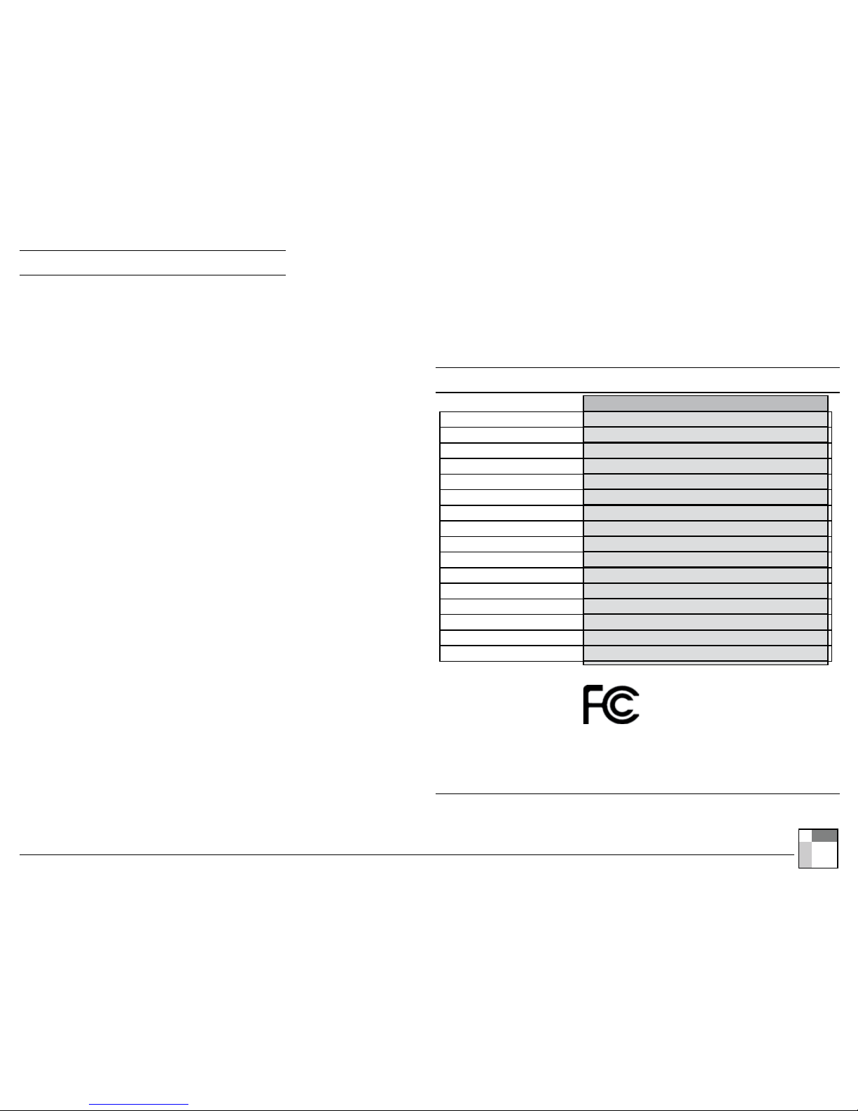
Specications
E3X-T02-U2W
50 to 150 feet
315 MHz
24 VAC
1.5 amp/circuit
32.0°F to 99.9°F (0.0°C to 37.7°C)
60°F to 85°F (15.5°C to 29.5°C)
14°F to 131°F (-10°C to 55°C)
-4°F to 131°F (-20°C to 55°C)
Every 5 seconds
Liquid Crystal Display (LCD)
Selectable: Auto Cycle, Low, Medium, High, Economy, Off
Stores up to 30 switch IDs
+/- 1°F (0.5°C)
1 Heat and 1 Cool circuit
2.11 x 1.73 x 1.09 inches (54 x 44 x 28 mm)
FCC (U.S. SZV-TCM2XXC), IC (Canada 5731A-TCM2XXC)
Range
Frequency
Input Voltage
Max Loads
Temperature Monitor Range
Temperature Set Point Range
Operating Temperature
Storage Temperature
Sampling Rate
Display Format
Fan Control
Memory
Accuracy
Heat/Cool Control
Dimensions
Radio Certications
Complies with Part 15 of the FCC Rules.
Operation is subject to the following two
conditions: (i.) this device may not cause
harmful interference and (ii.) this device must
accept any interference received, including
interference that may cause undesired operation.
Copyright © 2009 ILLUMRA. All rights reserved. Contact ILLUMRA: 777 S. State St., Orem, UT 84058 | T: (801) 349-1200 | F: (801) 653-4257 | [email protected] | [email protected] | www.ILLUMRA.com
4
is device or certain
aspects thereof is protected
by at least one U.S. or
international patent or has
at least one such patent
application pending.
AHD0215A
ILLUMRA is a registered
trademark of Ad Hoc
Electronics. All other
trademarks and names
are the property of their
respective companies.
Warranty
Please refer to www.ILLUMRA.com for updated warranty information
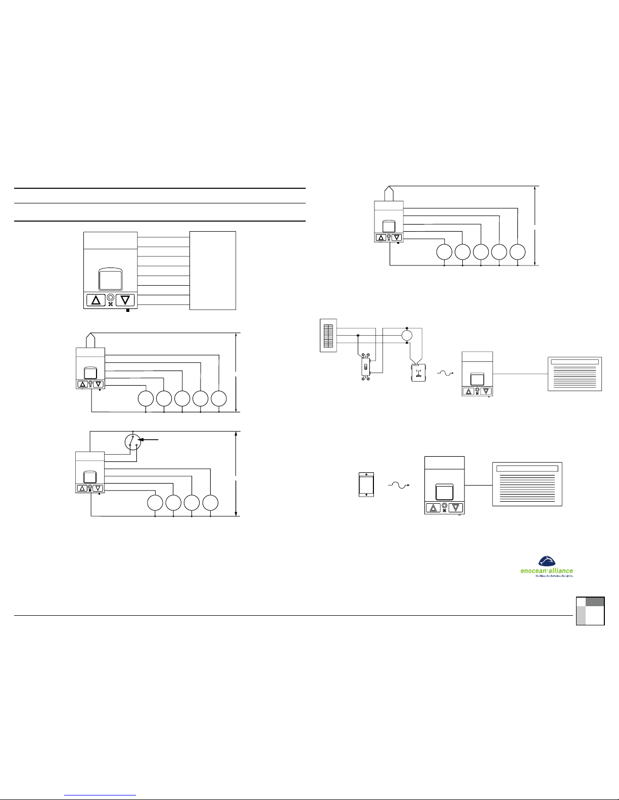
Wiring Diagrams
Figure A: Installation - Heat Pump Conguration
Black
Orange
White
Yellow
Green
Violet
Common
Red/White
Red
Load Feed
Control Feed
Reversing Valve
Auxiliary Heat
Compressor
Low Fan
High Fan
Figure B: Installation - 4-Pipe Fan Coil Conguration
Green
White
Black
Orange
Yellow
Heat
Valve
Feed
Common
24VAC
High
Fan
Relay
Med
Fan
Relay
Low
Fan
Relay
Violet
Cool
Valve
Red Red/White
Figure C: Installation - 2-Pipe Fan Coil with Aquastat Conguration
White
Violet
Aquastat (mounted on water supply line)
or season change switch
Note: Fan will cycle with
heat or cool only
Cool pipe
position
Hot pipe
position
Green
Orange
Red/White
Yellow
Black
Feed
Common
24VAC
High
Fan
Relay
Med
Fan
Relay
Low
Fan
Relay Valve
Red
Figure D: Installation - 2-Pipe Fan Coil with Electric Heat Conguration
Green
White
Black
Orange
Yellow
Electric
Heat
Feed
Common
24VAC
High
Fan
Relay
Med
Fan
Relay
Low
Fan
Relay
Violet
Cool
Valve
Red Red/White
Figure E: Disable HVAC Unit When Existing Light Fixture is Turned Off
ALWAYS INSTALL DEVICES IN ACCORDANCE WITH LOCAL ELECTRICAL REGULATIONS.
WWW.ILLUMRA.COM
DISABLE HVAC UNIT WHEN EXISTING LIGHT FIXTURE IS TURNED OFF
WIRELESS
CONTROL
SIGNAL
HOT
NEUTRAL
WHITE
GREEN OR BARE
GROUND
BLACK
BREAKER PANEL #1
ON/OFF SWITCH
OFF
N.O.
RED
BLACK
COM.
E3T-R12-2INBP
BLACK
WHITE
AC POWER
AC POWER
GREEN OR BARE
AC POWER
WHITE
AC POWER
GROUND
BLACK
LOAD
HVAC UNIT
WHEN THE LIGHT IN THE ROOM IS TURNED ON USING THE EXISTING SWITCH, THE
SLT SENSOR IS TRIGGERED TO TRANSMIT A WIRELESS CONTROL SIGNAL TO THE
ILLUMRA THERMOSTAT, WHICH IN TURN ACTIVATES THE HVAC UNIT. WHEN THE
LIGHTS ARE TURNED OFF, THE HVAC UNIT REVE RTS TO A SET-BACK SETTING.
E3R-120-TSTCP
Figure F: Key Card Switch Control of Thermostat
ALWAYS INSTALL DEVICES IN ACCORDANCE WITH LOCAL ELECTRICAL REGULATIONS.
DISABLE HVAC UNIT WHEN KEY CARD IS REMOVED FROM KEY CARD SWITCH WWW.ILLUMRA.COM
WIRELESS
CONTROL
SIGNAL
E3X-T02-U2W
HVAC UNIT
E3T-C1AWH
KEY CARD SWITCH
Copyright 2009 ILLUMRA www.ILLUMRA.com Sales@ILLUMRA.com Info@ILLUMRA.com T: (801) 349-1200 F: (801) 653-4257
Table of contents
Other Illumra Thermostat manuals


